manuals.online logo
Brands
  1. Home
  2. •
  3. Brands
  4. •
  5. AJAX
  6. •
  7. Accessories
  8. •
  9. AJAX DoorProtect Solar Plus User manual

AJAX DoorProtect Solar Plus User manual

Solar Security
Solar Plus Ajax
DoorProtect
1. FEATURES
Wireless sensor Ajax DoorProtect is designated for doors and windows opening detection.
It functions as a part of Ajax security system.
2. SPECIFICATIONS
SPECIFICATION MEANING
Sensor type wireless
Assembling type removable
Operating level cm (0.4 in) (small magnet), 2 cm (0.8 in)
(big magnet)
Uses indoors
Socket to plug in the wire sensors available
Tamper protection button available
Radio signal power 20 mW
Radio-frequency range 868 MHz (Europe); 9 5 MHz (USA)
Maximum distance between sensor
and central unit 2000 m (6562 ft) (open area)
Power supply CR 23A battery
Power supply voltage 3V
Battery life Up to 7 years
Operation temperatures range from 0°С (+32°F) to +50°С (+ 22°F)
Operation humidity up to 80%
Dimensions Ø20х90 mm (0.78x3.54 in)
3. COMPONENTS
DoorProtect opening detection sensor, magnet, external contact, battery CR 23A,
installation set, manual
4. SETTING-UP PROCEDURES
4. Before installing the sensor, it is required to register it with the Ajax security system. In
order to register the sensor, it is necessary to switch the Ajax security system’s receiver to
«Add Device» mode (the receiver’s manual explains how to accomplish it) and to put the
switch «2» (PICTURE 3) on the sensor to the «ON» position. Sensor’s light must blink at the
moment of switching on. The registration request is transmitted at the moment the sensor
is switched on only! In case the registration was not successful, switch off the sensor, wait
for 5 seconds and switch it on again. If the sensor’s light blinks constantly (each second
during one minute), it means that the sensor is not registered. The light blinks in the same
way if the sensor is deleted from the registration list. Non-registered sensor blinks also
throughout 3 seconds during each activation.
4.2 Having registered the sensor successfully, select an appropriate location to install it.
Solar Security
ATTENTION!
Make sure ha in he ins alla ion loca ion sensor has a s able radio con ac wi h he
receiver! A maximum dis ance of 2000 m (6562 f ) be ween he sensor and he
cen ral uni is men ioned as a comparison wi h o her devices. This dis ance was
found as a resul of open area es s. Connec ion quali y and dis ance be ween he
sensor and he receiver can vary depending on ins alla ion loca ion, walls,
compar men s, bridgings, as well as he hickness and cons ruc ional ma erial.
Signal coming hrough obs acles, loses power. For example, dis ance range be ween
he sensor and receiver, divided wi h wo reinforced concre e bearing walls,
cons i u es approxima ely 30 m (98.4 f ). Please no e ha moving he sensor
alongside he doors even 10 cm (4 in), i is possible o improve he signal recep ion
considerably.
Make sure to check the signal strength! It is possible to launch a signal level test on the
receiver’s side. Test launching is described in the receiver’s manual.
ATTENTION!
Signal level es and de ec ion zone es for sensors ake some ime o s ar . A cer ain
period of ime is necessary for he receiver o send a es reques o he sensor, and for
he sensor o send a es response.
RECEIVER SENSOR'S LIGHT EMITTING DIODE DESCRIPTION
3 indication bars lights almost permanently, with short
breaks each .5 seconds excellent signal
2 indication bars blinks 5 times per second medium signal
indication bar blinks twice per second low signal
0 bars short fl ashes each .5 seconds no signal
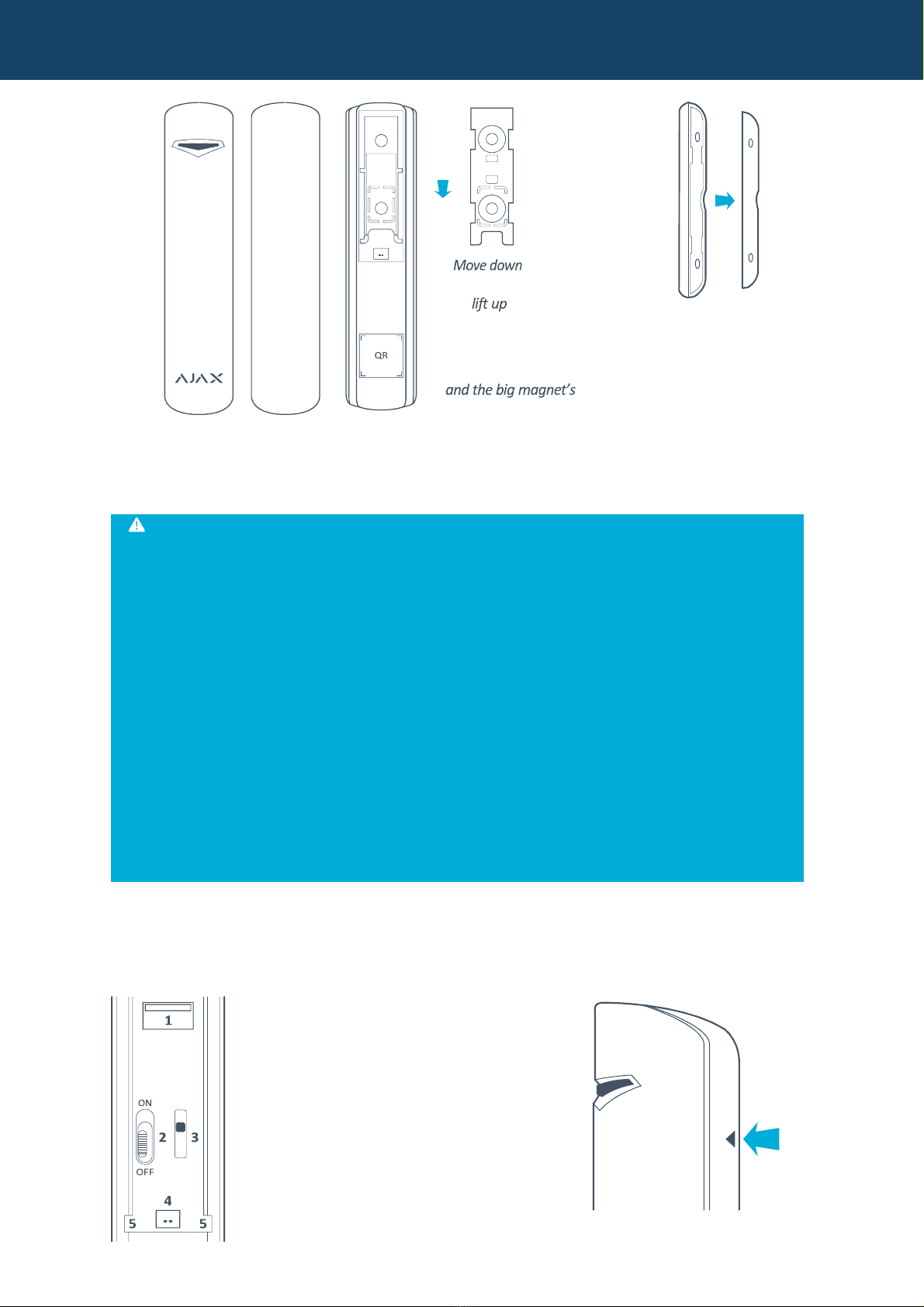
5. INSTALLATION
5. In order to assemble the sensor and the big magnet, lift up the plastic SmartBracket
panel with your fi nger (PICTURE ), move it alongside the frame and remove it.
In order to assemble the small magnet, take its fastening clip out of the frame lifting it up
with a screwdriver (PICTURE 2).
Solar Security
PICTURE
2.
Small
magnet
assembling
PICTURE 1. The sensor’s
5.2 Install the fastening clip
SmartBracket on the door
frame and door or window
frame and window with a
help of the expansion bolts and self-tapping screws included in the set.
5.3 Put the sensor on the SmartBracket. Once the sensor is fi xed on the SmartBracket, its
light must blink. It means that the tamper on the sensor is shut. In case the sensor does not
blink, the tamper status must be checked at the receiver confi guration software!
ATTENTION!
Small magne fi s be er for he ins alling when he door shu and he door jamb are
perpendicular. Big magne fi s be er for he ins alling wi h he door shu and he
door jamb o be in a single plane. Be careful while ins alling he assembling clip.
Overexer ion while ins alling can cause deforma ion and, as a resul , impossibili y o
ins all he sensor or o i s unreliable fas ening. The main body of he sensor is o be
ins alled on he fi xed par of door frame or window frame, and he magne is o be
ins alled on he moving par of he door or window. The magne is o be loca ed in
parallel wi h he sensor’s main body and opposi e o he special sign ( riangle) on i
(PICTURE 4). Fix he Smar Bracke wi h he se ’s assembling uni s only! O her fi xing
sys em use, for example, self- apping screws of big diame er, can damage fas ening
clip. Toge her wi h self- apping screws, here is a double s ick ape in he se . I can
be used for emporary sensor fi xing only. I is recommended no o use he ape for
he permanen fi xing, as he ape is drying up over a ime and he sensor may fall
down which can cause alarm ac ua ion.
5.4 The opening detection sensor is installed!
5.5 In order to connect an additional wire sensor, plug in its wire to the socket “4” (PICTURE
3) on the sensor, and pass the wire through the sensor’s opening having removed the cover
“5” (PICTURE 3) from the sensor.
1– Front cover trigger
2– Cut off switch
3– Tamper button
4– Socket for wire sensors
5– C over on the sensor for the wire
sensors’ wires
fastening
clip
and
Solar Security
PICTURE 3. PICTURE 4.
The sensor’s back cover Triangle detecting the sealed contact
5.6 The longer the wire of the removable sensor is, the bigger are the risks of its accidental
damage and the lower is the coverage quality. The distance suggested between the
removable sensor and the wireless sensor Ajax is no more than m (3.3 ft)
6. MAINTENANCE
6. Maintenance is done once every 6 months. The sensor’s board must be cleared of dust,
spider web, and other impurities.
6.2 Never rub the sensor with substances containing alcohol, acetone, petrol and other active
solvents.
6.3 Replace the batteries up to date. If the battery level is low, the sensor sends an
appropriate signal to the alarm system receiver unit. When the battery has run down, with
detection, including the tamper triggering, the sensor together with a usual indication turns
on its light and turns it off placidly. In order to replace the battery, lift up the trigger “ ”
(PICTURE 3) and remove the sensor’s front cover. Replace the «battery» (PICTURE 5) with a
new one, type CR 23A.
PICTURE 5. The sensor with the back cover removed.
ATTENTION!
The sensor’s au onomous work dura ion depends on he sensor’s riggering frequency
and he ba ery quali y. Wi h door opening 10 imes per day and he 60 seconds of
sampling ime, he ba ery life is 7 years. Wi h door opening 60 imes per hour and 12
seconds of polling period, he ba ery life of he new ba ery is approxima ely 2 years.
7. WARRANTY
7. The sensor’s warranty period is 24 months. The warranty does not cover the battery!

Other AJAX Accessories manuals

AJAX MotionCam User manual

AJAX

AJAX MotionCam User manual

AJAX Socket Type F User manual

AJAX

AJAX Socket Type F User manual

AJAX MotionProtect Fibra User manual

AJAX

AJAX MotionProtect Fibra User manual

Popular Accessories manuals by other brands

DirekTronik LWL02 user manual

DirekTronik

DirekTronik LWL02 user manual

MSR PolyGard 2 SC2 Series user manual

MSR

MSR PolyGard 2 SC2 Series user manual

Hukseflux SR30-M2-D1 user manual

Hukseflux

Hukseflux SR30-M2-D1 user manual

SKIKE V07 PLUS user manual

SKIKE

SKIKE V07 PLUS user manual

Zipato ne-nas-pd01z Quick installation guide

Zipato

Zipato ne-nas-pd01z Quick installation guide

Fiamma F45L Installation and usage instructions

Fiamma

Fiamma F45L Installation and usage instructions

SkyLink HA-318T Guide manual

SkyLink

SkyLink HA-318T Guide manual

QSC ALK-MD2 user guide

QSC

QSC ALK-MD2 user guide

Dreamland Intelliheat Overblanket operating instructions

Dreamland

Dreamland Intelliheat Overblanket operating instructions

Philips VSS3901/00 user manual

Philips

Philips VSS3901/00 user manual

Klarstein 10032885 manual

Klarstein

Klarstein 10032885 manual

SolarEdge SEHAZB-SCKT-MTR-XX installation guide

SolarEdge

SolarEdge SEHAZB-SCKT-MTR-XX installation guide

Munson Healthcare Cybex Weight Machine manual

Munson Healthcare

Munson Healthcare Cybex Weight Machine manual

OTIS OI-7543 Assembly

OTIS

OTIS OI-7543 Assembly

Snowflake SBU15HL Service manual

Snowflake

Snowflake SBU15HL Service manual

Emerson Rosemount 628 quick start guide

Emerson

Emerson Rosemount 628 quick start guide

Emerson Rosemount 8700 Series Quick installation guide

Emerson

Emerson Rosemount 8700 Series Quick installation guide

Anker A1211 quick start guide

Anker

Anker A1211 quick start guide

manuals.online logo
manuals.online logoBrands
  • About & Mission
  • Contact us
  • Privacy Policy
  • Terms and Conditions

Copyright 2025 Manuals.Online. All Rights Reserved.