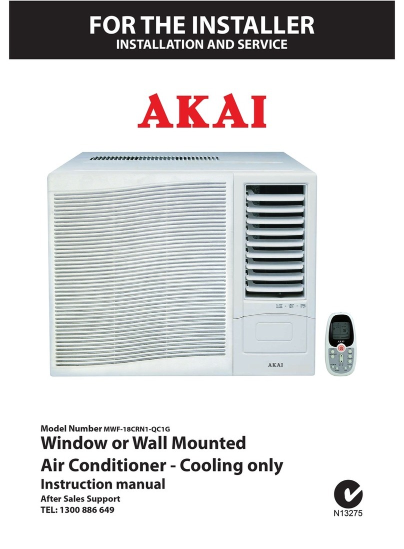
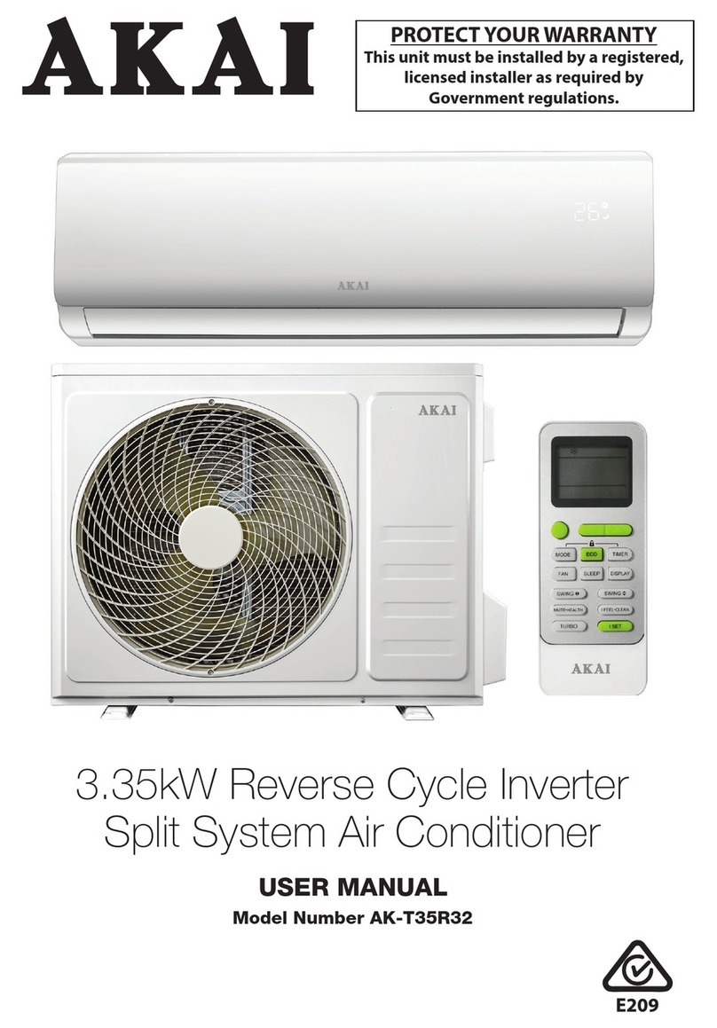
Akai AC-ZP112 User manual

English

Table of Contents
1. Accessories ------------------------------------------------------------------------1
2. Introduction--------------------------------------------------------------------------2
3. Working Principle---------------------------------------------------------------- 3
4. Technical Specification----------------------------------------------------------4
5. Structure----------------------------------------------------------------------------5
. Operation---------------------------------------------------------------------------
7. Maintenance----------------------------------------------------------------------15
8. Trouble Shooting----------------------------------------------------------------18
9. Safety Cautions-----------------------------------------------------------------19
10. Special Guide Line--------------------------------------------------------------20
11. After Sale Service---------------------------------------------------------------21
12. Electric Circuit Drawing--------------------------------------------------------22
Notice: Any maintenance should be returned to the dealer or factory!
Attention: Please read this instruction carefully before use.

Accessories
1 inner air exhaust adaptor -------------------------------------------------------1 pc
2 air exhaust duct ---------------------------------------------- --------------------1 pc
3 adaptor ------------------------------------------------------------------------------1 pc
4 mounting duct ---------------------------------------------------------------------1 pc
5 window kit --------------------------------------------------------------------------1 pc
cap cover ---------------------------------------------------------------------------1 pc
7 remote controller -----------------------------------------------------------------1 pc
8 instruction manual ---------------------------------------------------------------1 pc
9 water plate ----------------------------------------------------------------------- 1 pc
-1-

Introduction
This mobile air conditioner is a new generation air conditioner which is
ideal for using in bedroom, study room, lobby, office, meeting room, warehouse
attics, sports hall and other entertainment room. Its flexibility characteristic enables
easy adjustments to desirable room temperature and humidity. Besides, the built-in
filter can remove floating dust, purify air to create a healthy working environment.
It is designed under ”novelty, practicality and convenience” principles to
satisfy the needs for convenient, efficient and mobile small size air conditioner. The
part makes the cooling special obvious. It features easy using, no need for
installation and convenient maintenance.
The unit is highly competitive to other cooler capable products. With tidy structure,
multiple functions and reasonable ventilation design, the unit minimizes noise and
power consumption.
Thank you for choosing our mobile air conditioner.
This instruction manual is for reference only and does not constitute a contract.
We reserve the right to technical change without prior notice
-2-

Working Principle
Refrigerant with low temperature and low pressure is compressed by the
compressor to high temperature and high pressure vapour, then cools in the
condenser (This is a forced air cooling process: room air passes condenser surface,
absorbs the refrigerant's heat in the condenser by heat exchange, then the room air
warms up and the warm air is exhausted through the air exhaust duct,) to become
high pressure liquid. The liquid flows through capillary tube to lower its pressure to
become low temperature low pressure liquid. After absorbing the heat of air in the
surface of evaporator (A forced air cooling process too: room air passes evaporator
surface, its heat is absorbed by refrigerant in tube, it cools down and flows into room
to lower the room temperature). The low temperature low pressure liquid is
evaporated in the evaporator. The refrigerant becomes vapour and flows back to
compressor. Then the refrigerant vapour is compressed in compressor again. Thus
the room temperature is lowered by circulating this operation.
fan motor
hot air
air flow2(air inflow from back)
condenser
compressor
upper fan
cool air
(heating)
lower fan
motor
lower fan
capillary
tube
air flow1
evaporator
-3-

Technical Specification
Unit specifications:
Model AC-ZP112
Cooling Capacity ( Btu / h ) 12000
Dehumidifying Capacity ( L / day ) 24
Power consumption( W ) 1200
Flow Volume (m
3
/ h )
480
Sound pressure level dB(A) ≤55
Net Weight ( Kg ) 33
Body ( mm ) 738*44 *377
Dimension
Package ( mm ) 8 0*4 0*450
Refrigerant R407C
Note:
1. The above cooling capacity measured at ambient temperature Db 27°C/19°C
Wb 27°C/19°C. (indoor and outdoor , the same)
Db means Dry Bulb ( that is testing in dry environment)
Wb means Wet Bulb ( that is testing in wet environment)
2. Noise level is measured at the point where 1.0 meter away from the front of the
machine. In cooling mode.
3. Air exhaust duct tore down, pump work, fan power consumption is measured
when fan runs at highest speed.
4. Specification listed above is for reference only. Please see actual data printed on
the label.
- -

Structure
1. Control panel 2. Air outlet 3. Handle 4. Caster 5. Air filter
. Air inlet 7. Exhaust air outlet 8. Cord Hanger 9. Water stopper
9
7
8
5
10. Inner air exhaust adaptor-connect with air exhaust duct (11) and exhaust air
outlet (7) 11. Air exhaust duct 12. Adaptor 13. Mounting Duct 14. Window
kit 15. Water plate 1 . Remote controller
13
12
11
10
15
1
14
ON/ OF F
/°
℃
-5-

Operation
1. Control panel
AC-ZP112
2.On/Off switch button
Press On/Off button once the power is on, the unit will run at auto mode.
Press On/Off button while the unit is running, the unit stops, and timer
setting is canceled, other information (mode, set temp, and fan speed)
remain in the machine.
3. Mode button
Press Mode button, unit run mode will change at sequence of: AUTO, COOL,,
DEHUMIDIFY and To should of the LED light is bright.
4. FAN SPEED button
Press SPEED button, unit run mode will change in sequence of: HIGH, MID, LOW
and to should of the LED light is bright.
5. TEMP UP, DOWN button
Press TEMP button to adjust desired room temperature and it will display
in LED window correspondingly, the temperature adjustment range is 15°C--31°C
(0-90°F). When unit is setting at AUTO running mode, the default cooling
temperature is 23°C(8°F).
Press the TEMP UP、DOWN button at the same time,the temperature display will
be shown between °C and °F.
. TIMER button
TIMER OFF:
When unit under running mode, press timer button to set desire OFF time,
time set from 0.5 hour to 12 hours, the timer setting will display in LED window
correspondingly
TIMER ON:
When unit is ready, press TIMER button to set desire ON time, time set
from 0.5 hour to 12 hours, the timer setting will display in LED window
correspondingly
7. SWING button
When unit under running mode, press swing button to auto adjust a right and left
direction of wind.
-6-
1
2 5 3
4
6
7

Operation
Remote control:
::
:
Please point the controller transmission section to the signal receiver
on the unit panel. Indicator lights on the machine control panel can display AUTO,
COOLING, FAN, DEHUMIDIFYING, SPEED, TEMPERATURE, TIMER etc
information.
O N / O F F
Swing Button:
Ipress swing button to
auto adjust a right and left
direction of wind
Fan speed Button:
Press once can
change fanspeed at
sequence of Low,M id
and High speed.
ON/O FF Button:
Press once to
start,and press
again to stop.
Mode Button:
Press once will
change the unit run
mode.
Timer Button:
Unit can be auto OFF if the
unit is under running and
the unit is ready.
Temp Button:
Press this button "+" once
setting room tem perature
will increase 1
℃
.
Press this button "-" once
setting room tem perature
will decrease 1
℃
.
TIM ER
_
SPEED
+
SW IN G
MODE
/ °
℃
F
/ °
℃
F Button
Every time press this
botton, the m achine
control panel shows the
temperature in
°
C or F
on the conversi
Remote control (Auto mode)
The microprocessors control the compressor and fan motor on or off according
To the room temperature to keep the room comfortable.
Please notice the anode and cathode while mounting the batteries.
/ °℃
F
MO DE
S W IN G
+
SPEED
_
TIM ER
2.Press MODE
button to choose
AUTO m ode.
1.M ount batteries
and press
ON/OFF,the system
starts to run.
-7-
Corrosion,oxidation,battery-leaka
ge and any other
gradually acidic defect of this
nature will invalidate the
guarantee.

Operation
Remote control (cooling mode)
Setting temperature range 15°C—31°C(0-90°F).
When the room temperature sensor’s temperature is higher than the set
temperature, the compressor starts to run.
When the room temperature sensor’s temperature is lower than the set
temperature, the compressor stops and fan operates at original speed.
TIM ER
_
SPEED +
SW IN G
MODE
/ °
℃
F
1. Press ON/OFF
button, the system
starts to run.
2.Press Temp
button to set the
desired room temp.
3.Press MODE
button, choose
cooling mode.
4. Press SPEED
button, set fan
speed.
Remote control (Fan mode)
/ °
℃
F
M O D E
SW ING
+
SP EED
_
T IM E R
2. Press MODE button,
choose Fan m ode.
1. Press ON/OFF
button,
the system starts to run.
3. Press Speed button,
choose desire fan speed.
Fan mode: the compressor and lower fan motor stop, upper fan run at set
speed, in this case, temperature setting becomes invalid.
-8-

Operation
Remote control (dehumidifying mode)
Dehumidifying mode: the compressor and lower fan are running and the upper fan
is running at low speed.
/ °
℃
F
MOD E
S W IN G
+
SPEED
_
TIM E R
2.Press MODE
button to choose
DEHUM IDIFYING
mode.
1.Mount batteries
and press
ON/O FF,the
system starts to
run.
Remote control (Timer)
TIMER
_
SPEED
+
SWING
MODE
/ °
℃
F
1. While the unit is under running, press
Timer button to set unit auto OFF time.
3. When set auto OFF
time at 12 hours, pressTimer button once
more, set OFF time will be canceld.
4. When the unit is not under running,
press Timer button to set auto ON time.
2. Press Timer button once, set auto
OFF time will change 0.5 hour from
0.5 hour to 12 hours.
5. press timer button once, set auto OFF timer will change 0.5 hour to
12 hours
. when set auto ON timer at 12 hours, press timer button once more, set
ON time will be canceled.
The unit must connect with power supply to start to set auto ON.
-9-

Battery Operation
Please notice the anode and cathode while mounting the batteries.
We suggest using alkaline batteries.
If the battery is to be replaced or thrown away, the batteries must
be removed and dispose of in accordance with the current laws as it
represents an environmental hazard.
Remote control inserting the batteries
1. slide the cover as shown in figure.
2. insert two new non-rechargeable batteries, being careful to place
them in the correct position(+) and (-).
3. put the cover back on, letting it slide into its original position.
4. the display will show all of the remote control’s symbols for
several seconds.
The operation of Air exhaust duct assembling
M ou n ting du ct
Adaptor
Air exhaust duct
Inn er air exhaust adaptor
21
3
45
-10-

Operation
Air exhaust duct
The unit is called mobile air conditioner, it is movable from one room to
another conveniently. You can use the following method to exhaust the
hot air.
1. exhaust heat from window (see figure A)
Open window for a small angle to put bend mounting duct and fit it on the
window.
≥
≥50cm
≥50cm
A
≥50cm
B
2. exhaust hot air from the door (see figure B)
Open door to an appropriate angle to fit air exhaust duct outside. For the wide open
using, air exhaust duct can put on ground directly. When not
Using the unit, unassembled air exhaust duct from unit and store it carefully
-11-

Operation
Window kit installation(Take the example with three parts of tracks.)
1. Loose nut anti clockwise and unscrew such as Fig 1.
2. adjust the washer on board 1 at the sliding groove on board 2, and then insert the
fixation board 2 in the fixation board 1 such as fig.2
3. adjust according to own window size and fix nut on the fixation board 1
clockwise such as fig.3
-12-

Operation
Window kit installation
Your window kit has been designed to fit most standard “vertical” and
“Horizontal” window applications. However, it may be necessary for you
to improve/modify some aspects of the installation procedures for certain
types of window.(Take the example with three parts of tracks.)
Please refer to see the figures for minimum and maximum window openings.
Win dow S lider K it
M in im u m :58cm
M axim u m :1 2cm
H or izon tal
win dow
≥50cm
≥50cm
Per pen d ic u la r
win d ow
Win dow S lider K it
M in im u m :58cm
M axim u m :1 2cm
≥50cm
≥50cm
-13-

Operation
Air exhaust duct connection
1. air exhaust duct can be extended from 0.5 to 1.5 meters, the unit
works more efficiently while the air exhaust duct is shorter.
2. please make sure the air exhaust duct is not distorted, or flow back
the hot air to increase the temperature of the body. If so, the unit will
stop running automatically
3. please make sure not to use other type of air exhaust duct, or over extend
the exhaust duct. Otherwise the unit working efficiency will decrease.
-1 -

Maintenance
Turn off the unit before cleaning, make sure all sockets are pulled out.
Do not use chemical solvent (like benzene) to clean the unit surface, or the
unit surface will be easily scratched, damaged, even casing could be deformed. If
the air filter is blocked with dust, the airflow volume will decrease. It is better to clean
the filter for every two months
Open the air filter
Take out the air filter cover from back air inflow vent.
Air Filter
Clean:
Wash the air filter gently with warm water, with a neutral detergent, and dry it
thoroughly in a shaped place.
Mounting:
Insert the air filter cover into air flow vent
Clean the unit surface by using little damp soft cloth, then dry it with a duster.
-15-

Maintenance
Drainage:
When unit running in cooling mode, mostly the water can be drained out through the
exhausted hose, however, if the environment is too humid, condensed water can not
completely be drained out by this way. In this case, we need to drain the water.
While water tray is full, error code “E4” will appear in display, meanwhile, the cooling
mode will stop running automatically, and fan will stop in 3 minutes accordingly as
well. If want to start cooling mode, please use the following way to empty the water
Drainage Hole
Rubber Plug
Drainage Knob
Water Plate
A. water plate drainage
1. turn off the unit
2. horizontally place water plate underneath drainage hole;
3. disconnect drainpipe through drainage knob and rubber plug, water will
Automatically flow out;
4. when the water is empty, push rubber plug back to the drainage hole;
5. connect drainage pipe by spinning the knob;
. restart the unit
Normally it is no need to drain the water because the unit has the water pump to
pump the condensed water from the water tray onto the condenser to evaporate the
water unless the air is too humid.
-16-

Maintenance
B.Connect drainage
1. disconnect drainage knob and the rubber plug;
2. connect supplied drainage pipe to drainage hole, water will flow out
automatically;
3. if you want to extend drainage pipe, you can use 18mm(diameter)
plastic pipe and connect with the drainage pipe.
Ru bber Plu g
E xtend D rain age Pipe
(D iam eter:18 mm)
D rainage Pipe
D rainage K nob
D rainage Pipe
Important notice
1. in order to extend the life of the product, please drain all the condensed
water while not use the unit for some time;
2. the unit adapts auto drainage system; please pay attention the signals on
display when the air is too humid. (above 90% humidity)
-17-

Trouble shooting
Before asking for repair, please check:
PROBLEMS CAUSES SUGGEST SOLUTIONS
The unit does not
work
Power supply fault:
1. Not plug in;
2. Bad plug or socket;
3. Fuse broken or wire
broken;
1. Plug in correctly;
2. Change the plug or the socket;
3. Send the unit to service center to
change the fuse ;( fuse: 3.15A
250V )
The unit stop running
automatically
Timer is set or room
temperature is lower
than set temperature;
Close the TIMER or wait for it to
run automatically;
In cooling mode, no
cool air coming out;
Room temperature is
lower than set
temperature;
Make the setting temperature lower
than the room temperature; if it still
does not work, call the local
technician for repairing
Error code "E1" in
LED window
Environment
temperature sensor
is broken.
Replace the temperature sensor
Error code "E2" in
LED window
temperature sensor on
the evaporator is
broken
Replace the sensor
Error code "E3" in
LED window
Cooling system
malfunction caused by
the lack of refrigerant
Contact the local repairing
technician directly
Error code "E4" in
LED window the red
FULL light is bright
Water tray is full in the
heating mode, but the
unit is still working
Empty water in water plate
-18-
Table of contents
Other Akai Air Conditioner manuals

Akai
Akai AUS-12H53R150P9 User manual

Akai
Akai AK-9000-RC User manual

Akai
Akai TAK-9000-25 User manual

Akai
Akai AK-12000-RC User manual

Akai
Akai TEM-35CHSABH User manual

Akai
Akai MISTRAL912Dual-R32-K User manual

Akai
Akai AK-9000-F User manual

Akai
Akai AK-T51R32 User manual

Akai
Akai MWF-18CRN1-QC1G User manual
Akai
Akai MWF-18CRN1-QC1G User manual
Popular Air Conditioner manuals by other brands

GE
GE AHE18 Series Owner's manual and installation instructions

Mitsubishi Electric
Mitsubishi Electric MSC-GE20VB operating instructions

Frigidaire
Frigidaire LRA257ST21 Use & care guide

DeLonghi
DeLonghi EX Series Instructions for use

Carrier
Carrier DB-O Series Use and maintenance

Toshiba
Toshiba RAV-RM561KRTP-E installation manual