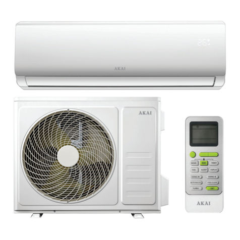
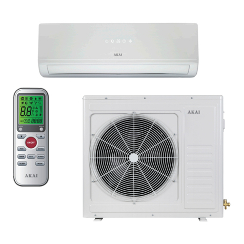
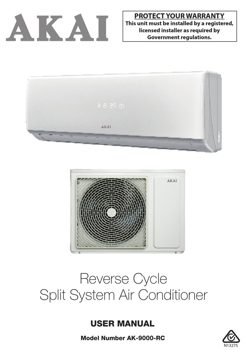
Akai AK-9000-RC User manual

Model Number AK-9000-RC
Reverse Cycle Split System
Air Conditioner
INSTALLATION MANUAL
PROTECT YOUR WARRANTY
This unit must be installed by a registered,
licensed installer as required by
Government regulations.
N13275

2
Contents
Important Safety Instructions 3
Product Overview 5
Selecting the Installation Place 6
Installation 8
Technical Specifications 19
After Sales Support
1300 886 649 | info@tempo.org

3
Important Safety Instructions
FOR THE INSTALLER
Read this guide before installation. The appliance must be installed by
a professional installer according to the instructions in this manual and
in accordance with all applicable regulations.
Electrical connections
• All wiring work must be done by a qualified electrician in accordance with
national wiring regulations.
• The mains voltage must be in the range of 90-110% of that stamped on the
rating plate. The switch or power plug must be kept clean.
• Before accessing the terminals, all the power circuits must be disconnected
from the power supply.
• All wires must be connected correctly, otherwise the unit will malfunction and
cause damage to the air conditioning system.
• The air conditioner must be grounded. Incomplete grounding may result
in electric shocks. Do not connect the earth wire to the gas pipeline, water
pipeline, lightning rod or telephone earth wire.
• An earth leakage breaker with a rated capacity of more than 1.5 times the
maximum current must be installed to avoid possible electric shocks.
• If the air conditioner is not fitted with a supply cord and a plug, an all-pole
switch must be installed in the fixed wiring and the distance between
contacts should be no less than 3mm.
• If the power supply cord is damaged, it must be replaced by the
manufacturer or its service agent or a similar qualified person in order to
avoid a hazard.
• For the method of connection of the appliance to the electrical supply and
interconnection of separate components, please see the electric connection
elements chart attached to the outdoor unit.
• Make sure that after installation the power plug can easily be reached.
• If the model has no plug a switch with a contact separation of at least 3mm
in all poles shall be added in the fixed wiring.
PROTECT YOUR WARRANTY
These installation instructions are for use by an appropriately
qualified installer. Do not try to install the air conditioner on your
own; doing so will expose you to danger and void the warranty.
Contact a licensed installer.
After Sales Support
1300 886 649 | info@tempo.org

4
Installation
• The air conditioner’s outdoor unit must be installed on suitably strong
supports.
• During installation of the indoor and outdoor units, do not allow children
access to the working area.
• Make sure that the base of the outdoor unit is firmly fixed, otherwise it will
produce abnormal noise and vibration during use.
• Do NOT install the outdoor unit:
XIn an area where the running noise could disturb neighbours
XIn environments where the air could contain gas, oil or sulphur
XNear sources of heat
XAt a distance of less than 1m from flammable substances (e.g. alcohol or
other flammable liquids or gases) and pressurised containers (e.g. spray
cans).
• If the appliance is used in areas without the possibility of ventilation,
precautions must be taken to prevent any leaks of refrigerant gas from
remaining in the environment and creating a fire danger.
• Check that air cannot enter the refrigerant system and check for refrigerant
leaks when moving the air conditioner.
• Carry out a test cycle after installing the air conditioner and record the
operating data. Make sure that air cannot enter the refrigerant system and
check for refrigerant leaks when moving the air conditioner.
Important Safety Instructions (Cont.)
After Sales Support
1300 886 649 | info@tempo.org

5
After Sales Support
1300 886 649 | info@tempo.org
Product Overview
Indoor Unit
1 Air return grid
2 Operational performance
indications
3 Adjustment fin for left/
right airflow direction
4 Adjustment flap for up/
down airflow direction
5 Air outlet
6 Air filter
7 Drain tube
Outdoor Unit
8 Air inlet
9 Air discharge vent
10 Refrigerant pipe
connection and electric
wiring cord
This Air Conditioner is made up of an indoor unit, outdoor unit and a
remote control. The indoor unit is installed on a wall of the room to be air
conditioned. The outdoor unit is installed in a protected area outdoors, on
the ground or on a wall on suitable brackets.
NOTE:
• If the power is supplied from the outdoor unit, the power supply cord is
fitted in the outdoor unit.
• Figures and descriptions throughout this user manual are for explanatory
and illustrative purposes only and may differ slightly from the appearance of
the product purchased.
d
1 2
3 4 5 6
7
8
9
10
Fig. 1
Fig. 2

6After Sales Support
1300 886 649 | info@tempo.org
Selecting the Installation Place
Indoor unit
This Air Conditioner (9000 BTU) is suitable for cooling or heating a room of
up to 22m2in size. Before starting installation, decide on the position of the
indoor and outdoor units, taking into account the minimum space required
around the units.
Install the indoor unit:
3Level, on a strong wall that is not subject to vibrations
3Near an electrical socket or private circuit
3So that the inlet and outlet ports are not be obstructed, the air should be
able to blow all over the room
3Where the minimum clearances can be maintained (Fig.1) and at least
2.30m above floor height
3Where connection between the indoor and outdoor units is as easy as
possible.
Do NOT install the indoor unit:
2Near a source of heat, steam or flammable gas
2Near a doorway
2Where it will be exposed to direct sunlight or affected by the outdoor air
2Where it will be affected by oil fumes or splashes, smoke or steam
2Near high-frequency facilities (such as high frequency arc welders, etc.)
2In areas where acid solutions or special sulfide sprays are frequently used
2Above musical instruments, TVs, computers or other valuable appliances
2Where the air outlet of the indoor unit would be near a fire/smoke alarm (during
operation, warm air from the unit might erroneously trigger the alarm).
NOTE: If additional function devices are to be installed above the air conditioner,
make sure to leave the extra required space for such devices.
Above 100mm(4")
Left side: 150mm(6")
and above from wall
Right side: 150mm (6")
and above from wall
Ceiling
Wall hanging plate
ground
2300mm(7'6")
and above
Fig.1

7
After Sales Support
1300 886 649 | info@tempo.org
Selecting the Installation Place (Cont.)
Height limits of indoor and outdoor units
Make sure to maintain the below height limitations (Fig.2) when installing the
indoor and outdoor units.
• Either the indoor unit or the outdoor
unit can be installed higher, as long
as the height differences comply
with the above stated requirements.
• Try to keep pipe bends to a
minimum so as to maintain
maximum performance of the units.
Outdoor unit
If you put up a canopy to protect the outdoor unit from rain and sun rays,
make sure you do not create any obstacles for proper heat dispersion from
the condenser.
Install the outdoor unit:
3In a safe place and solid place that can support the weight of the unit
3Level, on a strong and secure installation base and metal supporting frame
3Where the air discharge and operating sound level will not disturb
neighbours
3Where condensation water is easily drained from the base plate
3Where the minimum clearances can be maintained (as listed on page 8) for
free air circulation.
Do NOT install the indoor unit:
2Near sources of heat, steam, flammable gas or toxic gas
2Where it is exposed to high winds or excessive dust
2Where it will be exposed to rain, direct sunshine or strong sea breezes —
if such position cannot be avoided, use a protection that will not interfere
with the airflow
2Where people often pass
2Where animals are kept or plants are grown, as exposure to cold and hot
air will affect them
2Where it will be subject to vibration.
Fig.2

8
Installation
After Sales Support
1300 886 649 | info@tempo.org
Detailed space requirements around the outdoor unit
500mm(1'8") min
100mm(4") min
500mm(1'8") min
200mm(8") min
500mm(1'8") min
500mm
(1'8")min
200mm
(8")min
Space for maintenance
200mm(8") min
300mm(1') min
1000mm(3'4") min
100mm(4") min
Fig.3 Fig.4 Fig.5
Fig.6
Fig.7
Fig.8
The above listed clearances must be maintained:
1. When there are obstacles above the unit (Fig.3).
2. When the front (air outlet) is open (Fig.4).
3. When there are obstacles only in the front (air outlet) (Fig.5).
4. For maintenance (Fig.6) of the unit.
5. When there are obstacles at the front and rear sides. (Fig.7).
6. When there are obstacles all around the unit, on four sides (Fig.8).
The outdoor unit must NOT be installed when there are obstacles all
around the unit, even if the top side is open. At least two sides must
be kept open.

9
Installation (Cont.)
After Sales Support
1300 886 649 | info@tempo.org
Installation of the indoor unit
The pipes can be connected as illustrated in Fig.9. When the pipes are
connected to exit at the sides of the unit, a groove for the pipes has to be
opened at the proper place on the base stand.
Installing the wall-mounting plate
Fix the wall-mounting plate firmly on the wall with screws. Make sure the
plate is installed level, a slanted wall-mounting plate might jeopardise the
smooth discharge of condensation water.
G
Rear outlet
GLeft rear outlet
GLeft outlet
G
Right outlet
GBottom outlet
Fix with a tape
Wall cap Wall pipe
Interior Exterior
5-10mm
lower
(1/5-2/5")
Wall
Pipelines of indoor unit
Drain pipe
Rear pipe
Bottom hooks
Hook supports
Top hooks
Fig.9
Fig.10
Fig.11
Fig.12
Drilling holes
Drill holes with a diameter of 65mm
slightly below the wall-mounting
plate, making sure the outer edge of
the hole is 5-10mm lower (Fig.10) so
that condensation water can flow out
smoothly.
Cut the pipe that penetrates the wall to
the proper length; it should be 3-5mm
longer than the wall thickness, then
insert the pipe as illustrated (Fig.10).
Installing the drain pipe
Install the pipes of the indoor unit
in accordance with the direction of
the wall holes. Wrap the pipes and
drain pipe tightly together with tape,
making sure that the drain pipe is
underneath the pipes (Fig.11). (When
the drain pipe passes the room interior,
some condensed water drops may
accumulate on the pipe surfaces if the
humidity is very high.)
Installing the indoor unit
Pass the connection wires, connecting
pipes and drain pipe through the wall
hole. Hang the indoor unit on the hooks
at the top of the wall-mounting plate
so that the hooks at the bottom of the
indoor unit match the hooks of the wall-
mounting plate (Fig.12).

10
Installation (Cont.)
After Sales Support
1300 886 649 | info@tempo.org
Inspections
• Check if the hooks at the top and
bottom are firmly fixed.
• Check if the position of the master unit is
properly levelled.
• The drain pipe should not curve
upward (Fig.13).
• The drain pipe should be at the lower
part of the wall pipes (Fig.13).
Installation of the outdoor unit
• Try to ship the product to the installation location in its original package.
• During shipping, the outdoor unit must not be slanted to over 45 degrees.
(Do not store the unit in a horizontal way.)
• As the gravity centre of the unit is not at the installation centre, special
caution should be taken when using hoisting cables to lift it up.
• Use expansion bolts to fix the mounting supports on the wall.
• Use bolts and nuts to fix the outdoor unit firmly on the supports and keep
on the same level.
• If the unit is to be installed in areas with strong wind, such as in coastal
areas or at places high above sea level, or on a rooftop, the outdoor unit
should be installed against a wall and the supports firmly fixed to ensure
normal fan operation.
• If installing parellel units, make sure to maintain the clearances below
(Fig.14).
Drain pipe
Connecting wires
Connecting pipe
Wall pipe
Drain pipe
Fig.13
300mm(1')min
Fig.14

11
Installation (Cont.)
After Sales Support
1300 886 649 | info@tempo.org
Pipe connection and air purging *
* The following pipe connection and air purging instructions are only suitable
for air conditioner models other than quick coupler models. Instructions for
quick coupler models follow on page 13.
The air conditioning system must be installed in way that ensures that no
dust, foreign articles, air or moisture can enter the system. Pay particular
attention when connecting the pipes for the outdoor unit.
• Try to avoid repeated curves as much as possible, otherwise the copper
pipes may harden or crack.
• Use suitable wrenches for connecting the pipes so as to ensure appropriate
torque. Refer to the torque table below for torque values (Table 1).
Excessive torque might damage the joints while too little torque might lead
to leakage.
Table 1: Torque values, based upon the wrench to be used

12
Installation (Cont.)
After Sales Support
1300 886 649 | info@tempo.org
Fig.15
Air purging with a vacuum pump
After having connected the indoor and
outdoor units, make sure all pipes have
been properly connected, then bleed the
air and humidity from the refrigerant circuit
by following the below steps.
1. Remove the charging port cap and
connect the manifold gauge and the
vacuum pump to the charging valve by
service hoses, as illustrated (Fig.15).
2. Open the valve of the low pressure side
of the manifold gauge, then run the
vacuum pump. Vacuum the indoor unit
and the connecting pipes for about 10
minutes until the pressure in them has
dropped to below 1.5mmHg. When
the desired vacuum has been reached,
close the low pressure valve of the
manifold gauge and stop the pump.
3. Disconnect the service hoses and fit
the cap to the charging valve.
4. Remove the blank caps and fully open
the spindles of the 2-way and 3-way
valves with a service valve wrench.
5. Tighten the blank caps of the 2-way and
3-ways valves, applying the appropriate
torque as listed on page 11 (Table 1).
Adding refrigerant
Refrigerant must be added if the piping
measures more than 5 metres in length.
This operation can only be performed by a
professional technician. For the additional
amount of refrigerant required, see the
Table 2 below.
Table 2:
Piping length: 5m x 30g
(or 16ft x 0.3oz)
Piping length: 5m x 65g
(or 16ft x 0.7oz)

13
Installation (Cont.)
After Sales Support
1300 886 649 | info@tempo.org
Gas leakage inspection
After the pipeline connection is done, use a leakage inspection device or
soap suds to carefully check if there is any leakage at the joints. This is
an important step to ensure the quality of installation. Once a leakage is
detected, proper treatment should be taken immediately.
Pipe connection for split type quick coupler models
If you have purchased the air conditioner for split type quick coupler models,
follow the below pipe connection instructions. (This section does not apply to
the AK-9000-RC Air Conditioner.)
1. Remove the dust caps from the indoor and
outdoor units, and the connecting pipe.
2. Align the joint counter of the connecting
pipe with the proper indoor and outdoor joint
conic surfaces and tighten the connecting nut
manually. Then secure the connection with a
wrench (Fig.16), applying the appropriate torque
as listed on page 11 (Table
1).
3. Remove the two valve core
caps from the outdoor unit
(Fig.17).
4. Turn on the high and low
pressure valve cores with a
socket wrench, then tighten
the two valve core caps of
the outdoor unit (Fig.17).
5. Finally, wrap the hot insulating cotton around the joints of the indoor and
outdoor units.
Notes on installation of
quick coupler
• Table 3 lists the
minimum radius
parameters for the
connecting pipe.
• Quick coupler assembly
and disassembly limit:
the assembly and
disassembly times are inadvisably more than 7.
Fig.16
Fig.17
Normal

14
Installation (Cont.)
After Sales Support
1300 886 649 | info@tempo.org
Pipelines connection for whole unit
type quick coupler models
(This section does not apply to the AK-
9000-RC Air Conditioner.)
1. Remove the two screws on the
maintenance plate with a screwdriver
and take off the plate, then remove
the dust caps on both the indoor
male coupler and outdoor female
coupler (Fig.18).
2. To open the inner hooks, apply a little
force with your thumb and press the
projecting section of the outdoor
female coupler backwards, then you
can easily take out the outdoor valve
with the other hand (Fig.19).
3. In the same way, press the projecting
section backwards, then connect the
indoor male coupler to the outdoor
female coupler (Fig.20).
4. Close the key lever of the indoor male
coupler, push it into the horizontal
position (Fig.21). The refrigerant will
start circulating through the indoor
and outdoor units; you should be able
to hear sounds of air flowing through
the system.
5. Connect the outdoor quick cable
coupler with the indoor quick cable
coupler (Fig.22).
6. Finally, re-install the maintenance
plate back into its place
(Fig.23). As for the
outdoor valve for gas
leaking and the dust
caps, you can preserve
them for future possible
use on the removal of
your air conditioner.
Fig.18
Fig.19
Fig.20
Fig.21
Fig.22
Indoor quick cable coupler
Outdoor quick cable coupler
Wrap with ethylene tapes
Fig.23

15
Installation (Cont.)
After Sales Support
1300 886 649 | info@tempo.org
Connection of the power cable
1. Remove the drawer of the outdoor unit.
Finishing touches
• Wrap the pipes tightly with ethylene tape.
• Fix the wrapped pipes on the exterior wall with clamps.
• Fill in the gaps left over by the pipe hole and wall hole to prevent
rainwater from entering.
Test running
• Connect the unit to the power source and check if the function selection
keys on the remote controller are working properly.
• Check if the room temperature adjustments and timer settings are
working properly.
• Check if the drain is smooth.
• Check if there is any abnormal noise or vibration during operation.
• Check if there is leakage of refrigerant.
Fig.24
Fig.26
Fig.25
2. Non-quick coupler:
Connect the indoor power and control
wires with the matching outdoor
wires in accordance with the electric
schematic diagram and make sure that
the connection is firmly done (Fig.24)
Quick coupler:
Directly connect the indoor and
outdoor quick cable couplers after
disassembling the outdoor unit’s
connecting box cover (Fig.25).
3. Use a press plate to fix the wires firmly,
and re-install the drawer.
4. Optional steps:
In some cooling and heating
models you should connect the
indoor wire connector with an
outdoor probe wire connector
for defrosting (Fig.26).

16
Installation (Cont.)
After Sales Support
1300 886 649 | info@tempo.org
Installation checklist
• Check and ensure that the installation place is solid and strong enough to
support the weight of the unit.
• Check and ensure that condensation water can easily drain away.
• Check and ensure that in the vicinity of the unit:
XThere is nothing that prevents ventilation or obstructs operation in front
of the unit.
XThere is suitable protection for the outdoor unit in case of direct
exposure to sea breezes.
XThere is a minimum distance of 1m between the indoor unit and remote
controller and a TV or radio
XThere are no flammable gas leaks.
XThere is no oil splashing.
• Check and ensure that the installation place does not increase the unit’s
operation noise or vibration. If there is a possibility that vibration can be
transmitted to the house, fix the unit by inserting vibration-proof pads
between the unit and fittings.
• Things left near the outlet and inlet of the outdoor unit cause malfunction or
increased operation noise. Do not leave obstacles near the outlet and inlet.
• If irregular sound is heard during operation, consult with the distributor of
the unit using the information at the bottom of the page.
Inspection and maintenance
According to the service conditions and operating environment, the inside
of the air conditioner will become dirty after several seasons (3 to 5 years) of
service, resulting in decreased operating performance.
While the air conditioner may be still be used for a longer period, we
recommend getting the unit professionally inspected and maintained during
an off season, in addition to regular cleaning.
To book a service call, contact our after sales support centre using the details
at the bottom of the page.

17
Installation (Cont.)
After Sales Support
1300 886 649 | info@tempo.org
Troubleshooting guide
This air conditioner is equipped with a self-diagnosis function to help you
identify potential problems. Should you encounter problems with your air
conditioner, contact our after sales support centre using the details on the
bottom of the page. However, before calling for service, consult the self-
diagnosis information below.
Self-check
information
Indicator light self-check
code
Digital self-
check code
Defrost indication Blinks once per second Indicates
“dF”or heating
icon blinks
Anti cold wind Blinks once per second Fan motor
picture not
running
Room temperature
sensor fault
Blinks once every 8 seconds E2
Coil temperature sensor Blinks twice every 8 seconds E3
Indoor fan fault Blinks 3 times every 8 seconds E8
Outdoor feedback Blinks 6 times every 8 seconds E5
External feedback fault Blinks 7 times every 8 seconds E7
Open the door fault Blinks 3 times every 8 seconds E0
Outdoor tube
temperature sensor
faults
Blinks 4 times every 8 seconds E1
(EEPROM)
Communication failures
Blinks 6 times every 8 seconds E6
Outdoor temperature
exceeds scope (too
cold)
Blinks once per second FF

18
Installation (Cont.)
Quick connector installation instruction*
* Only relevant for the installation of stainless quick connector pipes -- this
section does not apply to the AK-9000-RC Air Conditioner
• To expand the connecting pipe, hold one side then expand it following the
right direction.
• Make sure the angles have a radian at some extent while installing the
stainless soft pipe. Angels need to be around, not bent (to the quick
connecting spot and drilled point in the wall).
• To prevent the stainless soft pipe from getting bent or stretched, always fix
these soft connecting pipes while installing them.
After Sales Support
1300 886 649 | info@tempo.org
Table 4
Installation guide
• To keep the allowed bending radius,
take care when unwinding the
packed soft pipes. Do not expand
only one side of the pipes.
• Use a semicircle pulley to maintain
the appropriate bending radius.
Extreme bending could damage the
pipes.
• Use a twisting wheel to avoid
improper bending. Overlength soft
pipes will lead to irregular bending.
• Use a rigid elbow to keep the
bending radius while soft pipes
operating. Undersize bending will
damage the soft pipe.
• Make sure the soft pipe is not too
short so the minimum bending
radius can be maintained.

19
Technical Specifications
After Sales Support
1300 886 649 | info@tempo.org
AK-9000-RC AK-12000-RC AK-18000-RC
Rated Voltage & Frequency 220-240V, 50Hz
Cooling
Capacity 2600W
(1600-3000W)
3500W
(2200-4000W)
5100W
(2800-5500W
Power Input 675W
(420-1160W)
910W
(600-1400W)
1504W
(720-1880W)
Current Input 3.4A
(1.9-5.4A)
4.2A
2.6-6.5A)
7.0A
(3.2-8.5A)
EER 3.85w/w 3.85w/w 3.39w/w
Heating
Capacity 2600W
(1700-3200W)
3700W
(2200-4200W)
5200W
(2900-5700W)
Power Input 700W (430-1190W) 960W (600-1400W) 1480W (730-1920W)
Current Input 3.8A (2.0-5.7A) 4.4A (2.6-6.7A) 6.8A (2.8-8.7A)
COP 3.71w/w 3.85w/w 3.51w/w
Moisture Removal 0.9kg/h 1.3kg/h 1.9kg/hr
Max. Input Consumption 1600W 1800W 2800W
Max. Current 9A 9.5A 13.5A
Com-
pressor
Type Rotary
Capacity 2310W 2615W 5100W
Power Input 915W 1010W 1150W
LRA 22A 22A --
RLA 3 6.5 5.0
Thermal
Protector External External Internal
Refrigerant
Oil Fv50S \320ml FV50S \320ml HAF68D1U or
equivalent 480=20ml
Indoor
Fan
Power Input 27W 47W 56W
Capacity 1µF 1.2µF 1.8µF
Speed
(H/M/L) 1290±30rpm 1300rpm 1300/1150/1000rpm
Diameter *
Length Ø98*622 Ø98*707 Ø102*707
Indoor
Air Circulation 500m3/h 700m3/h 850m3/h
Noise Level 31-41dB(A) 40-44dB(A) 42-46dB(A)
Dimensions
(L x W x H) 800 x 280 x 190mm 900 x 292 x 215mm 900 x 292 x 215mm

20
Technical Specifications (Cont.)
After Sales Support
1300 886 649 | info@tempo.org
AK-9000-RC AK-12000-RC AK-18000-RC
Indoor
Evapo-
rator
Rows/Tubes/
Circuits 2/15/2 2/17 2/20
Tube Pitch/
Row Pitch/Fin
Spacing
21/12.7/1.4mm 21/12.7/1.6mm 21/12.7/1.6/1.7mm
Fin Type Open Window Open Window
Hydrophilic Aluminium Foil
Tube Outside
Ø& Type
Ø7 Internal Thread
Tube
Ø7 Internal Thread
Tube Ø7/R410A
Coil LxHxW 615 x 315 x 25.4mm 705 x 402 x 25.4mm 705 x 326 x 25.4mm
Outdoor
Fan
Motor
Power Input 67W 67W 103W
Capacity 1.5/450µF 1.5/450µF 3µF
Speed
(H/M/L) 850/550rpm 850/550rpm 870/600rpm
Diameter *
Height Ø408*134 Ø408*134 Ø415
Outdoor
Con-
denser
Rows/Tubes/
Circuits 2/24 2/20 2/26
Tube Pitch/
Row Pitch/Fin
Spacing
21/1.56mm 25/21.56/1.5mm 21/18.19/1.6mm
Fin Type Blue Open Window
Hydrophilic Open Window Blue Open Window
Hydrophilic
Tube Outside
Ø & Type
Ø7x0.25+0.18
Internal Thread Tube
Ø9.52x0.28+0.15
Internal Thread Tube
Ø7.0x0.25+0.18
Internal Thread Tube
Coil LxHxW 504 x 936 x 25.4mm 719 x 500 x 21.56mm
753 x 500 x 21.56mm 798 x 546 x 36.38mm
Outdoor: Cooling Capillary/
Heating Aux.Capillary (mm)
Ø3.0 x Ø1.4 x 900
Ø3.0 x Ø1.4 x 250
Ø3.0 x Ø1.4 x 520
Ø3.0 x Ø1.4 x 480
Ø3.0 x Ø1.8 x 900
Ø3.0 x Ø1.8 x 600
Outdoor
Noise Level 53db(A) 54db(A) 55dB(A)
Dimensions
(L x W x H) 812 x 256 x 540mm 811 x 256 x 540mm 850 x 295 x 605mm
Refrigerant
Type/Quantity R410A/1060g R410A/1400g R410A/1420g
Design Pres-
sure (Hi/Low) 4.2/1.3MPa 4.2/1.3MPa 4.2/1.2MPa
Other manuals for AK-9000-RC
1
This manual suits for next models
1
Table of contents
Other Akai Air Conditioner manuals

Akai
Akai AC-ZP112 User manual
Akai
Akai AK-9000-RC User manual

Akai
Akai AUS-12H53R150P9 User manual

Akai
Akai AK-9000WIFI User manual

Akai
Akai AK-T51R32 User manual
Akai
Akai AK-9000-F User manual

Akai
Akai AK-T25R32 User manual

Akai
Akai TEM-35CHSABH User manual

Akai
Akai AUS-12H53R150P9 User manual
Akai
Akai AK-T70R32 User manual