Akai TAK-9000-25 User manual

After Sales Support
1300 886 649 (AUS) 0800 836 761 (NZ) | info@tempo.org
PROTECT YOUR WARRANTY
This unit must be installed by a registered,
licensed installer as required by
Government regulations.
N13275
Reverse Cycle Inverter Air Conditioner
INSTALLATION MANUAL
Model Number
TAK-9000-25
TAK-12000-32
TAK-18000-50
TAK-24000-70

After Sales Support
1300 886 649 (AUS) 0800 836 761 (NZ) | info@tempo.org
2
Contents
03 General Safety Instructions
04 Product Overview
07 Selecting the Installation Place
09 Installation
17 Wiring Diagrams
18 Information for the Installer

After Sales Support
1300 886 649 (AUS) 0800 836 761 (NZ) | info@tempo.org 3
General Safety Instructions
FOR THE INSTALLER
• Read this guide before installing and using the appliance.
• Compliance: Install the appliance in accordance with all applicable regulations.
• No children’s access: During installation of the indoor and outdoor units,
do not allow children access to the working area.
• Do NOT install the unit:
• In environments where the air could contain gas, oil or sulphur.
• Near sources of heat.
• At a distance of less than 50cm from flammable substances (e.g. alcohol or
other flammable liquids or gases) and pressurised containers (e.g. spray cans).
• Ventilation: If the appliance is used in areas without the possibility of
ventilation, precautions must be taken to prevent any leaks of refrigerant
gas from remaining in the environment and creating a fire danger.
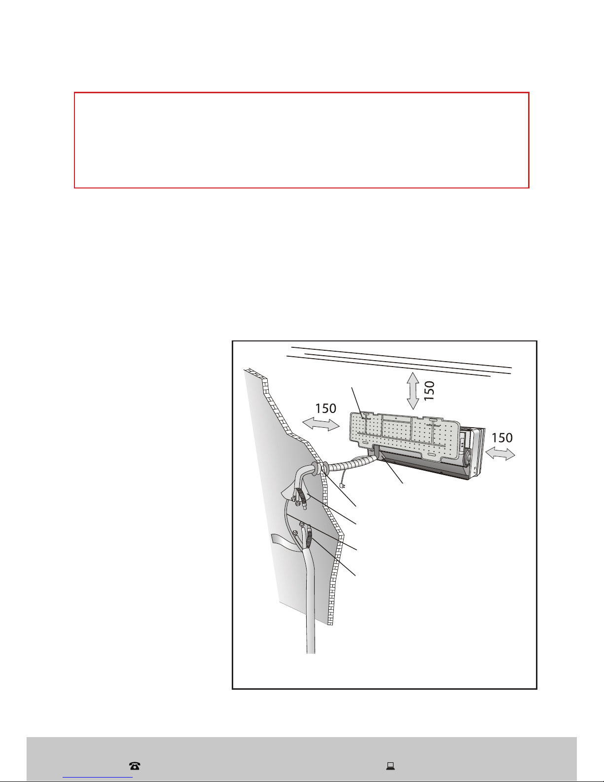
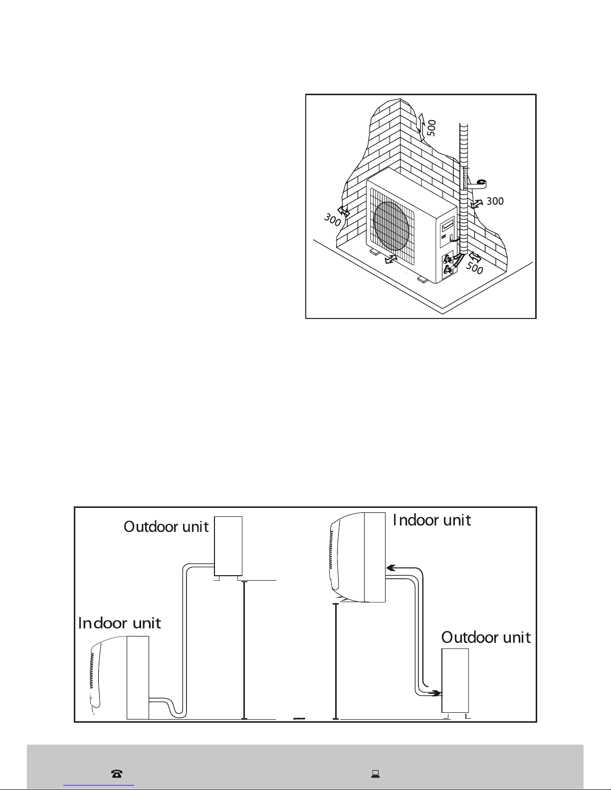
• Outdoor unit: Make sure that the base of the outdoor unit is firmly fixed.
• Disconnect power circuits: Before accessing the terminals, all the power
circuits must be disconnected from the power supply.
• Refrigerant system: Check that air cannot enter the refrigerant system and
check for refrigerant leaks when moving the air conditioner.
• Voltage: Ensure that the mains voltage corresponds to that stamped on the
rating plate. Keep the switch or power plug clean.
• Socket: Check and ensure that the socket is suitable for the plug.
• Fuse ratings: The ratings of the fuse installed in the built-in control unit are
T 5A / 250V.
• Overload protection: The user must protect the indoor unit with a fuse of
suitable capacity for the maximum input current or with another overload
protection device.
• Packaging materials: The packaging materials are recyclable and should
be disposed of responsibly for recycling.
• Test cycle: Carry out a test cycle after installing the air conditioner and
record the operating data. Make sure that air cannot enter the refrigerant
system and check for refrigerant leaks when moving the air conditioner.
PROTECT YOUR WARRANTY
These installation instructions for the Reverse Cycle Inverter Air
Conditioner are for use by an appropriately qualified, licensed
installer. The appliance must be installed in accordance with all
applicable regulations. Do not try to install the Air Conditioner on
your own; doing so will expose you to danger and void the warranty.

After Sales Support
1300 886 649 (AUS) 0800 836 761 (NZ) | info@tempo.org
4
Product Overview
• This Reverse Cycle Inverter Air Conditioner is made up of an indoor and
outdoor unit (Fig. 1 & 2), which are connected through properly insulated
copper pipes (not supplied) and an electrical connecting cable.
• The indoor unit is installed on a wall of the room to be air conditioned.
• The outdoor unit is installed outdoors on the ground, or on a wall on
suitable brackets.
• Technical data of the air conditioner are printed on the labels placed on the
indoor and outdoor units.
12-3
6
4-5
9
11 8
10 7
DIS
PLAY HEALTH Y
3D
ON/O
FF
SWING
F
AN
TI
MER SUPER
SLEEP MODE
ECO
CLOCK
12
10
1
23–4
9 8 7 6
5
Fig. 1
A
Scope of Delivery
(A) Indoor Unit: Parts
No Part
1 Front panel
2 Air filter
3 LED display
4 Signal receiver
5 Terminal block cover
6 Deflectors
7 Emergency button
8 Indoor unit rating label
9 Airflow direction flaps
10 Remote control

After Sales Support
1300 886 649 (AUS) 0800 836 761 (NZ) | info@tempo.org 5
Product Overview (Cont.)
17
15
16
14
12
13
14
15
11
Fig. 2
(B) Outdoor Unit: Parts
No Part
11 Air outlet grille
12 Outdoor unit rating label
13 Cover
14 Gas valve
15 Liquid valve
NOTE:
The diagrams throughout this manual are for illustrative purposes only
and may vary slightly from the appearance of the unit purchased.
B

After Sales Support
1300 886 649 (AUS) 0800 836 761 (NZ) | info@tempo.org
6
Product Overview (Cont.)
(C) Installation Hardware
No
Part
Part
16 Connection cable
17 Copper nuts (x4)
18 Drainage pipe
19 Wall bushing
20 Pipe insulation (open tube)
21 Binding tape
22 Rubber mat (for outdoor unit)
23 Screws & plugs (x6)
24 Drainage mouth
(D) Other inclusions
(not pictured)
Remote control holder (for wall-
mounting)
AAA Batteries (x2)
Instruction manual
Quick start guide
Warranty certificate
Fig. 3 C
16
Installation hardware
(for illustrative purposes only, not to scale)
17
18
19
20
21
22
23
24

After Sales Support
1300 886 649 (AUS) 0800 836 761 (NZ) | info@tempo.org 7
Indoor unit
• Install the indoor unit level on a strong wall that is not subject to vibrations.
• The inlet and outlet ports should not be obstructed, the air should be able
to blow all over the room.
• Do not install the unit near a source of heat, steam or flammable gas.
• Install the unit near an electric socket or private circuit.
• Do not install the unit where it will be exposed to direct sunlight.
Selecting the Installation Place
PROTECT YOUR WARRANTY
These installation instructions for the Reverse Cycle Inverter Air
Conditioner are for use by an appropriately qualified installer. Do not
try to install the air conditioner on your own; doing so will expose
you to danger and void the warranty. Contact a licensed installer.
• Install the unit where
connection between
indoor and outdoor unit
is as easy as possible.
• Install the unit where
it is easy to drain any
condensation water.
• Observe the minimum
clearances around the
indoor unit as stated
(Fig. 4).
• Check the machine
operation regularly and
leave the necessary
spaces, as shown in the
illustration, right.
• Install the indoor unit
where the filter is easily
accessible.
Fig. 4
Minimum clearances, in mm
Mounting plate
Condensed water drain pipe
Sleeve
Insulating covering
Electrical cable
Water drain pipe

After Sales Support
1300 886 649 (AUS) 0800 836 761 (NZ) | info@tempo.org
8
Selecting the Installation Place (Cont.)
Outdoor unit
• Do not install the unit:
• Near sources of heat, steam or
flammable gas.
• Where it is exposed to high
winds or excessive dust.
• Where people often pass.
• Avoid installing the unit where it
will be exposed to direct sunlight
(otherwise use a protection that will
not interfere with the airflow).
• Select a place where the air
discharge and operating sound
level will not disturb neighbours.
Installation diagram (Fig. 6)
Only persons and/or companies qualified and experienced in the installation,
service and repair of refrigerant products should be permitted to do so. The
purchaser must ensure that the person and/or company who is to install,
service or repair this air conditioner has qualifications and experience in
refrigerant products.
• Leave the minimum clearances around the unit for free air circulation (Fig. 5).
• Install the outdoor unit in a safe and solid place.
• If the outdoor unit is subject to vibration, place rubber gaskets on the feet
of the unit.
Fig. 6
Pipe length is
15m Max.
Pipe length is
15m Max.
Height should be less
than 5m
Height should be less
than 5m
Fig. 5
Minimum
clearances (mm)
1000

After Sales Support
1300 886 649 (AUS) 0800 836 761 (NZ) | info@tempo.org 9
Installation
Installation of the indoor unit
• Before starting installation, decide on the position of the indoor and outdoor
units, taking into account the minimum space required around the units.
• Install the indoor unit in the room to be air conditioned, avoid installation in
corridors or communal areas.
• Install the indoor unit at a height of at least 2.5m from the ground.
Installing the mounting plate
• Use a spirit level to put the mounting
plate in a perfectly level position
vertically and horizontally.
• Drill 32mm deep holes in the wall to
fix the plate. Use a drill bit to fit the
6mm plugs supplied.
• Insert the plastic anchors into the
hole.
• Fix the mounting plate by using the
provided tapping screws (Fig. 7).
• Check that the mounting plate is
correctly fixed.
Drilling a hole in the wall for the piping
• Decide where to drill the hole in the wall for the
piping, if necessary, according to the position of
the mounting plate.
• Install a flexible flange through the hole in the
wall to keep the latter intact and clean.
NOTE: The hole must slope downwards
towards the exterior (Fig. 8).
Keep the drain pipe down towards the direction
of the wall hole, otherwise leakage may occur.
Fig. 8
Fig. 7

After Sales Support
1300 886 649 (AUS) 0800 836 761 (NZ) | info@tempo.org
10
Installation (Cont.)
Electrical connections for the indoor unit
Fig. 9
• Lift the front panel.
• Take off the cover, as indicated (Fig. 9), by
removing a screw or breaking the hooks.
• For the electrical connections, see the circuit
diagram on the right part of the unit under
the front panel.
• Connect the cable wires to the screw
terminals by following the numbering.
Use wire of a size suitable to the electric
power input (see the unit rating plate) and
according to all current national safety code
requirements.
• The cable connecting the outdoor and indoor
units must be suitable for outdoor use.
• An efficient earth connection must be ensured.
• The appliance must be fitted with means for disconnection from the
supply mains having a contact separation in all poles that provide full
disconnection under overvoltage category III conditions, and these means
must be incorporated in the fixed wiring in accordance with the wiring rules.
• If the power cable is damaged, contact the after sales support line for
advice on replacement.
Refrigerant piping connection
• The piping can be run in the three directions,
as indicated by the numbers 1 to 3 in Fig. 10.
When the piping is run in directions 1 or 3, cut
a notch along the groove on the side of the
indoor unit with a cutter.
• Run the piping in the direction of the wall
hole and bind the copper pipes, the drain
pipe and the power cables together with
tape at the bottom.
Terminal block
cover
Fig. 10
View from rear
Wiring diagram

After Sales Support
1300 886 649 (AUS) 0800 836 761 (NZ) | info@tempo.org 11
Installation (Cont.)
Connecting the pipes
• Do not remove the cap from the pipe until connecting it, to avoid dampness
or dirt from entering.
• If the pipe is bent or pulled too often,
it will become stiff. Do not bend it
more than three times at one point.
• When extending rolled pipe,
straighten the pipe by unwinding it
gently, as illustrated (Fig. 11).
Connections to the indoor unit
• Remove the indoor unit pipe cap and check that
there is no debris inside.
• Insert the nut and create a flange at the extreme
end of the connection pipe.
• Tighten the connections by using two wrenches
working in opposite directions (Fig. 12).
Water drainage from the indoor unit
The condensed water drainage from the indoor unit is fundamental for the
success of the installation.
• Place the drain hose below the piping,
taking care not to create siphons.
• The drain hose must slant down-
wards to aid drainage (Fig. 13).
• Do not bend the drain hose or leave
it protruding or twisted and do
not put the end of it in water. If an
extension is connected to the drain
hose, ensure that it is lagged when it
passes into the indoor unit.
• If the piping is installed to the right,
the pipes, power cable and drain
hose must be lagged and secured
onto the rear of the unit with a pipe
connection.
1) Insert the pipe connection into the
relative slot.
2) Press to join the pipe connection
to the base.
Fig. 11
Torque
wrench
Fig. 12
Fig. 13

After Sales Support
1300 886 649 (AUS) 0800 836 761 (NZ) | info@tempo.org
12
Installation (Cont.)
After having connected the pipe according to the instructions, install the
connection cables, then the drain pipe (Fig. 14). After connection, lag the
pipe, cables and drain pipe with the insulating material.
• Arrange the pipes, cables and drain hose well.
• Lag the pipe joints with insulating material, securing it with vinyl tape.
• Run the bound pipe, cables and drain pipe through the wall hole and mount
the indoor unit onto the upper part of the mounting plate securely.
• Press and push the lower part of the indoor unit tightly against the
mounting plate.

After Sales Support
1300 886 649 (AUS) 0800 836 761 (NZ) | info@tempo.org 13
Installation (Cont.)
Installation of the outdoor unit
• The outdoor unit should be installed on a solid wall, or on the ground, and
fastened securely.
• Before connecting pipes and cables, decide on the best position on the
wall, leaving enough space for easy maintenance.
• Fasten the support to the wall using screw anchors that are particularly
suited to the type of wall.
• Use the largest size wall anchors that will suit the size and weight of the
unit, keeping in mind that the mounting will need to support the weight and
vibration of the unit for many years to come, without loosening.
• The unit must be installed following all relevant local regulations.
Water drainage from the outdoor unit
Condensed water and ice formed in the outdoor unit while in heating mode
Fig. 15
can be drained away through a drain
pipe.
• Fasten the drain port in the 25mm
hole placed in the part of the unit, as
illustrated (Fig. 15).
• Connect the drain port and the drain
pipe.
• Make sure that water is drained into a
suitable place.
Electrical connections
• Take off the cover.
• Connect the cable wires to the
terminal board using the same
numbering as in the indoor unit.
• For the electrical connections, see
the wiring diagram on the back of the
cover (Fig. 16).
• Fasten the cables with a cable clamp.
• An efficient earth connection must be
ensured.
• Replace the cover.
Drain port Drain pipe
Fig. 16 Wiring diagram on the
back cover
Screw
Remove the
upper cover
Outdoor unit

After Sales Support
1300 886 649 (AUS) 0800 836 761 (NZ) | info@tempo.org
14
Installation (Cont.)
Connecting the pipes
Screw the flare nuts to the outdoor unit coupling with the same tightening
procedures described for the indoor unit. To avoid leakage, pay attention to
the following points:
Bleeding
Air and humidity left inside the
refrigerant circuit can cause
compressor malfunction. After
having connected the indoor
and outdoor units, bleed the air
and humidity from the refrigerant
circuit by using a vacuum pump
(Fig. 18). Detailed instructions
follow on the next page.
• Tighten the flare nuts using two
wrenches, taking care not to
damage the pipes (Fig. 17).
• If the tightening torque is not
sufficient, there will probably be
some leakage. With excessive
tightening torque there may also
be some leakage, as the flange
could be damaged.
• The best way to tighten the
connections is using a fixed
wrench and a torque wrench, as
illustrated in Fig. 12 on page 11.
Fig. 17
Connection pipes
Flare nuts
Liquid tap
Gas tap
Liquid valve
Indoor unit
Gas valve
Protection caps
Service port nut
Fig. 18
Service port Vacuum pump

After Sales Support
1300 886 649 (AUS) 0800 836 761 (NZ) | info@tempo.org 15
Installation (Cont.)
Proceed as illustrated in Fig. 19 and Fig. 20 below:
• Unscrew and remove the caps from the 2-way and 3-way valves.
• Unscrew and remove the cap from the service port.
• Connect the vacuum pump hose to the service port.
• Operate the vacuum pump for 10 - 15 minutes until an absolute vacuum
of 10mm Hg has been reached.
• With the vacuum pump still in
operation, close the low-pressure
knob on the vacuum pump
coupling. Stop the vacuum pump.
• Open the 2-way valve by ¼ turn
and then close it after 10 seconds.
Check all the joints for leaks using
liquid soap or an electronic leak
device.
• Turn the body of the 2-way and
3-way valves. Disconnect the
vacuum pump hose.
• Replace and tighten
all the caps on the
valves.
Fig. 19 3-Way valve diagram
Connect to indoor unit
Open position
Spindle
Needle
Service port cap
Fig. 20
Refrigerant flow direction
3-Way valve
2-Way valve
Valve cap

After Sales Support
1300 886 649 (AUS) 0800 836 761 (NZ) | info@tempo.org
16
Installation (Cont.)
Final stage
• Wind insulating covering around
the joints of the indoor unit and
fix it with insulating tape
(Fig. 21).
• Fix the exceeding part of the
signal cable to the piping or to
the outdoor unit.
• Fix the piping to the wall (after
having coated it with insulating
tape) using clamps, or insert
them into plastic slots.
• Seal the hole in the wall through
which the piping is passed so
that no air or water can enter.
Indoor unit test
• Does the ON/OFF switch work properly?
• Do the HEATING, COOLING and FAN modes operate normally?
• Do the TIMER-ON and TIMER-OFF functions operate properly?
• Does each indicator light work properly?
• Do the flaps for air flow direction operate normally?
• Is the condensed water drained regularly?
Outdoor unit test
• Is there any abnormal noise or vibration during operation?
• Could the noise, airflow or condensed water drainage disturb the
neighbours?
• Is there any coolant leakage?
NOTE: The electronic controller allows the compressor to start only three
minutes after voltage has reached the system.
Fig. 21
Insulating
Insulating
Piping
Piping
Gasket
(Outdoor)(Indoor)

After Sales Support
1300 886 649 (AUS) 0800 836 761 (NZ) | info@tempo.org 17
Wiring Diagram

After Sales Support
1300 886 649 (AUS) 0800 836 761 (NZ) | info@tempo.org
18
Information for the Installer
Inverter Air Conditioner Capacity 2.5kW 3.2kW 5kW 7kW
Liquid pipe diameter 6mm
(1/4”)
6mm
(1/4”)
6mm
(1/4”)
9.52mm
(3/8”)
Gas pipe diameter 9.52mm
(3/8”)
12mm
(1/2”)
12mm
(1/2”)
15.88mm
(5/8”)
Length of pipe with standard charge 3m 3m 4m 4m
Type of refrigerant R410A R410A R410A R410A
Max distance between indoor and
outdoor unit
15m 15m 15m 15m
Additional gas charge 20g/m 20g/m 30g/m 30g/m
Max difference between level 5m 5m 5m 5m
Tightening torque for protection caps and flange connection
Pipe Diameter
Tightening
Torque
(N x m)
Corresponding
Stress (using a
20cm wrench)
Part
Tightening
Torque
(N x m)
6mm (1/4”) 15 - 20 Wrist strength Service port nut 7 - 9
9.52mm (3/8”) 31 - 35 Arm strength Protection caps 25 - 30
12mm (1/2”) 35 - 45 Arm strength
15.88mm (5/8”) 75 - 80 Arm strength
Pipe details

After Sales Support
1300 886 649 (AUS) 0800 836 761 (NZ) | info@tempo.org 19
Information for the Installer (Cont.)
Model Capacity (kW) 2.5kW 3.2kW 5kW 7kW
Sectional Area
Power Supply
Cable
N
(min.)
1.0mm2
AWG18
1.0mm2
AWG18
1.5mm2
AWG16
2.5mm2
AWG14
L
(min.)
1.0mm2
AWG18
1.0mm2
AWG18
1.5mm2
AWG16
2.5mm2
AWG14
E
(min.)
1.0mm2
AWG18
1.0mm2
AWG18
1.5mm2
AWG16
2.5mm2
AWG14
Connection
Supply Cable
N
(min.) 1.0mm21.0mm21.5mm20.75mm2
L
(min.) 1.0mm21.0mm21.5mm20.75mm2
1 1.0mm21.0mm21.5mm20.75mm2
(min.) 1.0mm21.0mm21.5mm20.75mm2
Cable wire specifications
Compliance
This appliance has been fully tested and meets all requirements as set out by
standards AS/NZS 3823.1.1 and AS/NZS 3823.2.40,

After Sales Support
1300 886 649 (AUS) 0800 836 761 (NZ) | info@tempo.org
20
Information for the Installer (Cont.)
Technical specifications
Model Number TAK-9000-25
Capacity Cooling 2.50kW
Heating 2.60kW
Rated Power Cooling 670W
Heating 680W
Rated Current Cooling 3.6A
Heating 3.6A
Max. Input Current Cooling 6.0A
Heating 6.7A
Max. Power Input Cooling 1300W
Heating 1500W
Room size suitability 9–16m2
Rated Voltage 220-240V AC
Rated Frequency 50Hz
Ingress Protection Outdoor Unit IPX4
Electric Shock Protection Outdoor Unit Class I
Net Weight Indoor Unit 10kg
Outdoor Unit 32kg
Max. Pressure Discharge 4.5MPa
Suction 1.9MPa
Noise Level Indoor Unit 39dB(A)
Outdoor Unit 51dB(A)
Refrigerant Type Type R410A
Quantity 930g
Indoor Airflow Volume Cooling 600m3/h
Heating 600m3/h
Dimensions (mm) Indoor Unit 800 x 280 x 183
Outdoor Unit 760 x 551 x 256
This manual suits for next models
3
Table of contents
Other Akai Air Conditioner manuals

Akai
Akai AK-T35R32 User manual

Akai
Akai TEM-35CHSABH User manual

Akai
Akai AK-9000WIFI User manual

Akai
Akai AC-ZP112 User manual

Akai
Akai AK-9000-RC User manual

Akai
Akai MISTRAL912Dual-R32-K User manual

Akai
Akai AUS-12H53R150P9 User manual

Akai
Akai AK-12000-RC User manual

Akai
Akai AK-T51R32 User manual

Akai
Akai MWF-18CRN1-QC1G User manual
Popular Air Conditioner manuals by other brands

Kaden
Kaden KCS Series manual

ACS
ACS Marvair 8AA1024A-8AA1060A product manual

Mitsubishi Electric
Mitsubishi Electric MS-GK36VAT operating instructions

GE
GE AHE18 Series Owner's manual and installation instructions

Technibel
Technibel MCAV77C5VAB Technical data & service manual

Daikin
Daikin RXYQ72PAYD installation manual