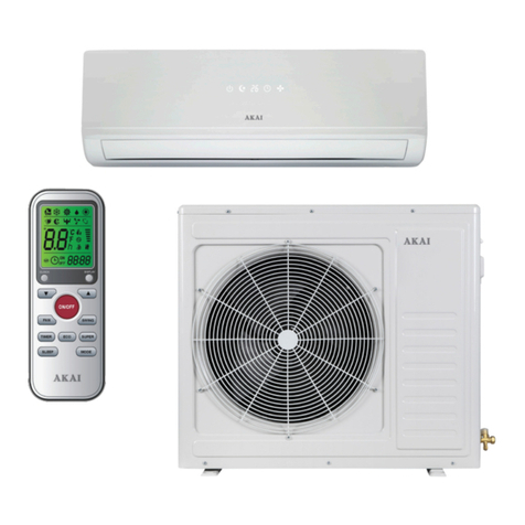
Akai MISTRAL912Dual-R32-K User manual

MODELS:
MISTRAL912Dual-R32-K
(Refrigerant R32)

CONTENT
1. Summary and Features .............................................................................. 1
2. Safety Precautions...................................................................................... 2
3. Specifications.............................................................................................. 4
3.1 Unit Specifications..................................................................................................... 4
3.2 Operation Characteristic Curve ................................................................................ 6
3.3 Capacity Variation Ratio According to Temperature .............................................. 6
3.4 Noise Curve ................................................................................................................ 7
4. Construction Views..................................................................................... 8
4.1 Outdoor Unit ............................................................................................................... 8
5. Refrigerant System Diagram.................................................................... 10
6. Schematic Diagram................................................................................... 10
6.1 Electrical Wiring ....................................................................................................... 10
7. Installation Manual.................................................................................... 12
7.1 Standard Accessory Parts....................................................................................... 12
7.2 Safety operation of ammable refrigerant............................................................ 13
7.3 Installation Location and Matters Needing Attention .......................................... 15
7.4 Test operation.......................................................................................................... 23
8. Exploded Views and Parts List ................................................................ 24
8.1 Outdoor Unit ............................................................................................................. 24
9. Troubleshooting ........................................................................................ 28
9.1 PCB Printed Diagram............................................................................................... 28
10. Removal Procedure ................................................................................ 30
10.1 Removal Procedure of Outdoor Unit(18K)........................................................... 30
10.2 Removal Procedure of Outdoor Unit(24K)........................................................... 36

1
Summary and Features
1. Summary and Features
Outdoor Unit
MISTRAL912Dual-R32-K
SUV3-H24/3CGA-N

2
Safety Precautions
2. Safety Precautions
Installing, starting up, and servicing air conditioner can behazardous due to system pressure, electrical components, and
equipment location, etc.Only trained, qualied installers and service personnel areallowed to install, start-up, and service this
equipment.Untrained personnel can perform basic maintenance fun-ctions such as cleaning coils. All other operations should be
performed by trained service personnel.When handling the equipment, observe precautions in themanual and on tags, stickers,
and labels attached to theequipment. Follow all safety codes. Wear safety glasses andwork gloves. Keep quenching cloth
and re extinguisher nearby when brazing.Read the instructions thoroughly and follow all warnings orcautions in literature and
attached to the unit. Consult localbuilding codes and current editions of national as well as local electrical codes.
Recognize the following safety information:
◆ Make sure the outdoor unit is installed on a stable, level surface with no accumulation of snow, leaves, or trash beside.
◆ Make sure the ceiling/wall is strong enough to bear the weight of the unit.
◆ Make sure the noise of the outdoor unit does not disturb neighbors.
◆ Follow all the installation instructions to minimize the risk of damage from earth quakes, typhoons or strong winds.
◆ Avoid contact between refrigerant and re as it generate spoisonous gas.
◆ Apply specied refrigerant only. Never have it mixed with any other refrigerant. Never have air remain in the refrigerant line as
it may lead to rupture and other hazards.
◆ Make sure no refrigerant gas is leaking out when installation is completed.
◆ Should there be refrigerant leakage, the density of refrigerant in the air shall in no way exceed its limited value, or it may lead
to explosion.
◆ Keep your ngers and clothing away from any moving parts.
◆ Clear the site after installation. Make sure no foreign objects are left in the unit.
◆ Always ensure effective grounding for the unit.
Incorrect handling could result inpersonal injury or death. Incorrect handling may result inminor injury,or damage to product
or property.
Warning Caution
Warning Caution
All electric work must be performed by a licensed technician
according to local regulations and the instructions given in
this manual.
Before installing, modifying, or servicing system,
mainelectrical disconnect switch must be in the OFF position.
There may be more than 1 disconnect switch. Lock out and
tag switch with a suitable warning label.
Never supply power to the unit unless all wiring and tubing
are completed, reconnected and checked.
This system adopts highly dangerous electrical voltage.
Incorrect connection or inadequate grounding can cause
personal injury or death. Stick to the wiring diagram and all
the instructions when wiring.
Have the unit adequately grounded in accordance with local
electrical codes.
Have all wiring connected tightly. Loose connection may lead
to overheating and a possible re hazard.
All installation or repair work shall be performed by your
dealer or a specialized subcontractor as there is the risk of
re, electric shock, explosion or injury.
Never install the unit in a place where a combustible gas
might leak, or it may lead to re or explosion.
Make a proper provision against noise when the unit is
installed at a telecommunication center or hospital.
Provide an electric leak breaker when it is installed in a
watery place.
Never wash the unit with water.
Handle unit transportation with care. The unit should not be
carried by only one person if it is more than 20kg.
Never touch the heat exchanger ns with bare hands.
Never touch the compressor or refrigerant piping without
wearing glove.
Do not have the unit operate without air lter.
Should any emergency occur, stop the unit and disconnect
the power immediately.
Properly insulate any tubing running inside the room to
prevent the water from damaging the wall.

3
Safety Precautions
Please read this operating manual carefully before operating the unit
The gures in this manual may be diffrerent with the material objects, please refer to the material objects for reference .
The Refrigerant
Appliance lled with ammable gas R32.
Before use the appliance,read the ower's manual rst.
Before install the appliance,read the installation manual rst.
To realize the function of the air conditioner unit, a special refrigerant circulates in the system.The used refrigerant is the uoride
R32,which is specially cleaned.The refrigerant is ammable and inodorous. Furthermore,it can leads to explosion under certain
condition.But the ammability of the refrigerant is very low. It can be ignited only by re.
Compared to common refrigerants, R32 is a nonpolluting refrigerant with no harm to the ozonosphere.The inuence upon the
greenhouse effect is also lower. R32 has got very good thermodynamic features which leads to a really high energy efciency.
The units therefore need a less lling.
WARNING:
Do not use means to accelerate the defrosting process or to clean, other than those recommended by the manufacture.Should
repair be necessary, contact your nearest authorized Service Center.
Any repair carried out by unqualied personnel may be dangerous.
The appliance shall be stored in a room without continuously operating ignition sources.
(For example: open ames, an operating gas or an operating electric heater.)
Do not pierce or burn.
Appliance shall be installed, operated and stored in a room with a floor area larger than "X"m2( see table 2).(only applies to
appliances that are not xed applicences).
Appliance lled with ammable gas R32. For repairs, strictly follow manufacturer's instruntions only.
Be aware that refrigerants not contain odour.
Read specialist’s manual.
Before repair the appliance,read the service manual rst.

4
Specifications
3. Specifications
3.1 Unit Specifications
Model -MISTRAL912Dual-R32-K
Product Code -KEJ001W0170
Cooling Capacity KW 5.20
Heating Capacity KW 5.20
EER W/W 3.71
COP W/W 4.16
SEER / 6.10
SCOP(Average) / 4.00
Energy Class / A++/A+
Sound Pressure Level dB(A) 54
Sound Power Level dB(A) 62
Rated Voltage V 220-240
Rated Frequency Hz 50
Phases / 1
Min/Max. Voltage V~ 184/264
Cross-sectional Area of Power Cable Conductor mm21.50
Recommended Power Cable(Core) / 3
Fuse Current A 16
Cooling Power Input KW 1.40
Heating Power Input KW 1.25
Cooling Rated Power Input KW 2.50
Heating Rated Power Input KW 2.25
Cooling Current Input A 6.21
Heating Current Input A 5.55
Cooling Rated Current Input A 11.09
Heating Rated Current Input A 9.98
Compressor Trademark / PANASONIC
Compressor Manufacturer /
PANASONIC WANBAO
APPLIANCES COMPRESSOR
(GUANGZHOU) CO.,LTD.
Compressor Model / 9RD132ZAA21
Compressor Type1 / Inverter Rotary
Compressor Capacity W 3615
Compressor Power Input W 1330
Compressor Rated Load Amp (RLA) A 6.7
Compressor Locked Rotor Amp (L.R.A) A 23
Compressor Thermal Protector / KSD301-11.5/10BC22X2-S4
Compressor Crankcase W 20
Chassis Electrical Heater Power Input W 72
Chassis Electrical Heater Current A 0.32

5
Specifications
Model -SUV2-H18/1CFA-N SUV3-H24/3CGA-N
Fan Type /Axial-ow Axial-ow
Fan Diameter-height mm 522-140 550-124
Fan Diameter-height inch 20.6-5.5 21.6-4.9
Motor Model / SGW60M-ZL SGW120M-ZL
Motor Type /DC motor DC motor
Motor Insulation Class /E E
Motor Safe Class /IP44 IP44
Motor Full Load Amp(FLA) A 1.03 0.96
Fan Motor Type /DC motor DC motor
Fan Motor Speed rpm 750 750
Fan Motor Power Output W 60 120
Fan Motor Power Input W 85 165
Condenser Material / Aluminum Fin-copper Tube Aluminum Fin-copper Tube
Condenser Face Area m20.55 0.73
Condenser Pipe Diameter mm φ7 φ7
Condenser Number of Rows /2 2
Condenser Tube Pitch(a)×Row Pitch(b) mm 22×19.05 22×19.05
Condenser Fin Pitch mm 1.4 1.4
Condenser Length(L) × Height(H) × Width(W) mm 875×660×38.1 970×748×38.1
Permissible Excessive Operating Pressure for the
Discharge Side MPa 4.3 4.3
Permissible Excessive Operating Pressure for the
Suction Side MPa 2.5 2.5
Cooling Operation Ambient Temperature Range ℃-15~55 -15~55
Heating Operation Ambient Temperature Range ℃-20 ~30 -20~30
Maximum drive IDU NO. unit 2 3
Defrosting Method /Automatic Defrosting Automatic Defrosting
Isolation /I I
Moisture Protection /IP24 IP24
Overload Protector // /
Climate Type /T1 T1
Refrigerant /R32 R32
Refrigerant Charge kg 1.10 1.50
Throttling Method / Electron expansion valve Electron expansion valve
Dimension of Outline(W) mm 960 990
Dimension of Outline(D) mm 396 426
Dimension of Outline(H) mm 700 790
Connection Pipe Max. Height Distance
(indoor and indoor) m 5 5
Max. equivalent connection pipe length
(outdoor to last indoor) m 10 20
Connection Pipe Max. Length Distance
(total lenght) m 20 60

6
Specifications
3.2 Operation Characteristic Curve
Compressor Speed(rps)
Cooling
Heating
Current(A)
Current(A)
0
1
2
3
4
5
6
7
8
9
10
020406080 100 120
WB19
°C
0
1
2
3
4
5
6
7
8
020406080100
12
0
Condition
Indoor:DB 27°C
Indoor air flow: Super High
Pipe length:5m
Voltage:230V
Condition
Indoor:DB 20°C
Indoor air flow: Super High
Pipe length:5m
Voltage:230V
3.3 Capacity Variation Ratio According to Temperature
50
60
70
80
90
100
110
120
130
32 33 34 35 36 37 38 39 40 41 42 43 44 45 46
Capacity ratio(%)
Outdoor temp. (°C)
Capacity ratio(%)
HeatingCooling
HeatingCooling
-20 -15-10 -5 0510
110
120
130
100
90
80
70
60
50
40
Outdoor temp.(°C)
50
60
70
80
90
100
110
120
130
32 33 34 35 36 37 38 39 40 41 42 43 44 45 46
Capacity ratio(%)
Outdoor temp. (°C)
Capacity ratio(
%)
–15–10 –5
110
100
90
80
70
60
50
40
05
710
Conditions
Indoor:DB20°C
Indoor air flow:Super High
Pipe length:5m
Outdoor temp.(°C)
Condition
Indoor:DB27°C WB19°C
Indoor air flow:
High
Pipe length:5m
Condition
Indoor:DB27°C WB19°C
Indoor air flow:
High
Pipe length:5m
Condition
Indoor:DB20°C
Indoor air flow:
High
Pipe length:5m
Heating operation ambient temperature range is -20ºC~24ºC
Heating operation ambient temperature range is -15ºC~24ºC

7
Specifications
3.4 Noise Curve
Indoor side noise when blowing
Outdoor side noise when blowing
Indoor fan motor rotating speed
Compressor frequency(Hz)
Noise/dB(A)
50
60
30
40
20
Low Middle High Super High
12K
09K
46
48
50
52
54
56
58
60
62
20 03045060708
09
0
Noise dB(A)
18K
24K

8
Construction Views
4. Construction Views
4.1 Outdoor Unit
Unit:mm
890
960
700
368
340
396
560
MISTRAL912Dual-R32-K

9
Construction Views
SUV3-H24/3CGA-N
Unit:mm
920
990
790
394
370
426
610

10
Refrigerant System Diagram
5. Refrigerant System Diagram
6. Schematic Diagram
6.1 Electrical Wiring
Symbol OG WH YE RD YEGN BN BU BK VT
Color symbol ORANGE WHITE YELLOW RED YELLOW GREEN BROWN BLUE BLACK VIOLET
Symbol COMP CT1,2 4V XT
Parts name COMPRESSOR OVERLOAD 4-WAY VALVE TERMINAL BLOCK PROTECTIVE EARTH
Meaning of marks
The outdoor and indoor units start to work once the power is switched on. During the cooling operation, the low
temperature, low pressure refrigerant gas from the heat exchanger of each indoor unit gets together and then is
taken into the compressor to be compressed into high temperature, high pressure gas, which will soon go to the heat
exchanger of the outdoor unit to exchange heat with the outdoor air and then is turned into refrigerant liquid. After
passing through the throttling device, the temperature and pressure of the refrigerant liquid will further decrease and then
go the main valve. After that, it will be divided and go to the heat exchanger of each indoor unit to exchange heat with the
air which needs to be conditioned. Consequently, the refrigerant liquid become low temperature, low pressure refrigerant
gas again. Such a refrigerant cycle goes round and round to achieve the desired cooling purpose. During the heating
operation, the four-way valve is involved to make the refrigerant cycle reversely. The refrigerant radiates heat in the heat
exchanger of the indoor unit(so do the electric heating devices)and absorb heat in the heat exchanger of the outdoor unit
for a heat pump heating cycle so as to achieve the desired heating purpose.
D
c
S
E
Gas/Liquid Separator
Compressor
Four-Way Valve
Motor
Capillary
Electronic Expansion Valve
Heat Exchanger
2#
Heat Exchanger
Filter
1#
3#

11
Schematic Diagram
MISTRAL912Dual-R32-K
SUV3-H24/3CGA-N
These circuit diagrams are subject to change without notice, please refer to the one supplied with the unit.

12
Installation Manual
7. Installation Instructions
7.1 Standard Accessory Parts
The standard accessory parts listed below are furnished and should be used as required.
Name Appearance Q’ty Usage
Drainage
Connecter 1To connect with the hard PVC
drain pipe
Drain Plug 3 To plug the unused drain hole
Pipe Joint
Subassembly 1 or 2
One for 18K unit,
Two for 24K unit,
Others Instructions , bar code
Table 1
Table 1
90mm
Joined with the pipe
joint of outdoor Unit
Joined with the connection pipe
connected with indoor Unit
NO. Joined with the connection pipe
connected with indoor Unit
Joined with the pipe
joint of outdoor Unit Usage
1Φ12.7 Φ9.52 one for 18K unit,
two for 24K unit,
Pipe Joint Subassembly

13
Installation Manual
7.2 Safety operation of ammable refrigerant
Qualification requirement for installation and maintenance man
Installation notes
Maintnance notes
Welding
Filling the refrigerant
Safety instructions for transportation and storage
Table 2: Minimum room area (m2)
All the work men who are engaging in the refrigeration system should bear thevalid certication awarded by the authoritative
organization and the qualication for dealing with the refrigeration system recognized by this industry. If it needs other technician
to maintain and repair the appliance, they should be supervised by the person who bears the qualication for using the ammable
refrigerant. It can only be repaired by the methood suggested by the equipment's manufacturer.
1.The air conditioner is not allowed to use in a room that has running re(such as resource, working coal gas ware, operating
heater).
2.It is not allowed to drill hole or burn the connection pipe.
3.The air conditioner must be installed in a room that is larger than the minimum roomarea. The minimum room area is shown on
the nameplate or following table 2.
4.Leak test is a must after installation.
If you should cut or weld the refrigerant system pipes in the process of maintaining, please follow the steps as below:
1.Shut down the unit and cut power supply.
2.Eliminate the refrigerant.
3.Vacuuming.
4.Clean it with N2 gas.
5.Cutting or welding.
6.Carry back to the service spot for welding.
The refrigerant should be recycled into the specialized storage tank. Make sure that there isn't any naked ame near the outlet
of the vacuum pump and it's well-ventilated.
1.Use the refrigerant lling appliances specialized for R32. Make sure that different kinds of refrigerant won't contaminate with
each other.
2.The refrigerant tank should be kept upright at the time of lling refrigerant.
3.Stick the label on the system after lling is nished(or haven't nished).
4.Don't overlling.
5.After lling is nished, please do the leakage detection before test running;another time of leak dection should be done when it
is removed.
1.Please use the ammable gas detector to check before unload and open the container .
2.No re source and smoking.
3.According to the local rules and laws.
Check whether the maintenance area or the room area meet the requirement of the nameplate.
—It’s only allowed to be operated in the rooms that meet the requirement of the nameplate.
Check whether the maintenance area is well-ventilated.
—The continuous ventilation status should be kept during the operation process.
Check whether there is fire source or potential fire source in the maintenance area.
—The naked ame is prohibited in the maintenance area; and the "no smoking" warning should be hanged.
Check whether the appliance mark is in good condition.
—Replace the vague or damaged warning mark.
Minimum
room area
(m2)
Charge amount (kg) ≤1.2 1.3 1.4 1.5 1.6 1.7 1.8 1.9 2.0 2.1 2.2 2.3 2.4 2.5
Floor location / 14.5 16.8 19.3 22.0 24.8 27.8 31.0 34.4 37.8 41.5 45.4 49.4 53.6
Window mounted / 5.2 6.1 7.0 7.9 8.9 10.0 11.2 12.4 13.6 15.0 16.3 17.8 19.3
Wall mounted / 1.6 1.9 2.1 2.4 2.8 3.1 3.4 3.8 4.2 4.6 5.0 5.5 6.0
Ceiling mounted / 1.1 1.3 1.4 1.6 1.8 2.1 2.3 2.6 2.8 3.1 3.4 3.7 4.0

14
Installation Manual
Installation prepare
Notice for installion
Please notice that the unit is lled with ammable gas R32. Inappropriate treatment of the unit involves
the risk of severe damages of people and material. Details to this refrigerant are found in chapter
"refrigerant".
To ensure the safety, please be mindful of the following precautions
1. When installing or relocating the unit, be sure to keep the refrigerant circuit free from air or substances other than the
specified refrigerant.
— Any presence of air or other foreign substance in the refrigerant circuit will cause system pressure rise or compressor rupture,
resulting in injury.
2. When installing or moving this unit, do not charge the refrigerant which is not comply with that on the nameplate or
unqualified refrigerant.
— Otherwise, it may cause abnormal operation, wrong action, mechanical malfunction or even series safety accident.
3. When refrigerant needs to be recovered during relocating or repairing the unit, be sure that the unit is running in
cooling mode.Then, fully close the valve at high pressure side (liquid valve). About 30-40 seconds later,fully close
the valve at low pressure side(gas valve), immediately stop the unit and disconnect power. Please note that the time
for refrigerant recovery should not exceed 1 minute.
— If refrigerant recovery takes too much time, air may be sucked in and cause pressure rise or compressor rupture, resulting in
injury.
4. During refrigerant recovery, make sure that liquid valve and gas valve are fully closed and power is disconnected
before detaching the connection pipe.
— If compressor starts running when stop valve is open and connection pipe is not yet connected, air will be sucked in and cause
pressure rise or compressor rupture, resulting in injury.
5. When installing the unit, make sure that connection pipe is securely connected before the compressor starts running.
— If compressor starts running when stop valve is open and connection pipe is not yet connected, air will be sucked in and cause
pressure rise or compressor rupture, resulting in injury.
6. Prohibit installing the unit at the place where there may be leaked corrosive gas or ammable gas.
— If there leaked gas around the unit, it may cause explosion and other accidents.
7. Do not use extension cords for electrical connections. If the electric wire is not long enough, please contact a local
service center authorized and ask for a proper electric wire.
— Poor connections may lead to electric shock or re.
8. Use the specified types of wires for electrical connections between the indoor and outdoor units. Firmly clamp the
wires so that their terminals receive no external stresses.
— Electric wires with insufcient capacity, wrong wire connections and insecure wire terminals may cause electric shock or re.
WARNING
1. The unit should be installed only by authorized service center according to local or government regulations and in compliance
with this manual.
2. Before installing, please contact with local authorized maintenance center. If the unit is not installed by the authorized service
center, the malfunction may not be solved due to incovenient contact between the user and the service personnel.
3. When removing the unit to the other place, please rstly contact with the local authorized service center.
4. Warning: Before obtaining access to terminals, all supply circuits must be disconnected.
5. For appliances with type Y attachment, the instructions shall contain the substance of the following. If the supply cord is
damaged, it must be replaced by the manufacturer, its service agent or similarly qualied persons in order to avoid a hazard.
6. The appliance must be positioned so that the plug is accessible.
7. The temperature of refrigerant line will be high; please keep the interconnection cable away from the copper tube.
8. The instructions shall state the substance of the following:This appliance is not intended for use by persons(including children)
with reduced physical, sensory or mental capabilities, or lack of experience and knowledge, unless they have been given
supervision or instruction concerning use of the appliance by a person responsible for their safety. Children should be
supervised to ensure that they do not play with the appliance.
9. Appliance shall be installed, operated and stored in a room with a oor area larger than "X" m2(see table 2).
Caution

15
Installation Manual
7.3 Installation Location and Matters Needing Attention
The installation of the unit must comply with the national and local safety regulations. The installation quality directly affects
the normal use, so the user should not carry out the installation personally, instead, the installation and debugging should be
done by technician according to this manual. Only after that, can the unit be energized.
● How to select the installation location for the outdoor unit
1. The outdoor unit must be installed where the bearing surface is stable and secure enough.
2. The outdoor unit and indoor unit should be placed as close as possible to minimize the length and bends of the refrigerant
pipe.
3. Do not install the outdoor unit under the window or between the buildings to prevent the normal running noise entering the
room.
4. Where the ow of the air inlet/outlet is not blocked.
5. The outside unit should be installed where ventilation is in good condition so that the unit can take in and discharge
enough air.
6. Do not install the unit where there are inammable and explosive substances and where there is heavy dust、salt fog and
other severely polluted air.
No air guiding pipe is allowed to be installed at the air inlet/outlet of the outdoor unit.
Under the heating mode, the condensate water would drip down from the base frame and would be frozen when the outdoor
ambient temperature is lower than 0°C (32°F). Besides, the installation of the outdoor unit should not affect the heat radiation
of the unit.
The unit installed in the following places is likely to run abnormally. If unavoidable, please contact the professional personnel
at the appointed service center.
● Where is full of oil.
● Alkaline soil off the sea.
● Where there is sulfur gas (like sulfur hot spring).
● Where there are devices with high frequency (like wireless devices, electric welding devices, or medical equipment).
● Special circumstances.
CAUTION!
● Electric wiring
1. The installation must be done in accordance with the national wiring regulations.
2. Only the power cord with the rated voltage and exclusive circuit for the air conditioning can be used.
3. Do not pull power cord by force.
4. The electric installation should be carried out by the professional personnel as instructed by the local laws, regulations
and also this manual.
5. The diameter of the power cord should be large enough and once it is damaged it must be replaced by dedicated one.
6. The earthing should be reliable and the earth wire should be connected to the dedicated device of the building by the
professional personnel. Besides, the air switch coupled with the leakage current protection switch must be equipped,
which is of enough capacity and of both magnetic and thermal tripping functions in case of the short circuit and overload.
Models Power Supply Capacity of the
Air Switch
Recommended Cord
(pieces×sectional area)
MISTRAL912Dual-R32-K 220-240V~,50Hz 16A 3×1.5mm2
SUV3-H24/3CGA-N 220-240V~,50Hz 25A 3×2.5mm2
Table 3

16
Installation Manual
Notes:
1. The specications of the breaker and power cable listed in the table above are determined based on the maximum
power (maximum amps) of the unit.
2. The specications of the power cable listed in the table above are applied to the
conduit-guarded multi-wire copper
cable (like, YJV copper cable, consisting of PE insulated
wires and a PVC cable jacket) used at 40°C and resistible to
90°C (see IEC 60364-5-562). If the working condition changes, they should be modied according to the related
national standard.
3. The specications of the breaker listed in the table above are applied to the breaker with the working temperature at
40°C. If the working condition changes, they should be modied according to the related national standard.
● Noise precautions
1. The air conditioning unit should be installed where ventilation is in good condition,otherwise the working capability of
the unit would be reduced or working noise would be increased.
2. The air conditioning unit should be installed on the base frame which is stable and secure uncouth to withstand the
weight of the unit, otherwise it would incur vibration and noise.
3. During the installation, a consideration should be taken that the produced hot air or noise should not affect neighbors
or surroundings.
4. Do not stack obstacles near the air outlet of the outdoor unit, otherwise it would reduce the working capability of the
unit or increase the working noise.
5. In the event of the occurrence of abnormal noise, please contact the sales agent as soon as possible.
6. Accessories for installation
Refer to the packing list for the accessories of the indoor and outdoor units respectively.
● Precautions for the installation of the outdoor unit
The following rules should be followed when the installation location is being considered so as to let the unit run well
enough.
1. The discharged air from the outdoor unit won’t return back and enough space should be left for maintenance around
the unit.
2. The installation location should be in good condition so that the unit is able to take in and discharge enough air.
Besides, make sure there is no obstacle at the air inlet/outlet of the unit. If there is, remove it.
3. The unit must be installed where it is secure enough to support the weight of the unit and capable of reducing to some
extent noise and vibration to make sure they do not bother your neighbors.
4. The designated lifting hole must be used for lifting the unit and protect the unit carefully during lifting to prevent
damaging the mental sheet which would result in rusting in future.
5. The unit should be installed where there is as little as direct sunlight.
6. The unit must be installed where the rain water and defrosting water can be drained.
7. The unit must be installed where the unit won’t be covered by the snow and won’t be affected by rubbish and oil fog.
8. Rubber or spring shock absorbers should be used during the installation of the outdoor unit to meet the noise and
vibration requirements.
9. The installation dimensions should meet the requirement covered in this manual and the outdoor unit must be xed
securely.
10. The installation should be carried out by the professionally skilled personnel.
Installation of the Outdoor Unit
● Earthing Requirements
1. The air conditioner is classied into the class l appliances, so its earthing must be reliable.
2. The yellow-green line of the air conditioner is the earth line and cannot be used for other purpose, cut off or xed by
the tapping screw, otherwise it would cause the hazard of the electric shock.
3. The reliable earth terminal should be provided and the earth wire cannot be connected to any of the following places.
(1) Running water pipe
(2) Coal gas pipe
(3) Sewage pipe
(4) Other places where the professional personnel think unreliable.

17
Installation Manual
● Installation of the Outdoor Unit
1. During the transportation of the outdoor unit, two lifting ropes long enough must be used in four directions and the
separation included angle must be less than 40° prevent the center of unit deviating.
2. During the installation, M10 screws should be used to x the support leg and base frame of the unit.
3. The unit should be installed on a concrete base frame with a height of 10cm.
4. The installation space of the unit should be as required in Fig.1.
Fig.1
>500
>500
>500
>500
>2000
>2000
>1000
Connection between Indoor and Outdoor Units
● Energy level and Capacity Code of the Indoor and Outdoor Units
Energy Level Capacity Code
Indoor Unit
07 23
09 26
12 35
18 52
Outdoor Unit 18 52
24 71
Table 4
Installation Space Requirements of the Outdoor Unit:
Units: mm
1. The outdoor unit with energy level 18 can drive up to two sets of indoor units, the outdoor unit 24 can drive up to three.
2. The sum of the capacity codes of the indoor units should be among 50%-150% of that of the outdoor unit.
● Wiring of the Power Cord
A breaker must be installed, capable of cutting off the power supply for the whole system.
1. Remove the handle(front board) of the outdoor.
2. Remove the wire clip; connect the power connection wire and signal control wire (only for cooling and heating unit) to
the wiring terminal according to the color,x them with screws.
3. Fix the power connection wire and signal control wire with wire clip (only for cooling and heating unit).
4. Reinstall the handle(front board).
CAUTION!

18
Installation Manual
OUTDOOR UNIT
NL 23N(1)
XT XT1
POWER
XT2
INDOOR UNIT 1
BU BK BN YEGN
PE PE
BU BN YEGN
23N(1)
INDOOR UNIT 2
BU BK BN YEGN
MISTRAL912Dual-R32-K
OUTDOOR UNIT
NL
XT
POWER
BU BN YEGN
23N(1)
XT1
INDOOR UNIT 1
BU BK BN YEGN
PE XT2 PE
23N(1)
INDOOR UNIT 2
BU BK BN YEGN
XT3 PE
23N(1)
INDOOR UNIT 3
BU BK BN YEGN
SUV3-H24/3CGA-N
● Allowable Length and Height Fall of the Refrigerant Pipe
Table 5
Allowable Length Refrigerant Pipe
18K 24K 18K 24K
Totlal Length(m) 30 60 L1+L2 L1+L2+L3
Max. Length for Single
Unit(m) 15 20 LX
Max.
installation
altitude
Outdoor unit
and indoor unit 5 10 H1
Indoor unit and
indoor unit 5 5 H2
This manual suits for next models
2
Table of contents
Other Akai Air Conditioner manuals

Akai
Akai AUS-12H53R150P9 User manual

Akai
Akai AK-9000WIFI User manual

Akai
Akai AK-T35R32 User manual

Akai
Akai AK-9000-RC User manual

Akai
Akai AUS-12H53R150P9 User manual

Akai
Akai TAK-9000-25 User manual

Akai
Akai AK-9000-RC User manual

Akai
Akai AK-9000WIFI User manual

Akai
Akai AK-T70R32 User manual

Akai
Akai MWF-18CRN1-QC1G User manual
Popular Air Conditioner manuals by other brands

Lennox
Lennox FLEXY FX 025 Application guide

Sharp
Sharp CVP12PX - Ha Sh 11500 Btu Portable Air... Installation and operation manual

Gree
Gree Neo COZY9K owner's manual

Mitsubishi Electric
Mitsubishi Electric City Multi Series Technical & service manual

Frigidaire
Frigidaire FFMS121CQ10 installation manual

LG
LG LS243HLV3 Engineering manual