Akcome SK6 Series User manual

01
安全与操作说明
Safety Warning and Operation Notice
1
电池组件暴露在阳光下能产生电流。单个组件的电压小于50 VDC,但当组件串联起来时整个电压极高。
为了防 止电弧作用,着火及触电的危险,以下内容应被充分理解、遵守。
PV modules can generate electricity upon exposure to light. The voltage of a single module is less than 50
VDC, but the total voltage can be dangerously high when modules are connected together in series. The following
must be fully understood and obeyed when handling the PV modules to avoid risk of arcing, fire and electric
shock.
在安装、使用和保养光伏系统之前请仔细阅读安装使用手册,并且遵守本手册中的安全防范措施,否则有可能引起
人身财产损失。
Carefully read through these installation instructions before installing, operating or maintaining PV system. Failure to
follow these instructions may result in bodily injury or damage to property.
光伏系统产生的高电压和强电流可能会造成严重的伤害和生命危险。
PV systems can produce high voltage and current which could cause serious injury or even death.
安装组件系统需要有专业技能和知识,并且只能由具有资格认证或被授权的人来进行操作。
The installation of PV modules should only be performed by qualified personnel.
安装时不能穿戴金属首饰。不要赤手接触带电接线端子。选择绝缘的工具进行电气连接。
Do not wear metallic jewelry when installing. Do not touch live terminals with bare hands. Use insulated tools for electri-
cal connections。
不要在潮湿的条件下安装组件。
Do not install PV modules at wet conditions.
破损的组件应放弃使用。损坏的组件应被覆盖遮光以免暴露在阳光下,产生导电的危险。
Do not use damaged nor defective modules. Even damage or defective modules can produce electricity. Keep
damaged or defective modules covered to avoid exposure to light.
无论组件有没有连接,接触组件接线端等导电部分都可能引起电火花或者电击。
Contact with electrically active parts of a PV module such as terminals, can result in burns sparks and lethal shock
whenever the PV modules are connected or not.
接线时使用正确的安全劳保用品和工具设备。
Use appropriate safety equipments when working on any wiring.
DANGER OF DEATH FROM ELECTRICAL SHOCK!
小心触电!

01
安全与操作说明
Safety Warning and Operation Notice
2
DANGER OF DEATH FROM ARCING!
电弧危险!
1.1 安全规范 General Safety
不要拆卸或破坏包括铭牌在内的光伏组件上的任何部件。
Never disassemble nor break any part of the PV module, including nameplate.
确保光伏系统周围没有孩童和其他未经授权人员。
Keep children and other unqualified people away from the PV system.
当组件串或组件串中的组件连接分离时,可能产生致命性电弧。操作应由配备专业工具的专业人员进行。
PV modules generate current under sunlight. A lethally strong arc may occur when breaking a connected module or a
string of modules. Operation should be performed only by professional engineers equipped with professional tools.
当逆变器连接在主干网时,禁止将太阳能组件从逆变器断开,应先将在逆变器上的保险丝从交流侧移开。
Never disconnect the PV module from the inverter when the inverter is still connected to the main grid, but remove the
fuse from the AC side on the inverter before operation.
保证电缆以及连接器连接在最佳状态。(防止裂开,腐蚀或者污染)
Ensure cable and connectors are at perfect condition (no splitting, soiling, nor contamination).
在没有使用个人防护装置或者佩戴绝缘手套的时候,一定不能触碰潮湿的连接器。
One should never touch the wet connectors, without using personal protective equipments or wearing insulating gloves.
所有的光伏电池组件的安装,都应当遵守安装所在地一切适用的法律法规、标准条例。
All PV modules installation should be in accordance with applicable international and related local laws, codes and
regulations.
人造日光不可集中在组件上。不可将组件用镜子,透镜及其他类似材料将阳光投射在光伏组件上。
Artificial sunlight should not be concentrated upon the PV modules. Do not expose PV modules to sunlight concentrat-
ed with mirrors, lens or other means.

01
安全与操作说明
Safety Warning and Operation Notice
3
1.2 操作安全 Handling Safety
在正常条件下,光伏组件有可能产生比标准测试条件下所得标称值更高的电压和电流。相应地,在确定光伏系统其
他部件的电气参数时,应至少乘以1.25倍的安全系数。
Under normal conditions, a photovoltaic module is likely to experience conditions that produce more current and/or
voltage than reported at standard test conditions. Accordingly, the values of Isc and Voc marked on this module should
be multiplied by a factor of 1.25 when determining component voltage ratings, conductor ampacities, fuse sizes, and
size of controls connected to the PV output.
只有同一类型的光伏组件才能被串联在一起。
Only PV modules with the same cell type and size may be connected in series.
避免光伏组件上的阴影。阴影部分的组件变热(热斑现象)将会对组件造成永久损伤甚至引发火灾。
Avoid any shade on the PV module surface. Shaded cells may become hot (hotspot phenomenon) resulting in perma-
nent damage to the module or even fire hazard.
请遵守光伏系统中使用的其他部件的安全保护措施的要求。
Follow safety precautions of all other components used in the PV system.
请遵循拆箱说明进行拆包。一片组件的搬运应至少由两名人员共同实施。不要随意搁置、堆放拆包后的光伏组件,
并保证没有物体压或落在光伏组件上。
Follow the unpacking instruction. Carry the module by at least two persons. Do not lay nor pile the PV module casually.
Avoid any objects stacking or falling on the PV modules.
玻璃易滑,禁止在组件上踩踏,防止受伤及玻璃损坏导致的电击。
Do not stand nor step on the PV module. The glass may be slippery, and there is a risk of injury or electric shock if glass
is broken.
组件在安装搬运等过程中应注意轻拿轻放, 避免任何的磕碰或掉落。
Please handle PV modules with care, avoiding any bump or drop.
禁止对组件施加过大的压力或扭力,否则将会损坏边框、玻璃或者里面的太阳能电池。
Do not expose the PV module to excessive loads on the surface of the PV module nor twist the frame, otherwise, the
glass and solar cells may break.
安装中切勿用力拉扯接线盒线缆,连接后的线缆宜处于松弛状态。
Do not draw the cable of J-box excessively during installation. The cables should be in a relaxed state after connection.
组件边缘锐利,请不要裸手接触电池组件以免造成伤害。应带上手掌和手指处设有填充物的防护手套。
Do not touch the PV module with bare hands. The frame of the PV module has sharp edges and may cause injury.
Wear suitable gloves, such as leather gloves with padding in the palm and finger areas.

01
安全与操作说明
Safety Warning and Operation Notice
4
1.4 防火安全 Fire Safety
戴上保护性头盔,绝缘手套以及安全鞋(有橡胶底)。
Always wear protective helmet, insulating gloves and safety shoes (with rubber soles).
为了防止电击的危险,请不要再电池组件潮湿的状态下进行操作。
Due to risk of electrical shock, never perform work when PV modules are wet.
请不要在雨雪或大风天气下进行组件的安装。
Do not install PV modules at rainy, snowy or windy conditions.
保证连接器充分、正确地插接不松脱。所有的连接器、线缆应安全的固定在组件边框、支架结构上或线缆管道中,
以防止移动。避免连接器直接阳光照射或水浸没。
Ensure the connectors are fully and correctly connected. Connectors and cables should be fixed to the PV module
frames, support structure or raceway to prevent movement. Keep connectors out of direct sunlight or water immer-
sion.
安装时,无论组件有没有接入系统,不能裸手接触电缆一端及接线盒。
Do not touch the J-box and the end of the cables with bare hands during installation, regardless of whether the PV
module is connected to the system or not.
当系统电路接入工作负荷中时,不要拔掉连接器。
Do not unplug connectors if the system circuit has been connected to an operating load.
当进行屋顶或其他结构安装时,应全程使用恰当的安全措施或者设备以防止伤害。
When installing PV modules on roofs or other structures, appropriate safety practices and safety equipments should
be used at all times to avoid injury.
组件应用安全等级为Class II,可用于>直流50V 或240W以上的系统。
The Safety Class of Solar module is Class II, which can be used in systems operating at greater than 50 V DC or
240 W, where general contact access is anticipated.
光伏组件不可被安装在易燃易爆气体、有害化学品、火源附近。
The PV modules should never be installed near inflammable gas, hazardous chemicals or fire source.
爱康光伏组件防火等级为A级(除非特殊说明)。对于屋顶光伏系统,应将组件安装在防火屋顶上。
The PV modules have been rated as Fire Class A (unless specified). For roof PV project, the PV modules are to be
mounted over a fire resistant roof.
光伏系统应包含防雷装置。
There should be lightening protection devices in the PV system.
1.3 安装安全 Installation Safety

02
组件安装
Mounting Instruction
5
2.2 安装规范 General Installation
不要将组件安装在有可能会被水淹没或浸没的地方。
Do not install the PV module where could be flooded or immerged.
不要将组件置于有易燃气体的环境中(例如加油站,储气罐等装置),也不要靠近火源。
Do not install the PV module in a flammable gas environment (such as gas station, storage tank etc.) nor near fire
source.
组件能工作的极限环境温度范围为-40℃到85℃。推荐组件安装所在地的环境温度范围为-20℃到40℃。
Temperature endurance range of the PV module is -40℃ ~ 85℃ , while the environmental temperature range of -20
℃ ~ 40℃ is recommended for module installation.
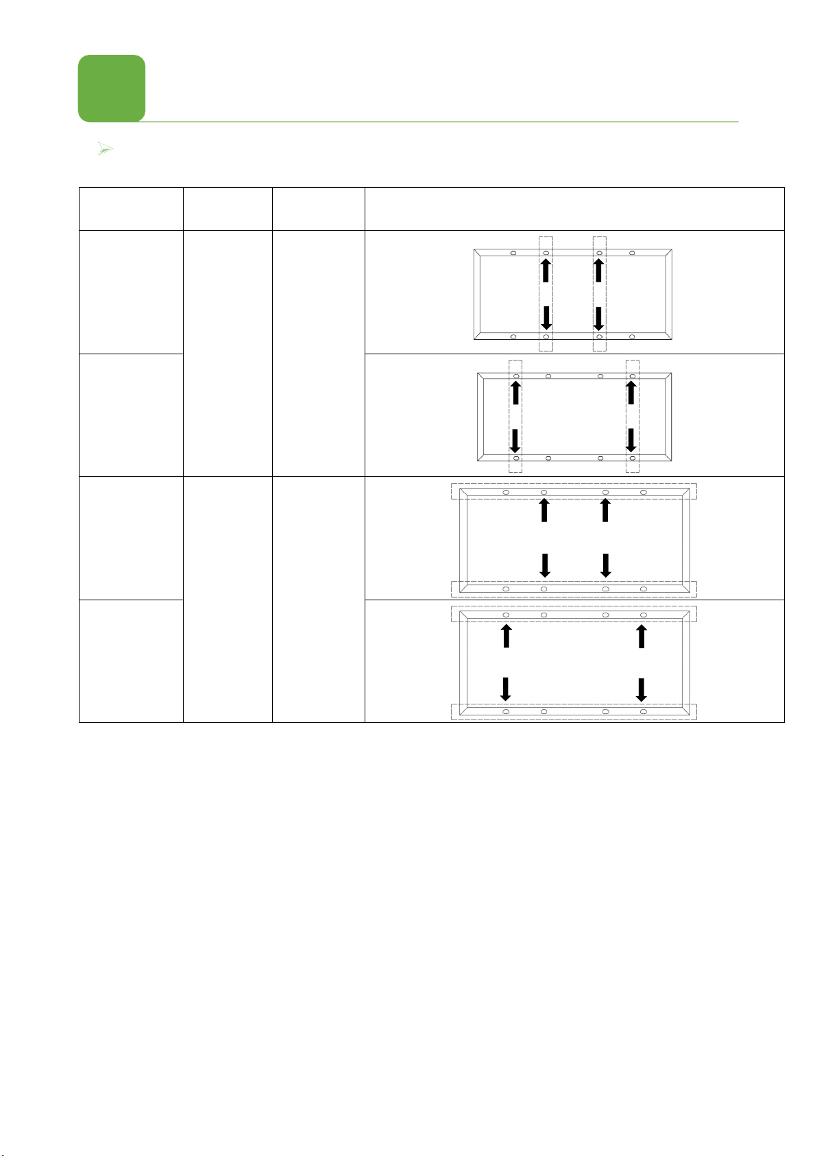
除非特殊说明,组件的正面最大承载不能超出5400Pa,反面最大承载2400Pa。需充分考虑安装环境的风压、雪
压。如遇长时间积雪,应及时清理组件表面以防止对组件造成损害。
Unless specified, the maximum bearing load of PV module is 5400Pa for front side, and 2400Pa for backside. The
natural environment condition should be fully considered to not to exceed the maximum pressure. The accumulated
snow should be removed in time to prevent causing any damage to the PV modules.
光伏组件不能在过量盐雾、冰雹、风沙、烟尘、空气污染、活跃的化学气氛、酸雨等环境中安装和使用。
The PV module should not be installed in the environment of excessive salt fog, hail, sand and dust,, smoke, active
chemical atmosphere, acid rain etc.
光伏组件应安装在距离海边至少200m之外。 距离海岸200m~1000m之间的安装,应特别采用相应的措施避免组
件腐蚀和接地失效。建议在距离海岸1000米之外安装。
The PV module should be installed at least 200m away from the sea side. Corresponding measure should be adopted
to avoid module corrosion and grounding failure for the distance of 200m~1000m away from sea side. Installation of
1km away from sea side is recommended.
组件安装前,应充分评估安装场地、环境的状况,确认适合光伏系统安装。光伏系统安装的设计须由专业人员完
成,符合所有相关建筑和电气规范,并从相关部门获得施工许可。
Condition of site should be fully investigated to ensure it is suitable for PV system. The installation should be designed
by qualified engineer, conforming to all relevant construction/electrical laws, regulations and codes. PV installation
should be approved by relevant authorities.
光伏组件应安装在支架之上。系统的其他部件,不应对组件产生机械或电气方面的破坏性影响。
The PV module should be mounted on supporting structures. Other components of the PV system should not have any
undesirable mechanical or electrical influence on the PV module.
2.1 选址与环境 LocationSelection and Environment

02
组件安装
Mounting Instruction
6
支架结构承载能力应足够,包括组件重量和其承受的风压,雪压,以及安装过程中承受的人员和设备重量。支架设计要保证在热
涨的情况下不会影响到组件。
Bearing ability of the supporting structure should be enough to sustain the modules weight and wind/snow pressure,
as well as the pressure from installers and apparatus. Design of supporting structure should guarantee that there will
be no affect on the modules when hot swell happens.
光伏组件可采用螺栓或夹具压块牢固固定在支架上。组件间应留有至少10mm间隙。
The PV module should be firmly fixed with bolts or clamps on the supporting structure. The interval between modules
should be at least 10mm.
在安装光伏组件时不要破坏组件的任何部件,不要在边框上钻孔,否则将取消保修。
Do not cause any damage of the PV modules during mounting. Do not drill holes on the frame. Otherwise, the
warranty is not valid any more.
接线盒导线的弯曲半径不能小于60mm。
Bending radius of the J-box cable should be more than 60mm.
光伏系统所在环境应保持良好的通风以利于组件的散热,利于提升组件发电量和降低火灾隐患。
Module installation site should maintain good ventilation to facilitate the heat dispassion, which is in favor of the power
generation and fire safety.
对于地面电站,组件下沿应至少离地一米防止泥土杂草或冰雪覆盖组件。
For PV installation on the ground, the modules are expected to be at least one meter high from the ground to avoid
soil , grass and snow covering the bottom part of the modules.
对于屋顶电站,屋顶的设计结构和承重必须适合光伏系统的安装。应保证安装的牢固以防止组件从无屋顶滑落。组件背面和屋面
应至少留有20厘米间距。
For PV installation on the rooftop, the structure and bearing ability of roof must be suitable. The fastness of installa-
tion should be guaranteed to avoid the module falling off from rooftop. There should be a gap of at least 20cm
between the module and roof.
CAUTION!
注意!
屋顶结构会影响防火所以故障断路器,保险丝,短路开关逗应尽量安装在地面上。否则将造
成不必要的损伤!
Roof structure will effect the fireproofing so it’s necessary to earth ground fault
circuit breaker. Unsuitable installation will bring on exrta damages!
在无风的天气下屋顶上安装组件,强风下可能会造成事故。
When installing the module on a roof or building, do so in calm winds. Installing a
module during strong winds may cause accidents!
对于需要将组件安装在水面上的系统项目,系统安装商必须提前提出详细的安装要求。以便组件制造厂选用合适的材料搭配适应
水面安装条件。
For the project on water surface, installation conditions should be provided in advance, so that the module manufac-
turer can choose the suitable materials to be in accord with the water surface installation conditions.

02
组件安装
Mounting Instruction
7
本安装手册提及的组件适用于海拔2000米以下安装使用,载荷能力均为设计载荷,其安全因子为1.5。
The modules mentioned in this installation manual are only allowed to be installed below 2000 m above sea
level.The load capacity of the module is design load, and its safety factor is 1.5.
光伏组件有两种方式安装在支架结构上:图例A压块夹紧式;图例B背面螺栓固定式。安装时使用扭力扳手,拧紧力矩应在15-
20Nm之间。
PV modules can be mounted to the substructure by screwing (Example A) at the back side. Torque wrench is
recommended for installation. The tightening torque should be 15-20Nm.
例子 A:压块夹紧式
Example A: Clamping
例子 B:螺栓固定式
Example B: Bolting
1)不锈钢锁紧螺母 Stainless steel lock nut
2)不锈钢垫片 Stainless steel washer
3)不锈钢M8螺栓Stainless steel M8 bolt
安装方式A:压块安装
Installation method A: Mounting with Clamps
注:测试载荷= γm(安全因子) × 设计载荷,γm=1.5;;a≥5cm
Note: Test load = γm(safety factors) × design load, γm=1.5; a≥5cm
设计载荷
Design Load
安全系数
Safety factor
安装范围
Mounting range
安装图
Mounting Direction
﹢3600Pa /
-1600Pa 1.5 e=L/4±50mm
﹢2400Pa /
-1600Pa 1.5 e=L/4±50mm
2.3 安装方式 Installation Methods

02
组件安装
Mounting Instruction
8
安装方式B:螺栓安装
Installation method B: Mounting with Bolts
注:测试载荷= γm(安全因子) × 设计载荷,γm=1.5。
Note: Test load = γm(safety factors) × design load, γm=1.5.
组件类型
Module Series
设计载荷
Design Load
安全系数
Safety factor
安装图
Mounting Direction
SK6、SK8、
SK9系列
SK6、SK8、SK9
Series
﹢3600Pa /-
1600Pa 1.5
SKA系列
SKA Series
SK6、SK8、
SK9系列
SK6、SK8、SK9
Series
﹢2400Pa /-
1600Pa 1.5
SKA系列
SKA Series

03
电气装置
Electrical Installation
9
正确布线 Correct wiring scheme 在设计系统是应避免电路循环(万一发生间接闪电是降低风险)。在发电前检查布线确保其
正确。若开路电压及 短路电流不同规格,将会造成配线故障。
根据组件的最大短路电流采用合适横截面的电缆线。采用的电缆线须满足适合在光伏系统的电缆线。最小尺寸不 小于4mm2,温
度在-40℃ 和85℃间
每串组件都应配有过流保护装置(熔断器)。
Each module string should be equipped with fuse protector.
线缆要求
Cable standard
测试标准
Test standard
线缆规格
Cable Size
温度范围
Temperature Rating
EN50618
Min
4mm
2-40℃ to +90℃
3.1 电缆和接线 Cables and Wiring

03
电气装置
Electrical Installation
10
正确连接接触插头连接器
Correct connection of contact plug connectors
插塞接头有两级,顶端标有“+”和“-”代表电源的正极和负极。只有标有“+” “-”的才能介入负载。保证连接紧固安全。
The plug connector has its own polarity. The terminals
marked with "+" and "-" represent the positive and
negative terminals of the power supply. Only
those terminals indicated with "+" and "-" should be
connected to the load. Make sure that the connection is
safe and tight.
The plug connector has its own polarity. The terminals
marked with "+" and "-" represent the positive and
negative terminals of the power supply. Only
those terminals indicated with "+" and "-" should be
connected to the load. Make sure that the connection is
safe and tight.
CAUTION!
注意!
不同的供应商提供的连接器之间不相配。同一个供应商提供的连接器也不一定相配。只有同
一个供 应商提供的同一型的连接器才能相连以保证电力连接可靠。插头连接不能 承受外力
只能用来连接电路。
Connectors provided by different suppliers will not mutual match up. Different
connectors provided by one supplier will not match up either. Only one type of the
same connector from one supplier shall be used to ensure the reliability of electrical
connection. The plug connector should not receive outer stress. Otherwise, it is only
used to connect the circuit!

03
电气装置
Electrical Installation
11
3.2 接地 Grounding
Ground hole Ground mark
组件边框上接地孔示意
Ground hole on the mdoule frame
接地线配合螺栓安装
Grounding by cable
接线鼻配合螺栓安装
Grounding by lugs
接地线配合螺栓安装:接地螺栓必须使用不锈钢材质,用在指定的接地孔上。首先插入M3.5不锈钢螺栓穿过弹簧垫圈,平垫
圈,杯形垫圈(直径2.1mm的铜导线),星形垫圈,然后通过边框的接地孔,平垫圈,弹簧垫圈,最后使用M3.5的螺母拧
紧, 请注意:导线的温度上限为85℃。
Grounding by cable:The grounding bolts must be made of stainless steel and be used in the specified grounding
holes. First, make the M3. 5 stainless steel bolt pass through the spring washer, flat washer, cup washer (copper
conductor with a diameter of 2.1 mm) and star washer, and then insert through the grounding hole, flat washer and
spring washer on the frame. Finally, tighten with a M3.5 nut. Caution: The upper limited temperature of the
conductor is 85℃.
接线鼻配合螺栓安装:接地导体必须通过一个适当的接地电极连接到地面。推荐使用接线鼻连接接地电缆。若没有通过螺栓和
螺母连接,仅机械地连接到已接地的组件上,支架也必须接地。首先将接地电缆头剥线合适的长度,剥线过程中注意不要损伤
金属线芯并将剥过线的接地电缆线头插入接线鼻的插口内,再将紧固螺钉拧紧。按照图11所示使用不锈钢螺栓和连接件将接线
鼻连接到铝边框上。M3螺栓推荐拧紧的力矩是2.3N.m。
The grounding conductor must be connected to ground via an appropriate grounding electrode. It is recommended
to use lugs to connect the grounding cables. I f it is only mechanically connected to a grounded module without
bolts and nuts, the mounting system should be grounded as well.First, peel the grounding cable to a proper length
without damage to the metal core. Then insert the peeled cable into the lug, tighten the screw. As shown in Figure
11, connect the lug to the aluminum frame with stainless steel bolts and connection components. The
recommended tightening torque for M3 bolts is 2.3N.m.
由于组件边框是采用阳极氧化的铝边框,因此在盐雾环境和其他金属接触时会产生电解腐蚀,因此如果条件具备,在组件边框
和支撑结构间应采用PVC垫片以防止电解腐蚀。所有用于接地线连接的螺栓、螺母、垫片应采用不锈钢材质,以保证接地有效
性。PV module frame is made of anodized aluminum. Corrosion can occur if PV module is subject to a salt-mist
environ- ment and is in contact with another type of metal(electrolytic corrosion). If condition permits, PVC washers
may be placed between PV module frame and support structure to prevent this type of corrosion. All bolts, nuts,
washers for grounding should be made of stainless steel, unless otherwise specified.

03
电气装置
Electrical Installation
12
3.3 旁路二极管和防反二极管 Bypass Diodes And Block
2
在带有两个或多个串联组件的系统中,如果部分组件被遮阳,而其他组件面对太阳,此时一个非常高的反向电流将通过已局部或完
全覆盖的电池,这会造成电池过热,并有可能损坏组件。通过旁路二极管,可以防止组件受到此类风险。接线盒内有旁路二极管,
可以减少局部阴影效应。禁止私拆接线盒更换二极管,甚至是在二极管损坏时也不允许。此类工作应 由专业人员操作。
在配有电池的系统内,如果控制器没有后摆保护功能,那么电池与组件之间安装的防反二极管可以防止反向电流损坏组件。
In a system with two or more Modules connected in series, if part of a Module is shaded while the other part is exposed
to the sun, a very high reverse current will go through the cells which have been partly or entirely covered and it will
cause overheat on the cells, which may damage the Module. Using bypass diodes can protect Modules from this kind of
risk. There are bypass diodes in junction boxes, which can reduce the effects of partial shadows. Do not privately
disassemble the junction box to replace the diodes, even when the diodes are broken. This should be processed by the
professionals.
In a system with batteries, if the controller doesn’t have the function of backswing protection, block diodes installed
between the battery and the Module can prevent the reverse current from damaging the Module.
Object Manufacturer/trademark Type
Bypass diode
PanJit International Inc.
Schottky, Type:THY2550
Schottky
Type:SBT3050VDC
Zhejiang Zhonghuan Sunter PV
Technology Co.,Ltd. Schottky, Type:20SQ045
Yangzhou Yangjie Electronic
Technology Co.,Ltd.
Schottky, Type:GF3045MG
SBT4050DY
GFMK4045C
GFMK6045C
Changzhou Star Sea Electronics
CL.,Ltd SMK5045D
Zhejiang Chuangyuan Photovoltaic
Technology CO.,Ltd MK5045D
QC Solar(Suzhou) Corporation QCMK5045

03
电气装置
Electrical Installation
13
3.4 电气结构 Electrical Configuration
系统的最大电压必须小于最大认证电压1000V/1500V,以及逆变器和系统中安装的其他电气设备的最大输入电压。 为确保这种
情况,需要在该位置的最低预期环境温度下计算阵列串的开路电压。 可以使用以下公式完成此操作。
The maximum voltage of the system must be less than the maximum certified voltage 1000V /1500V typically and the
maximum input voltage of the inverter and of the other electrical devices installed in the system. To ensure that this
is the case, the open circuit voltage of the array string needs to be calculated at the lowest expected ambient temperature
for the location. This can be done using the following formula.
最大系统电压≥N * Voc * [1 + TCvoc x (Tmin-25)]*1.25
Max System voltage ≥N * Voc * [1 + TCvoc x (Tmin-25)] *1.25
N:系统串联的最大组件数量 N: modules in series
VOC:每个组件的开路电压 Voc :Open circuit voltage of each module (refer to product label or data sheet)
Tcvoc:组件开路电压的温度系数 Tcvoc: Thermal coefficient of open circuit voltage for the module (refer to data sheet)
Tmin :最低温度 The lowest ambient temperature
当组件并联时,输出电流将等于每个分支电流的总和。 我们建议在与其他串联组件连接之前,应先考虑和其他串联组件的电流总和。
最大模块数N = Imax(最大保险丝电流)/(1.25*Isc)。 请参阅适用的区域和当地法规以了解更多保险丝要求
When the modules connect in parallel, the output current will be equal to the sum of each branch current. We suggest that
every series SPV module string should be fused prior to be connected with other strings. The maximum number of modules
N= Imax (maximum fuse current)/Isc. Please refer to the applicable regional and local codes for additional fuse requirements
串联
Tandem
并联
Parallel
串联后并联
Parallel after series
二极管
diode
过电流保护器
Overcurrent protector
连接器
Connector

04 清洁维护
Cleaning and Maintenance
14
4.1 清 洁 Cleaning
4.2 检查维护 Check
维护清洁时不要随意改变光伏组件上的部件(二极管,接线盒,插头连接器)。
Do not change the PV components optionally (diode, junction box, plug connectors )
在必要清洗组件的时候(雨水有清洁的功能)应置于一定的倾斜角(至少15°)。除非有很厚的尘土(导致 输出减少),建
议只用水(来自软管)而不是洁净剂清洗组件,并辅助于一些柔软的清洁工具(如海绵)。 泥土不应在干燥的状况下刮掉,
这样会造成组件的刮伤。
Given a sufficient tilt (at least 15°), it is not generally necessary to clean the modules (rainfall will have a self-
clean- ing effect). In case of heavy soiling (which will result in output reductions), we recommend cleaning the
modules using plenty of water (from a hose) without cleaning agents and using a gentle cleaning implement (a
sponge). Dirt must never be scraped or rubbed away when dry, as this will cause micro-scratched.
禁止使用高压水或化学试剂清洗组件。
Do not use high pressure water spray nor chemicals to clean the PV modules.
光伏系统每隔一定时间需要进行检查。
Routinely check is necessary for PV
system.
所有的紧固件必须拧紧并具备抗腐蚀的性能。
All fastenings should be kept tight and secured free of corrosion.
所有的电气连接必须安全的、紧固的、清洁的以及未腐蚀的。
All cable connections should be secure, tight, clean and free of corrosion.
所有线缆必须是未有破损
的。Cables should be
kept intact.
时常检查接地电阻。
Check the grounding resistivity routinely.
报废的光伏组件不可随意丢弃,应由专业的回收机构进行处理。
PV module should not be discarded casually, but should be recycled by professional organization.

免责声明
Disclaimer
15
05
爱康光电不对任何与这些安装、操作、使用或维护相关的操作所引起的损失、破坏或费用负责。
Akcome gives no warranty of any kind whatsoever, either explicitly or implicitly, with respect to the information
contained herein.
公司保留修改手册、PV 产品、规格或产品信息的权利,无需提前通知。
Ackome have rights of modifying manual, PV products, specifications or the rights of the product information,
without prior notice.
本手册的信息基于公司的知识和可靠经验,包括产品规格的这些信息和建议并不起到构成任何保证。
This manual information based on reliable ours knowledge and experience, including product specifica-
tions of the information and advice does not constitute any guarantee.
横出轮式垃圾箱的含义:作未分类的市政废物处理,应使用单独的收集设施。请与您的地方政府联系,以获得有关收集系统的信
息。如果电器被弃置在垃圾填埋场或垃圾场,有害物质会渗入地下水,进入食物链,损害你的健康和福祉。当用新设备替换旧设
备时,零售商在法律上有义务收回旧设备,至少是免费的。
Meaning of crossed –out wheeled dustbin:Do not dispose of electrical appliances as unsorted municipal waste, use
separate collection facilities.Contact your local government for information regarding the collection systems available.
If electrical appliances are disposed of in landfills or dumps, hazardous substances can leak into the groundwater and
get into the food chain, damaging your health and well-being.When replacing old appliances with new ones, the
retailer is legally obligated to take back your old appliance for disposals at least free of charge.

06
电性能参数
Electrical Parameters for modules
16
标准测试条件(辐照度:1000W·m-2,AM1.5,电池温度:25℃).
Standard test condition (STC, Irradiance of 1000 W· m-2, AM 1.5 spectrum, and a cell temperature of 25℃).
短路电流存在±4%的偏差,开路电压存在±3%的偏差,最大工作Pm存在±3%的偏差。电性能参数请参照附录三
The electrical characteristics are within ± 4 percent of the indicated values of Isc, ±3 percent of the indicated values of
Voc and ±3 percent of the indicated values of Pmax under STC and BSTC。 Please refer to Appendix 3 for electrical
performance parameters.
6.1 组件的电性能参数 Parameters for different modules

07
附录一 产品目录
Appendix 1 Product List
组件型号
功率(W)
尺寸(mm)
安装方式
SK6612HDGDC-XXX(158-9BB)
415
、
440
2030*1010*30
A/B
SK6611HDGDC-XXX(158-9BB)
390
、
400
1860*1010*30
A/B
SK6610HDGDC-XXX(158-9BB)
365
1714*1010*30
A/B
SK8612HDGDC-XXX(166-9BB)
475
、
485
、
490
2094*1038*30
A/B
SK8611HDGDC-XXX(166-9BB)
415
、
440
、
445
、
450
1940*1048*30
A/B
SK8610HDGDC-XXX(166-9BB)
390
、
400
、
405
1755*1038*30
A/B
SK9612MDGDC-XXX(182-10BB)
535
、
540
2278*1134*35
A/B
SKA511MDGDC-XXX(210-12BB)
545
、
550
、
555
2384*1096*35
A/B

08
附录二 电性能参数
Appendix 2 Electrical performance
SK6612HDGDC-XXX(158-9BB)
Power Range
Pm(W)
Max. Power
Voltage Vmp(V)
Max. Power
Current Imp(A)
Open Circuit
Voltage Voc(V)
Short Circuit
Current Isc(A)
Max. Fuse
Rating(A)
415 44.58 9.31 53.10 9.92
20
440 46.04 9.56 54.60 10.18 20
SK6611HDGDC-XXX(158-9BB)
Power Range
Pm(W)
Max. Power
Voltage Vmp(V)
Max. Power
Current Imp(A)
Open Circuit
Voltage Voc(V)
Short Circuit
Current Isc(A)
Max. Fuse
Rating(A)
390 41.41 9.42 49.23 10.03 20
400 41.93 9.54 49.77 10.15 20
SK6610HDGDC-XXX(158-9BB)
Power Range
Pm(W)
Max. Power
Voltage Vmp(V)
Max. Power
Current Imp(A)
Open Circuit
Voltage Voc(V)
Short Circuit
Current Isc(A)
Max. Fuse
Rating(A)
365
38.11 9.58 45.10 10.26 20
SK8612HDGDC-166-9BB
Power Range
Pm(W)
Max. Power
Voltage Vmp(V)
Max. Power
Current Imp(A)
Open Circuit
Voltage Voc(V)
Short Circuit
Current Isc(A)
Max. Fuse
Rating(A)
475 45.90 10.35 54.25 11.06 20
485 46.30 10.48 54.85 11.14 20
490 46.49 10.54 55.15 11.18 20
SK8611HDGDC-166-9BB
Power Range
Pm(W)
Max. Power
Voltage Vmp(V)
Max. Power
Current Imp(A)
Open Circuit
Voltage Voc(V)
Short Circuit
Current Isc(A)
Max. Fuse
Rating(A)
415 41.27 10.06 48.56 10.86 20
440 42.27 10.41 50.01 11.11 20
445
42.47
10.48
50.30
11.16
20
450
42.67
10.55
50.59
11.21
20

08
附录二 电性能参数
Appendix 2 Electrical performance
SK8610HDGDC-166-9BB
Power Range
Pm(W)
Max. Power
Voltage Vmp(V)
Max. Power
Current Imp(A)
Open Circuit
Voltage Voc(V)
Short Circuit
Current Isc(A)
Max. Fuse
Rating(A)
390
38.05
10.25
44.95
10.99
20
400
38.43
10.41
45.45
11.13
20
405
38.62
10.49
45.70
11.20
20
SK912MDGDC-182-10BB
Power Range
Pm(W)
Max. Power
Voltage Vmp(V)
Max. Power
Current Imp(A)
Open Circuit
Voltage Voc(V)
Short Circuit
Current Isc(A)
Max. Fuse
Rating(A)
535
41.83
12.79
49.50
13.64
25
540 41.93 12.88 49.60 13.73
25
SKA511MDGDC-210-12BB
Power Range
Pm(W)
Max. Power
Voltage Vmp(V)
Max. Power
Current Imp(A)
Open Circuit
Voltage Voc(V)
Short Circuit
Current Isc(A)
Max. Fuse
Rating(A)
545 31.60 17.25 37.90 18.35
35
550 31.80 17.30 38.10 18.39
35
555 32.00 17.35 38.30 18.43
35
This manual suits for next models
11
Table of contents
Other Akcome Solar Panel manuals
Popular Solar Panel manuals by other brands

Kyocera
Kyocera KD185GX-LPU datasheet

Sunforce
Sunforce 38001 user manual

DEVDEEP ELECTRICALS
DEVDEEP ELECTRICALS Solar owner's manual

WindStream Technologies
WindStream Technologies SolarMill SM1-1P user manual

Jinergy
Jinergy JNHM60 Series installation guide

Flexsolar
Flexsolar C60 Instruction manual & warranty

LG
LG LG270N1C(W)-G3 installation instructions

COMFORTPOOL
COMFORTPOOL CP-80023 Installation & operation manual

Bosch
Bosch c-Si M 60-225-16 Installation and safety manual

CanadianSolar
CanadianSolar CS3U-350MB-AG installation manual

CORAB
CORAB ENCOR installation manual

GOAL ZERO
GOAL ZERO Nomad 20 user manual