manuals.online logo
Brands
  1. Home
  2. •
  3. Brands
  4. •
  5. AKO
  6. •
  7. Gateway
  8. •
  9. AKO AKO-80080 V2 User manual

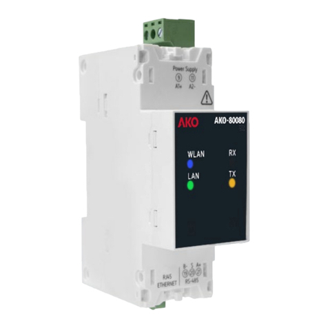
AKO AKO-80080 V2 User manual

8008H022 Ed. 02
Instructions
AKO-80080 V2
AKO ELECTROMECÁNICA, S.A.L.
Avenida Roquetes, 30-38
08812 • Sant Pere de Ribes.
Barcelona • Spain.
www.ako.com
We reserve the right to supply materials slightly different to those described in
our Data Sheets. Updated information in our website.
358008022 Rev.01 2023
Description
The AKO-80080 V2 is a gateway designed to convert the physical environment (RS-485) to Ethernet and/or Wi-Fi. The equipment has a web server from which the user can
fully adjust the equipment's settings.
Warnings
-Using the equipment while failing to respect the manufacturer's instructions may alter the apparatus' safety requirements.ng the equipment while failing to respect the manufacturer's instructions may alter the apparatus' safety requirements.
-The equipment should be installed in a place protected from vibrations, water and corrosive gases, where the ambient temperature does not exceed the value-The equipment should be installed in a place protected from vibrations, water and corrosive gases, where the ambient temperature does not exceed the value
indicated in the technical data.indicated in the technical data.
-To ensure the equipment is used safely, it is essential that the people handling it follow the safety measures set out in the regulations of the countries where it is being-To ensure the equipment is used safely, it is essential that the people handling it follow the safety measures set out in the regulations of the countries where it is being
used, wearing any necessary personal protective equipment (approved rubber gloves, facial protection and fireproof clothing) to prevent injuries caused by discharge orused, wearing any necessary personal protective equipment (approved rubber gloves, facial protection and fireproof clothing) to prevent injuries caused by discharge or
electric arc owing to exposure to conductors with a current, and observing the different warnings given in this instruction manual.electric arc owing to exposure to conductors with a current, and observing the different warnings given in this instruction manual.
-Before carrying out any maintenance, repair or handling tasks involving any of the equipment’s connections, the apparatus should be disconnected from all power sup--Before carrying out any maintenance, repair or handling tasks involving any of the equipment’s connections, the apparatus should be disconnected from all power sup-
plies, including the unit’s own power supply.When it is suspected that the equipment has malfunctioned, please contact the Post-Sale Servicplies, including the unit’s own power supply.When it is suspected that the equipment has malfunctioned, please contact the Post-Sale Service.
en
WiringInstallation
The equipment must be installed inside an electrical panel
or wraparound, with DIN rail fixing (IEC 60715).
The equipment must be connected to a protected power
supply circuit with Class M or gL-type fuses (IEC 60269),
comprised between 1 and 2 A. It must be equipped with a
magnetothermic switch or equivalent device to disconnect
the equipment from the power supply network.
The power supply circuit must be connected using a cable
with a minimum cross-section of 1 mm2.
With the equipment connected, the terminals,
opening covers and removing components may
provide access to parts that are hazardous to
touch. The equipment must not be used until it
has been fully installed.
100 - 264 V~
50 - 60 Hz
Ethernet
Tr-
Tr+
GND
MODBUS
1
8
2
3
6
7
4
5
1. Power strip: 100-240 VAC / 50 - 60 Hz.
2. WLAN indicator (Blue): Indicates that the WiFi con-
nection is active.
3. RX indicator (Orange): Indicates data frames are
received.
4. TX indicator (Orange): Indicates data frames are
sent.
5. LAN indicator (Green): Indicates that the Ethernet
connection is active.
6. Alarm indicator (Red): Failure in receiving data
frames.
7. Power indicator (White): Indicates that the equip-
ment is powered.
8. MODBUS communication strip.
If the power (7) and alarm (6) indicators flash
quickly and simultaneously, the device is be-
ing updated.
Operation
Access settings
To set-up the AKO-80040 V2 you must connect to it using a computer or mobile
device (smartphone or tablet):
• Ensure the device is powered.
• Connect to the device’s WiFi network:
Name: AKO-80080V2_(last 4 digits of the serial number)
Password: Last 8 digits of the device’s serial number.
• Open a web browser and enter the following IP address in the address bar:
192.168.222.1.
• Enter the following access information:
Name: admin
Password: admin
Assign an IP
We recommend you assign a fixed IP to the AKO-80080
V2 converter. To do so:
• Access the “Communications” section (A).
• Disable the DHCP function (B).
• Fill in the sections “Ethernet IP” (IP address), “Ether-
net Netmask” and “Ethernet gateway” with the cor-
responding information (C). If you have any questions,
contact your system manager.
• Press the “Save” button (D) to save your changes.
Change password
For safety reasons, we recommend changing the settings
access password:
• Access the “Security” section (E).
• Enter the current password (“admin” by default) (F).
• Enter the new password twice (G).
• Press the “Save” button (H) to save your changes..
A B
D
C
E
F
H
G
Technical specifications
Power supply............................................................100 - 264 V~ 50/60 Hz 2.7 VA
Installation category..................................................................................... CAT III
Work environment................................................................................-20 to 60 ºC
Storage environment ............................................................................-20 to 70 ºC
Relative humidity (no condensation) ..........................................................5 - 95 %
Maximum altitude.......................................................................................2000 m
Degree of protection ..........................................................IP30, frontal IP40 | IK08
Degree of pollution .............................................................................................. 2
Fixing ........................................................................................................ DIN rail
Connections........Screwed terminals for cables with a cross-section of up to 2.5 mm
RS-485 interface
Fieldbus ...................................................................................................... RS-485
Speed........................................4800 / 9600 / 19200 / 38400 / 57600 / 11520 bps
Data bits.............................................................................................................. 8
Stop bits ......................................................................................................... 1 / 2
Parity............................................................................................none / even / odd
Ethernet interface
Type................................................. Ethernet 10BaseT - 100BaseTX auto-detection
Protocol .................................TCP - UDP - Modbus TCP - HTTP (Web server) - REST
Network connection mode.........................................DHCP ON/OFF (ON by default)
WiFi communications
Band..........................................................................................................2.4 GHz
Standards................................................................................IEEE 802.11 b / g / n
Maximum transmit power: IEE 802.11 b: ....................................20 dBm
IEE 802.11 n: ....................................14 dBm
Connection
44
70
45
5
35.7
90
35
109.45
Dimensions
Weight: 126 g
The AKO-5010 allows up to 5 AKO-80080 V2 converters and the AKO-5025, AKO-5041 and AKO-5051 allows up to 10.
Terminating resistors are not required.
LAN
21
20
A1
19
A2
Tr+
Tr+
GND
GND
Tr-
Tr-
AKO-80080 V2
Maximum of 25 computers
100-264 V~
50 / 60 Hz
1000 m
AKO-5025
AKOControl
AKOGas
AKOCoreAKOCore
AKOCore AKOCore
Tr+
GND
Tr-
Tr+
GND
Tr-
Tr+
GND
Tr-
Tr+
GND
Tr-
Tr+
GND
Tr-
Tr+
GND
Tr-
Ethernet
TCP/IP
Switch
21
20
A1
19
A2
AKO-80080 V2
100-264 V~
50 / 60 Hz
CORECORE
Simplified declaration of conformity
Via this document, AKO Electromecánica S.A.L. hereby declares that the AKO-80080 radio equipment complies with Directive 2014/53/EU.
The full text of the EU declaration of conformity is available at the following web address: https://help.ako.com/en/manuals/declaracion-ue-de-conformidad

Other AKO Gateway manuals

AKO 80080 V2 User manual

AKO

AKO 80080 V2 User manual

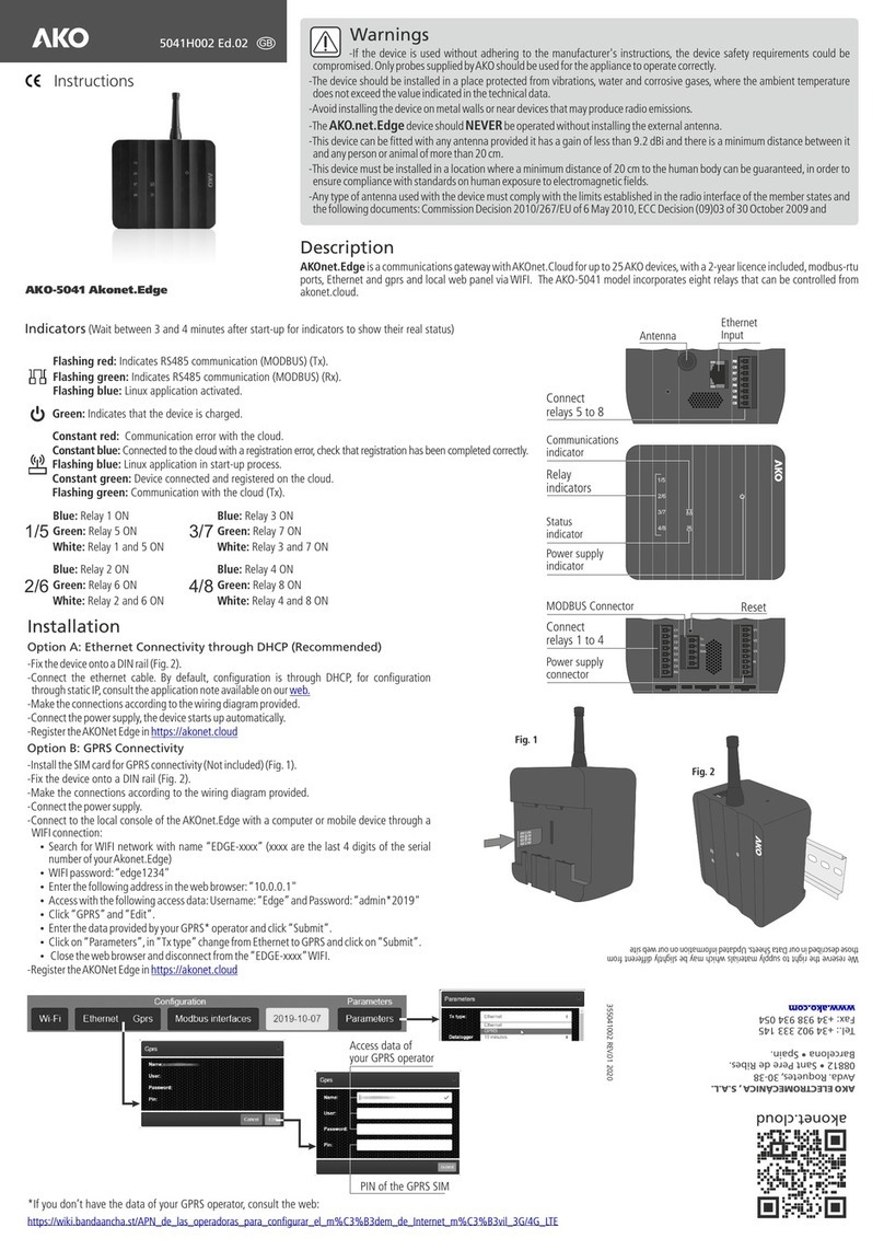
AKO Akonet.Edge AKO-5041 User manual

AKO

AKO Akonet.Edge AKO-5041 User manual

Popular Gateway manuals by other brands

Peak IPEH-004010 quick start guide

Peak

Peak IPEH-004010 quick start guide

IntesisBox IBOX-BAC-DALI user manual

IntesisBox

IntesisBox IBOX-BAC-DALI user manual

Matrix SETU ATA211 SIP-FXS-FXO System manual

Matrix

Matrix SETU ATA211 SIP-FXS-FXO System manual

AT&T U-verse TV Self-installation guide

AT&T

AT&T U-verse TV Self-installation guide

IME Milesight UG56 quick guide

IME

IME Milesight UG56 quick guide

Comelit Comelit Hub Technical manual

Comelit

Comelit Comelit Hub Technical manual

TempAlert TM-WIFI440-Z user manual

TempAlert

TempAlert TM-WIFI440-Z user manual

AudioCodes Mediant 800B user manual

AudioCodes

AudioCodes Mediant 800B user manual

Automated Logic LGRM-E Technical instructions

Automated Logic

Automated Logic LGRM-E Technical instructions

RTA 460ECUSB-NNCU Product user guide

RTA

RTA 460ECUSB-NNCU Product user guide

Cisco RFGW-10 Hardware installation guide

Cisco

Cisco RFGW-10 Hardware installation guide

ETC Net3 Conductor Setup guide

ETC

ETC Net3 Conductor Setup guide

ActionTec R1524SU user manual

ActionTec

ActionTec R1524SU user manual

AT&T NVG589 Self-installation guide

AT&T

AT&T NVG589 Self-installation guide

Panasonic KX-TDA3480 Programming guide

Panasonic

Panasonic KX-TDA3480 Programming guide

SMC Sierra Monitor FieldServer QuickServer FS-QS-2 0 Series manual

SMC Sierra Monitor

SMC Sierra Monitor FieldServer QuickServer FS-QS-2 0 Series manual

Banner SureCross DX80 product manual

Banner

Banner SureCross DX80 product manual

Dialogic 1000 Series user guide

Dialogic

Dialogic 1000 Series user guide

manuals.online logo
manuals.online logoBrands
  • About & Mission
  • Contact us
  • Privacy Policy
  • Terms and Conditions

Copyright 2025 Manuals.Online. All Rights Reserved.