AKO AKO-17609 User manual

PROMet Three-Phase Panels
User Manual
AKO-1760x, AKO-1761x, AKO-1762x
GB
1760H902 Ed.02

Index
Chapter 1: Recommendations
Chapter 2: Installation
Chapter 3: Wiring
Chapter 4: Comparative table
Chapter 5: Parameter configuration
Chapter 6: Operation
Chapter 6.2: Controls
Chapter 7: Wiring diagrams (Nomenclature)
Chapter 7.2: Control
Chapter 6.1: Description
Chapter 6.3: Indicators
Chapter 7.1: General input (Power)
Chapter 7.3.1: Controller (Only from AKO-17609 to 17616)
Chapter 7.3.2: Controller (Only from AKO-17617 to 17624)
Page 3
Page 4
Page 5
Page 9
Page 9
Page 14
Page 15
Page 15
Page 18
Page 14
Page 15
Page 16
Page 20
Page 21
AKO Electromecànica thanks you and congratulates you on the purchase of our product, the development and manufacture of
which involved the most innovative technologies, as well as rigorous production and quality control processes.
Our commitment to achieving customer satisfaction and our continuous efforts to improve day by day are confirmed by the various
quality certificates obtained.
This is a high performance, technologically advanced product. Its operation and the final performance achieved will depend, to a
great extent, on correct planning, installation, configuration and commissioning. Please read this manual carefully before pro-
ceeding to install it and respect the instructions in the manual at all times.
Only qualified personnel may install the product or carry out technical support.
This product has been developed for its use in the applications described in its manual, AKO Electromecànica does not guarantee
its operation in any use not foreseen in this document, and will not take any responsibility in any event for damage of any type that
might be caused by incorrect use, configuration, installation or start-up.
Complying with and enforcing the regulations applying to installations where our products are destined to be used is the
responsibility of the installer and the customer. AKO Electromecànica accepts no liability for damage which may occur due to failure
to comply with these regulations. Rigorously follow the instructions described in this manual.
In order to extend the lifetime of our products to the maximum, the following points must be observed:
Do not expose electronic equipment to dust, dirt, water, rain, moisture, high temperatures, chemical agents or corrosive substances
of any type.
Do not subject equipment to knocks or vibrations or attempt to handle them in any way differently to that indicated
in the manual.
Do not under any circumstances exceed the specifications and limitations indicated in the manual.
Respect the indicated environmental conditions for operation and storage at all times.
During installation and on completion of this, avoid the presence of loose, broken or unprotected cables or cables in
poor condition. These may constitute a risk for the equipment and its users.
AKO Electromecànica reserves the right to make any modification to the documentation and the product without prior notification.
2

1.- RECOMMENDATIONS
Disconnect the voltage before carrying out any operations inside the electrical panel.
All wiring should be according to current standards and should be carried out by authorised staff.
Only carry out the wiring foreseen in the wiring diagrams.
Using the electrical panel not observing the manufacturer's instructions may alter the appliance's safety requirements.
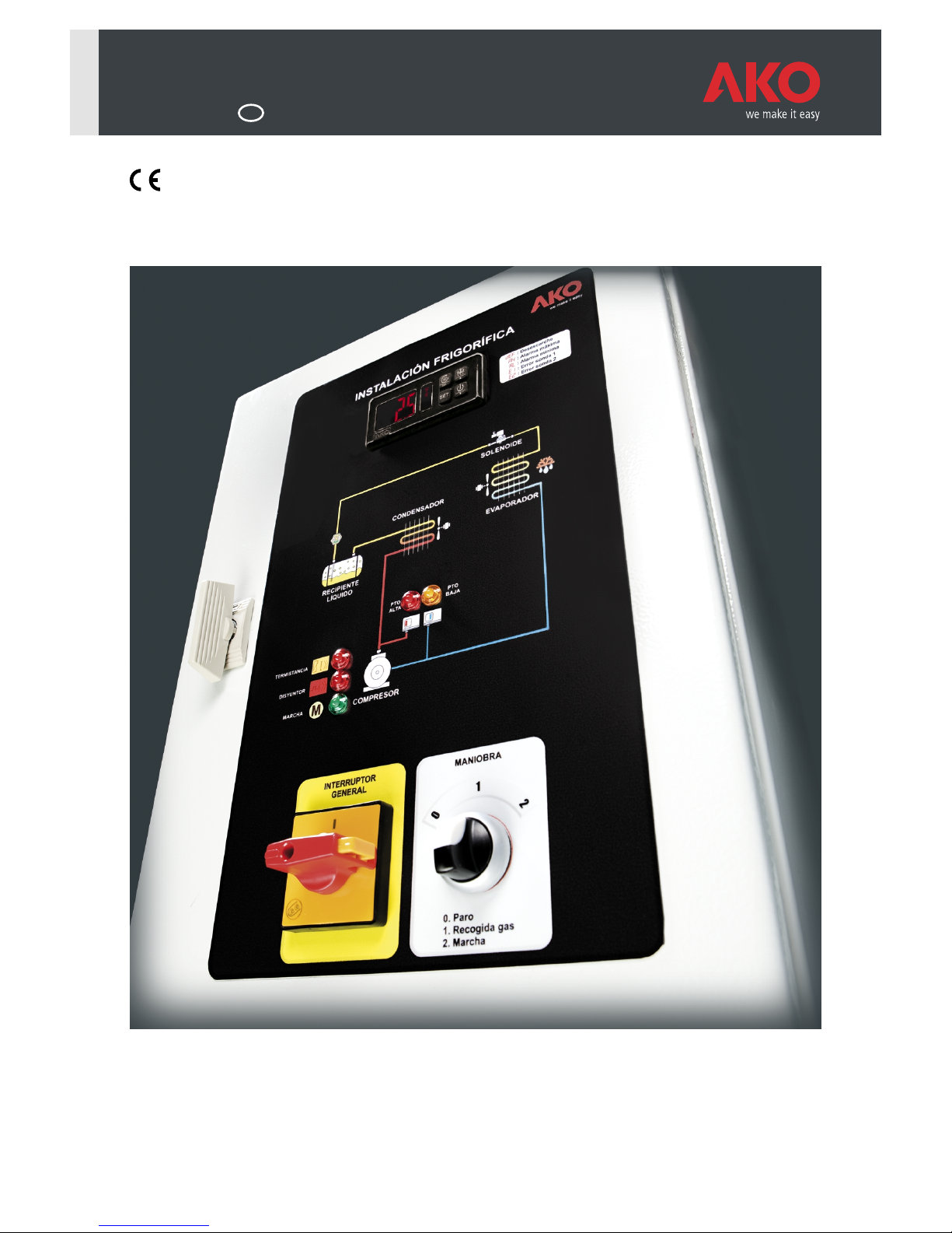
Panel installation:
It is advisable to leave a clean safety space without obstacles around the panel.
Do not knock or move the panel abruptly.
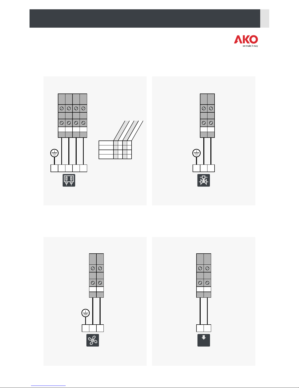
Carry out the wiring according to the installation manual.
The probes and their cables should NEVER be installed in a conduit together with power, control or feeder cables.
The earth terminals that the panels contain are installed to guarantee the continuity of earthing, however, earthing is
not carried out by the terminal and should be carried out outside the panel.
The neutral ratings are of the TT type. The IT rating should not be used.
Circuit breakers (protective switches) are of the phase/s + neutral, curve C type, guaranteeing switching and protection
against overcurrent.
Close the panel when your are not working on it.
Residual current protection outside the electrical panel according to low voltage electrotechnical regulations.
The panels have been tested using European standard IEC 60439-1.
Checks before starting the panel up:
Power supply voltages and frequencies will be the ones that figure in the "Technical specifications" section.
Check that there are no loose parts or foreign bodies on connections or switchgear.
Check that there is no dust or damp inside the panel.
Check the correct fastening of the switchgear and components.
Check the correct tightening of the screws and power connections.
Check the correct connection of the power conductors.
Check the correct insulation of the outer lines and that they do not mechanically force the inner connections of the panel.
Check that the maximum current of the Q1 current breaker.
Before starting the installation up, we recommend preheating the compressor's housing (Page 15).
Checks during the panel start-up:
Check that no electric arcs occur.
Check that the relays or contactors do not produce ratios.
Check that there is no overheating in cables, controllers and the rest of the switchgear.
Checks after the first 24 hours of operation:
Check that no overheating occurs.
Retighten screws and power connections.
Periodical preventive maintenance:
The panel should remain closed using its lock.
Retighten the power connections once a year.
Check the wear of the switchgear once a year.
Clean the outer surface of the panel with a soft cloth, water and detergent. Do not use abrasive detergents, petrol,
white spirits or solvents.
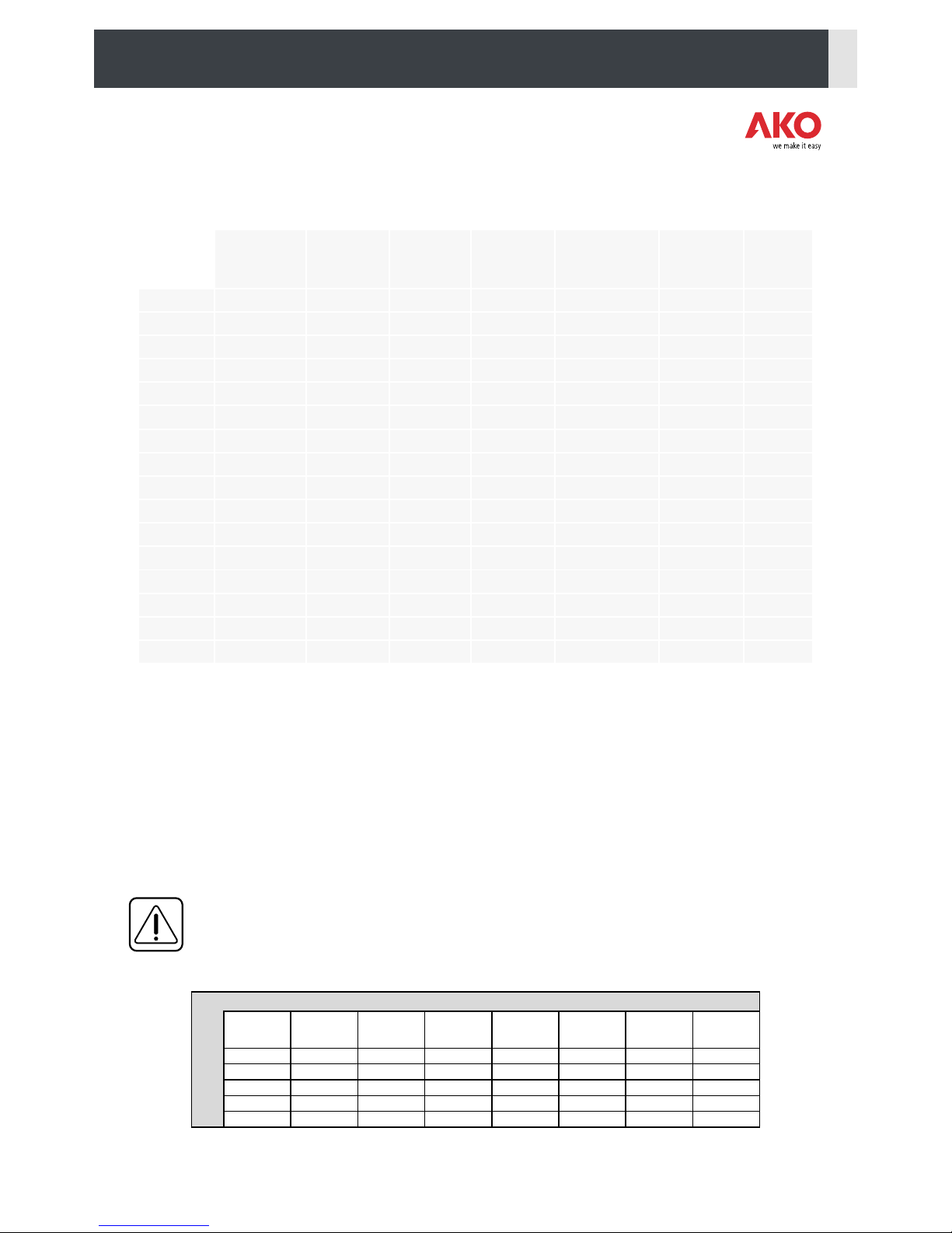
Technical data:
Working ambient temperature: -5 ºC to 40 ºC
Rated isolation voltage Ui = 440 V~
Electrical panels with degree of protection Ext./Int.: IP 54/20
CEM 1 Environment
Terminals for copper conductors
Resistance to short-circuits Icc=6 kA
Cable isolation voltage:
Operation: 500V (Halogen free)
Power: 750V (Halogen free)
3

2.- INSTALLATION
- Remove the four silicone protections (1).
- Make 4 holes on the wall with the dimensions indicated in the drawing.
- Fasten the panel to the wall using 4 suitable screws, washers and plugs.
- Before making the wiring, remove the bottom cover (2) and make suitable holes in it for the cable entry.
Use a gland to maintain the indicated degree of protection.
- Assemble the cover again with the glands. Do not forget to install the sealing gasket correctly (3).
- Wire all the elements, passing the cables through the glands and following the diagrams in the “Wiring” chapter.
- Correctly adjust the maximum current of the Q1 current breaker.
1
2
3
250 350*
250
*Only panels with output for defrost resistor
4

COMPRESSOR POWER SUPPLY INPUT
U V W
U
PE V W
COMPRESSOR
3.- WIRING
O
I
1
2
5
6
N
N
L1
T1
L3
T3
TT 400 Vac - 50Hz
L1 L2 L3 N
According to model, see table on page 9.
DEFROST RESISTORS
DEFROST
RESISTOR
R1 R2 R3 N
L1 L3
L2 N
Max. 20A
FAN 1
CONDENSER
1 2
LN
PE
CONDENSER
FAN
1
Maximum
consumption is
indicated in the table
on page 9.
Max. 1.5A (2.8A if not
using the second fan,
terminals 5 and 6)
5

FAN 2
CONDENSER
5 6
FAN
CONDENSER
LN
PE
2
FAN CONTROL PRESSOSTAT
CONDENSER
14
3 4
PRESSOSTAT
FAN CONTROL
Terminal equivalence
table
Input
Terminals
Output
Alarm
1
1
A
1
4
4
C
4
2
2
B
2
DANFOS
RANCO
ALCO
PENN
Manufacturers
THERMISTORS
THERMISTORS
N14 1112
L
7 8 9 10
PE
CRANKCASE RESISTOR
LN
11 12
CRANKCASE
RESISTOR
If the installation does
not have a thermistor
a bridge should be
made between
terminals 7 and 10,
while terminals 8 and
9 will remain free.
The bridge can be
replaced by an external
command.
Max. 1.5A
6

13 14 15 16
AB C D
HIGH / LOW
PRESSOSTAT
HIGH / LOW PRESSOSTAT
PE
Terminal equivalence
table
Input
Terminals
Output
L. Pres. Alarm
H. Pres. Alarm
A
21
A
1
C
14
C
4
B
12
B
2
D
24
D
3
DANFOS
RANCO
ALCO
PENN
Manufacturers
LIQUID SOLENOID VALVE
20 21
LIQUID SOLENOID
VALVE
21
PE
EVAPORATOR FAN
22 23
EVAPORATOR
FAN
LN
PE
230Vac / Max. 3A
In ALCO pressostats a
bridge has to be made
between terminals 22
and 11, to follow the
protection series.
AUXILIIARY OUTPUT
LN
AUXILIARY
POWER SUPPLY OUTPUT
24 25
AUX.
230Vac /
Max. 1500W
7

PROBES
Mesh
28 2926 27
PROBE 1
Environment
PROBE 2
Evaporator
NTC NTC
RESISTOR
THERMOSTAT
RESISTOR THERMOSTAT
30 32
According to model, see table on page 9.
NC
CPE
CONDENSOR AND EVAPORATOR FANS
24 25
In models with
AKO-14323
microcontroller (see
table), if the installation
does not have a resistor
thermostat, make a
bridge between
terminals 30 and 32.
FANS
LN
PE
Max. 6A
14
CONDENSATION
PRESSOTAT
-The sum of the consumption of the condenser and evaporator fans should not exceed
5A. If this is exceeded, the fans will be distributed among their corresponding outputs
and the auxiliary output (Terminals 24 and 25) so that the maximum allowed con-
sumption is not exceeded in any of them.
The fans connected to the auxiliary output should include a condensation pressostat
for control, as shown in the following diagram.
-If the fan does not have a pressostat, connect it together with the compressor.
The maximum consumption of the Compressor-Fan group should be in
accordance with the adjustment of the Q1 motor protector.
Terminal equivalence
table
Input
Terminals
Output
Alarm
1
1
A
1
4
4
C
4
2
2
B
2
DANFOS
RANCO
ALCO
PENN
Manufacturers
8

4.- COMPARATIVE TABLE
Condenser
unit
power
Controller
Defrost
resistors
Defrost
resistor
thermostat
I max.
fans
(Comp. + Evap.)
I max.
defrost
resistors
I max.
auxiliary
output
AKO-17609
1 to 1.6 A
AKO-D14223
No
No
5 A
6 A
AKO-17610
1.6 to 2.5 A
AKO-D14223
No
No
5 A
6 A
AKO-17611
2.5 to 4 A
AKO-D14223
No
No
5 A
6 A
AKO-17612
4 to 6.3 A
AKO-D14223
No
No
5 A
6 A
AKO-17613
6.3 to 10 A
AKO-D14223
No
No
5 A
6 A
AKO-17614
10 to 16 A
AKO-D14223
No
No
5 A
6 A
AKO-17615
16 to 20 A
AKO-D14223
No
No
5 A
6 A
AKO-17616
20 to 25 A
AKO-D14223
No
No
5 A
6 A
AKO-17617
1 to 1.6 A
AKO-D14323
Yes
5 A
20 A
6 A
AKO-17618
1.6 to 2.5 A
AKO-D14323
Yes
Yes
5 A
20 A
6 A
AKO-17619
2.5 to 4 A
AKO-D14323
Yes
Yes
5 A
20 A
6 A
AKO-17620
4 to 6.3 A
AKO-D14323
Yes
Yes
5 A
20 A
6 A
AKO-17621
6.3 to 10 A
AKO-D14323
Yes
Yes
5 A
20 A
6 A
AKO-17622
10 to 16 A
AKO-D14323
Yes
Yes
5 A
20 A
6 A
AKO-17623
16 to 20 A
AKO-D14323
Yes
Yes
5 A
20 A
6 A
AKO-17624
20 to 25 A
v
Yes
Yes
5 A
20 A
6 A
5.- PARAMETER CONFIGURATION
The AKO microcontroller has been factory configured for optimum operation in most refrigerated installations.
Refer to the following table to check that this configuration is adapted to your needs. If you want to change a parameter,
refer to the microcontroller's manual.
The unit operating parameters are organised in different groups or families according to their function.
The Default values column indicates the factory configured default parameter. The “PARAMETERS ACCORDING TO
APPLICATION” indicates the variable parameters depending on the application chosen in parameter P3.
Unless otherwise indicated, the temperature values are expressed in ºC. (Equivalent temperature in ºF)
IMPORTANT: The AKO microcontroller is factory configured to obtain the best operation in combination
with the panel, therefore, its configuration is slightly different to the one shown in its manual. Refer to the
following table to know its real configuration.
DEFAULT PARAMETERS, DEPENDING ON APPLICATION (P3)
2 -18 10 0 3 12 21 37
8 0 30 8 8 30 99 -
20 20 20 20 20 20 0 -
1011111-
444424 24 96 -
SP
d1
F3
d0
F0
8
Heat/
Incubators
4
Fresh
fish
6
Bottle
racks
7
Cold
5
Soft
drinks
3
Fruits and
vegetables
2
Frozen
foods
1
Multipurpose
9
Yes
Yes
Yes
Yes

Description
Units
Min.
Default values
Max.
AKO-17609
to
17616
AKO-17617
to
17624
SP
Temperature Adjustment (Set Point)
(limits depending on probe type)
(ºC/ºF)
-50
2
-18
99
C0
Calibrating probe 1 (Offset)
(ºC/ºF)
-20.0
0.0
20.0
C1
Probe 1 differential (Histeresis)
(ºC/ºF)
0.1
2.0
20.0
C2
Upper blocking of the set point
(cannot be set above this value)
(ºC/ºF)
C3
99
99
C3
Lower blocking of the set point
(cannot be set below this value)
(ºC/ºF)
-50
-50
C2
C4
Type of delay for protection of the compressor:
0=OFF/ON (since the last disconnection);
1=ON (since start-up/reset);
2=OFF-ON/ON-OFF (since the last shut-down /start-up)
0
0
2
C5
Protection delay time (value of the option selected in parameter C4)
(min.)
0
0
120
C6
Status of COOL relay with probe fault
0=OFF; 1=ON; 2=Average based on last 24 hours prior to probe fault;
3=ON-OFF as prog. C7 and C8 (in heat mode always OFF)
0
0
3
C7
Time relay ON in case of faulty probe
(If C7=0 and C8¹0, the relay will always be OFF deenergised)
(min.)
0
10
120
C8
Time relay OFF in case of fault of probe 1
(If C8=0 and C7¹0, the relay will always be ON energised)
(min.)
0
5
120
C9
Maximum duration of fast freezing mode. (0=off)
(h.)
0
0
48
C10
Change set point (SP) in fast freezing mode, when it reaches this point
(SP + C10) returns to normal. (SP+C10 ³ C3) (0=OFF)
(ºC/ºF)
0
0
C3-SP
C11
Length of inactivity at digital input to activate ECO mode
(Only if P10 or P11=1 and P0=0) (0=OFF)
(h.)
0
0
24
C12
Change set point (SP) in ECO mode (SP+C12 C2) (0=off)£
(ºC/ºF)
0
0
C2-SP
EP
Exit to Level 1
Level 2
Level 1.- Control
10

Description
Units
Min.
Default values
Max.
AKO-17609
to
17616
AKO-17617
to
17624
d0
Defrost frequency (Time between two starts)
(h.)
0
6
96
d1
Maximum defrost duration (0=defrost deactivated)
(min.)
0
30
255
d2
Type of message during defrost:
0=Current temperature; 1=Temperature at start of defrost;
2=Display dEF message
0
2
2
d3
Maximum duration of message (time added at the end of the defrost)
(min.)
0
5
255
d4
Defrost end temperature (probe 2) (If P4 ¹ 1)
(ºC/ºF)
-50
8
99,9
d5
Defrost on equipment start-up
0=NO, First defrost as per d0 1=YES, First defrost as per d6
0
0
1
d6
Defrost start delay on equipment start-up
(min.)
0
0
255
d7
Defrost type: 0=Resistors 1=Inverted cycle
2=Fan / air 3=Compressor off
0
0
3
d8
Calculated time between defrost periods:
0=Total actual time; 1 =Sum of times the compressor is on
0
0
1
d9
Drip time at end of defrost (compressor and fans off) (if P4 ¹ 1)
(min.)
0
0
1
255
EP
Exit to Level 1
Level 1.- DEFROST Control
Level 2
Description
Units
Min.
Default values
Max.
AKO-17609
to
17616
AKO-17617
to
17624
F0
Fan shut-down temperature as per probe 2 (if P4 ¹ 1)
(ºC/ºF)
-50
50
99,9
F1
Probe 2 differential (If P4 ¹ 1)
(ºC/ºF)
0,1
2,0
20,0
F2
Stop fans when stopping compressor 0=No, 1=Yes
0
1
1
F3
Fan status during defrost: 0=Off; 1=On
0
1
0
1
F4
Starting delay after defrost (if F3=0)
Will only operate if it is higher than d9
(min.)
0
0
3
99
F5
Stop fans on opening the door 0=No, 1=Yes
(Requires a digital input configured as port P10 or P11=1)
0
0
1
EP
Exit to Level 1
Level 2
Level 1.- Fan control (Evaporator)
11

Description
Units
Min.
Default values
Max.
AKO-17609
to
17616
AKO-17617
to
17624
A0
Configuration of temperature alarms: 0=Relative to SP; 1=Absolute
0
0
1
A1
Maximum alarm probe 1 (must be greater than SP)
(ºC/ºF)
A2
99,9
99,9
A2
Minimum alarm probe 1 (must be less than SP)
(min.)
-50
-50
A1
A3
Temperature alarm delay during start-up
(min.)
0
0
120
A4
Temperature alarm delay after completion of a defrost
(min.)
0
0
99
A5
Temperature alarm delay after reaching the value of A1 or A2
(min.)
0
30
99
A6
External alarm delay when receiving digital input signal
(P10 or P11=2 or 3)
(min.)
0
0
120
A7
Desactivation delay of the external alarm when the signal of the digital
input disappears (P10 or P11=2 or 3)
(min.)
0
0
120
A8
Show warning if defrost is terminated by time-out 0=No, 1=Yes
0
0
1
A9
Alarm relay polarity 0=Relay ON in alarm (OFF no alarm)
1=Relay OFF on alarm (ON with no alarm)
0
0
1
A10
Temperature Alarm Differential (A1 and A2)
(ºC/ºF)
0,1
1,0
20,0
A12
Door open alarm delay (if P10 or P11=1)
(min.)
0
2
120
EP
Exit to Level 1
Level 1.- ALARMS control
Level 1.- General status
Description
Units
Min.
Default values
Max.
AKO-17609
to
17616
AKO-17617
to
17624
P1
Delay of all functions on receiving electrical power
(min.)
0
0
255
P2
Access code (password) functions
0=Inactive; 1=Block access to parameters; 2=Keyboard lock
0
0
2
P3
Set the default parameters according to the type of application
1=Multipurpose 2=Frozen 3=Fruit and Vegetables
4=Fresh Fish 5=Soft Drinks 6=Bottle Racks
7=AC 8=Heat/Incubators
0
0
8
Level 2 Level 2
12

Description
Units
Min.
Default values
Max.
AKO-17609
to
17616
AKO-17617
to
17624
P4
Selection of type of input
1=1 probe + 2 digital inputs, 2=2 probes +1 digital input
1
2
2
P5
MODBUS Address
1
1
225
P6
Configuration of AUX relay 0=Fan (only 2-relay equipment)
1=defrost 2=Alarm 3=Light
0
0
1
3
P7
Temperature display mode
0=Whole in ºC 1=One decimal in ºC
2=Whole in ºF 3=One decimal in ºF
0
1
3
P8
Probe to be displayed (as per parameter P4)
0=visualization of all the probes in sequence 1=Probe 1;
2=Probe 2 3=Probe 3
1
1
2
P10
Configuring digital input 1
0= Off 1=Door contact 2=External alarm
3=Severe external alarm 4=Slave defrost
5=Act. modo ECO 6=Act. Fast Freezing (If C9 ¹0)
0
0
6
P11
Configuring digital input 2
0= Off 1=Door contact 2=External alarm
3=Severe external alarm 4=Slave defrost
5=Act. modo ECO 6=Act. Fast Freezing (If C9 ¹0)
0
0
6
P12
Digital input polarity 1
0=Energised on closed contact, 1=Energised on open contact
0
0
1
P13
Digital input polarity 2
0=Energised on closed contact, 1=Energised on open contact
0
0
1
EP
Exit to Level 1
Level 2
Description
Units
Min.
Default values
Max.
AKO-17609
to
17616
AKO-17617
to
17624
L5
Access code (Password)
0
-
99
PU
Program version (Information)
-
Pr
Program revision (Information)
-
EP
Exit to Level 1
Level 2
Level 1.- (tid)Access and information control
13
Level 1.- (Continuación)General status

6.- OPERATION
6.1- Description
Ÿ 1. AKO microcontroller.
Ÿ 2. Microcontroller messages help.
Ÿ 3. High pressure switch indicator.
Ÿ 4. Thermistor indicator (Cond. U.).
Ÿ 5. Current breaker indicator (Cond. U.).
Ÿ 6. Compressor operating indicator.
Ÿ 7. Main switch.
Ÿ 8. Low pressure switch indicator.
Ÿ 9. Control selector.
14
SET
ESC
REFRIGERATION INSTALLATION
LIQUID
TANK
SOLENOID
CONDENSER
EVAPORATOR
COMPRESSOR
HIGH
PRES.
LOW
PRES.
RUN
we make it easy
MAIN
SWITCH
: Defrost
: Maximum Alarm
: Minimum Alarm
: Probe 1 Error
: Probe 2 Error
I
0
BREAKER
THERMISTOR
2
3
6
5
4
1
8
9
7
SWITCH OPERATION
0. Stop
1. Pump Down
2. Run

6.2- Controls
1
AKO Microcontroller (1)
Refer to the attached microcontroller manual about this device operation.
Main switch (7)
Starts up (pos.1) or stops (pos. 0) the control panel.
As a safety measure, the door cannot be opened when the panel is operating.
Control selector (9)
It allows selecting the compressor control.
ŸPosition 0 (Stop): In this position the compressor will never start to operate.
The crankcase's resistor always activates when the main switch is in
position 1.
ŸPosition 1 (Pump down): The compressor starts to operate pump down (closed liquid solenoid)
until the low pressure switch stops it.
ŸPosition 2 (Run): The installation will operate autonomously controlled by the panel.
6.3- Indicators
High pressure switch indicator (3)
Indicates the activation of the high pressure switch.
Low pressure switch indicator (8)
Indicates the activation of the low pressure switch.
Thermistor alarm indicator (4)
Indicates the activation of the compressor's thermistor.
Current breaker alarm indicator (5)
Indicates the activation of the compressor's current breaker.
Compressor operating indicator (6)
Indicates the activation of the compressor.
IMPORTANT: Before starting up the installation, we recommend preheating the compressor's crankcase,
and to do so, first turn the control selector (9) to position 0 and then the main switch (7) to position 1.
After ten minutes you can start-up the installation turning the control selector to position 2.
7.- WIRING DIAGRAMS
Nomenclature
-X(n):.....................................................................................Connection terminals
-D3/-D4: .........................................................................................AKO Controller
-FI: ...............................................................Defrost resistor protective circuit breaker
-FM: .......................................................................Control protection circuit breaker
-H(n): ..............................................................................................Indicator LEDs
-K1: ................................................................................................Auxiliary relay
-K1M: ..........................................................Compressor contactor (or condenser unit)
-K2M: ...............................................................................Defrost resistor contactor
-Q1:......................................................................................Compressor protector
-S1:...................................................................................Operating mode selector
15

7.1- General input (Power)
Connect Residual Current Protection outside
the Panel (According to R.E.B.T. - Spanish
Low Voltage Electrotechnical Regulation).
L1
-Q0
12
34
56
NN
L2
L3
N
-X-PE
-X -X
UR1
I >I >
-Q1
I >
L1
L2
L3
T1
T2
T3
1.531.54
1.611.62
VR2
WR3N
-FM -F1
21
2
4
6
1
3
5
N
N
N
N
PE
-Q0
12
34
56
NN
3
MTR
Compressor Defrost R.
Max. 20A
230V/50Hz
3F+PE
In the event of 230V
three-phase networks,
make the bridge
indicated in this box.
L1
L2
L3
N
-K1M
-K2M
1
1
2
2
3
3
4
4
5
5
7
6
6
8
PE
PE
*
* According to model, refer to table on page 9.
-F2
10A
12
NN
-X-25 -X-24
230VAC - 6A
Max. 1500W
Aux. Power Supply,
Resistors, Alarms,
Thermostats,
Condenser speed
regulator, etc.
16

>hp
High Press.
Fan 2
14
N01
L01
-3 -4 -6-5
-H9
Red
X1X2
-X-1 -X-5
-X-4
-X-3
-X-2 -X-6
1 1
Fan 1
Condenser
If a speed regulator is used for the
condenser's fans, power it from the auxiliary
output (Terminals X-24 and X-25).
Fan 2
Condenser
M M
L
L
N
N
PE
PE
Crankcase
Resistor
-X-11
-X-12
-K1M -Q1 -K1M
21
1.61
53
22
1.62
54
Controllers
Pages 26-28
Operations
Pages 16-25
Current
Breaker Alarm
17

7.2- Control
N01
L01
L
N
12
11
1
B1
Thermistor
2
B2
14
220V
Alarm
Thermistor
-H10
Red
X1X2
0
1
-S1
2
2122
-Q1
1.531.54
1314
44
2
3
-K1
-K1
51
4
2
4 3
Alarm
High P.
-H2
Red
X1X2
XX
X
2 - Run
1 - Pump down
0 - Compressor Stop
21-22
13-14
-9
-8
-7
-10
-11
-13
-12
-14
Run
Compressor
-H1
Green
X1X2
D/3
C/4
A/1
B/2
PE
High/Low
pressure
switch
LP HP
PAB
-K1M
A1A2
1 2
3 4
5 6
21 22
53 54
61 62
-X 10 9 8 7
-X 16 15 14 13
General input
Pages 14-15
18

1
M
LN
PE
Low
pressure
switch
-H3
Amber
X1X2
Solenoid
Liquid
12
-D2
-D3*
*
-D2
-D3
9
8
Fan
Evaporator
Max. 3 Amp.
4
11 910 9
N01
L01
-15
-X-21
-X-20
-X-23
-X-22
Saf. Therm.
Defrost R.
2
4
1
TTO
-X1 32 30
-K2M
A1A2
1 2
3 4
5 6
7 8
4
11 9
-D3
-K1M
6162
* Only AKO-17617/17618/17619/17620/17621/17622/17623/17624
** Only AKO-17609/17610/17611/17612/17613/17614/17615/17616
Controllers
Pages 26-28
**
*
19

7.3.1- Controller (Only AKO-17609/610/611/612/613/614/615/616)
L01
N01
-X 26
Probe
NTC
-ST2
AKO-14901
2
27 28 29
N01
L01
Mesh Mesh
AKO-D14223
C
FAN
S2
-D2
3
S1
12.6
COOL
2 4
679 10
7118
230V
-Brown
AKO-14901
-ST1
2
Probe
NTC
1
-White
-Green
General input
Pages 14-15
Control
Pages 16-17
20
This manual suits for next models
15
Table of contents