GOWIN DK START GW1NSR-LV4CQN48PC7I6 V 1.1 User manual

DK_START_GW1NSR-LV4CQN48PC7I6_V
1.1
User Guide
DBUG388-1.1E, 07/30/2021

Copyright © 2021 Guangdong Gowin Semiconductor Corporation. All Rights Reserved.
, Gowin and GOWINSEMI are trademarks of Guangdong Gowin
Semiconductor Corporation and are registered in China, the U.S. Patent and Trademark
Office, and other countries. All other words and logos identified as trademarks or service
marks are the property of their respective holders. No part of this document may be
reproduced or transmitted in any form or by any denotes, electronic, mechanical,
photocopying, recording or otherwise, without the prior written consent of GOWINSEMI.
Disclaimer
GOWINSEMI assumes no liability and provides no warranty (either expressed or implied)
and is not responsible for any damage incurred to your hardware, software, data, or
property resulting from usage of the materials or intellectual property except as outlined in
the GOWINSEMI Terms and Conditions of Sale. All information in this document should be
treated as preliminary. GOWINSEMI may make changes to this document at any time
without prior notice. Anyone relying on this documentation should contact GOWINSEMI for
the current documentation and errata.

Contents
DBUG388-1.1E
i
Contents
Contents ...............................................................................................................i
List of Figures....................................................................................................iii
List of Tables......................................................................................................iv
1About This Guide ..........................................................................................1
1.1 Purpose .............................................................................................................................. 1
1.2 Related Documents ............................................................................................................1
1.3 Terminology and Abbreviations...........................................................................................2
1.4 Support and Feedback ....................................................................................................... 2
2Development Board Introduction.................................................................3
2.1 Overview.............................................................................................................................3
2.2 A Development Board Suite................................................................................................ 4
2.3 PCB Components ...............................................................................................................5
2.4 System Block Diagram ....................................................................................................... 5
2.5 Features.............................................................................................................................. 6
2.6 Development Board Specification ......................................................................................7
3Development Board Circuit ..........................................................................9
3.1 FPGA Module ..................................................................................................................... 9
3.2 Download & Debug.............................................................................................................9
3.2.1 Overview..........................................................................................................................9
3.2.2 USB ...............................................................................................................................10
3.2.3 J- LINK...........................................................................................................................10
3.2.4 Procedure ......................................................................................................................10
3.2.5 Pinout............................................................................................................................. 11
3.3 Power Supply.................................................................................................................... 11
3.3.1 Overview........................................................................................................................ 11
3.3.2 Power System Distribution ............................................................................................ 11
3.3.3 Power Supply Pinout .....................................................................................................12

Contents
DBUG388-1.1E
ii
3.4 Clock, Reset .....................................................................................................................12
3.4.1 Overview........................................................................................................................12
3.4.2 Clock, Reset ..................................................................................................................12
3.4.3 Pinout............................................................................................................................. 12
3.5 LED ...................................................................................................................................13
3.5.1 Overview........................................................................................................................13
3.5.2 LED Circuit..................................................................................................................... 13
3.5.3 Pinout............................................................................................................................. 13
3.6 Switches ...........................................................................................................................13
3.6.1 Overview........................................................................................................................13
3.7 Key....................................................................................................................................14
3.7.1 Overview........................................................................................................................14
3.7.2 Key Circuit .....................................................................................................................14
3.7.3 Pinout............................................................................................................................. 14
3.8 GPIO .................................................................................................................................14
3.8.1 Overview........................................................................................................................14
3.8.2 GPIO Circuit................................................................................................................... 15
3.8.3 Pinout............................................................................................................................. 15
3.9 MIPI/LVDS ........................................................................................................................15
3.9.1 Overview........................................................................................................................15
3.9.2 MIPI/LVDS Circuit ..........................................................................................................16
3.9.3 Pinout............................................................................................................................. 16
3.10 RS232.............................................................................................................................18
3.10.1 Overview......................................................................................................................18
3.10.2 RS232 Circuit...............................................................................................................18
3.10.3 Pinout........................................................................................................................... 19
4Considerations ............................................................................................20
5Gowin Software ...........................................................................................21

List of Figures
DBUG388-1.1E
iii
List of Figures
Figure 2-1 DK_START_GW1NSR-LV4CQN48PC7I6_V1.1 Development Board ............................. 3
Figure 2-2 A Development Board Suite .............................................................................................4
Figure 2-3 PCB Components.............................................................................................................5
Figure 2-4 System Block Diagram .....................................................................................................5
Figure 3-1 FPGA and USB Connection Diagram...............................................................................10
Figure 3-2 FPGA and J-LINK Connection Diagram ........................................................................... 10
Figure 3-3 Power System Distribution ...............................................................................................11
Figure 3-4 Clock, Reset ..................................................................................................................... 12
Figure 3-5 LED Circuit .......................................................................................................................13
Figure 3-6 Key Circuit Diagram.......................................................................................................... 14
Figure 3-7 GPIO Circuit .....................................................................................................................15
Figure 3-8 LVDS Circuit ..................................................................................................................... 16
Figure 3-9 RS232 Download Connection .......................................................................................... 18

List of Tables
DBUG388-1.1E
iv
List of Tables
Table 1-1 Terminology and Abbreviations ..........................................................................................2
Table 2-1 Development Board Specification ......................................................................................7
Table 3-1 FPGA Download Pinout .....................................................................................................11
Table 3-2 FPGA Power Supply Pinout ...............................................................................................12
Table 3-3 FPGA Clock and Reset Pinout ........................................................................................... 12
Table 3-4 LED Pinout .........................................................................................................................13
Table 3-5 Key Circuit Pinout...............................................................................................................14
Table 3-6 J17 GPIO Pinout ................................................................................................................ 15
Table 3-7 J15 FPGA Pinout................................................................................................................ 16
Table 3-8 J16 FPGA Pinout................................................................................................................ 17
Table 3-9 RS232 Pinout .....................................................................................................................19

1 About This Guide
1.1 Purpose
DBUG388-1.1E
1(21)
1About This Guide
1.1 Purpose
DK_START_GW1NSR-LV4CQN48PC7I6_V1.1 user manual consists
of the following four parts:
1. A brief introduction to the features and hardware resources of the
development board;
2. An introduction to the function, circuit, and Pinout of each module;
3. Attentions in use of the development board;
4. An introduction to the usage of the FPGA development software.
1.2 Related Documents
You can find the related documents at www.gowinsemi.com:
1. DS821, GW1NS series FPGA Products Data Sheet
2. UG823, GW1NS series of FPGA Products Package and Pinout Manual
3. UG824, GW1NS-4&4C Pinout
4. UG290, Gowin FPGA Products Programming and Configuration Guide
5. SUG100, Gowin Software User Guide

1 About This Guide
1.3 Terminology and Abbreviations
DBUG388-1.1E
2(21)
1.3 Terminology and Abbreviations
The terminology and abbreviations used in this manual are as shown
in Table 1-1.
Table 1-1 Terminology and Abbreviations
Terminology and Abbreviations
Meaning
FPGA
Field Programmable Gate Array
MIPI
Mobile Industry Processor Interface
LVDS
Low Voltage Differential Signaling
GPIO
Gowin Programmable Input/output
MCU
Microprogrammed Control Unit
USB
Universal Serial Bus
SoC
System On Chip
JTAG
Joint Test Action Group
SRAM
Static Random Access Memory
RS232
Recommend Standard 232
ARM
Advanced RISC Machines
BSRAM
Block SRAM
SPI
Serial Peripheral Interface
PLL
Phase-locked Loop
QN48
QFN48
1.4 Support and Feedback
Gowin Semiconductor provides customers with comprehensive
technical support. If you have any questions, comments, or suggestions,
please feel free to contact us directly by the following ways.
Website: www.gowinsemi.com

2 Development Board Introduction
2.1 Overview
DBUG388-1.1E
3(21)
2Development Board Introduction
Taking GW1NSR-4C for an instance, this chapter mainly introduces
the composition, functions and features of the development board.
Compared to the GW1NS-4C, the GW1NS-4 has no built-in Cortex-M3
processor, and the GW1NSER-4C offers one-time programming and
authentication code features.
2.1 Overview
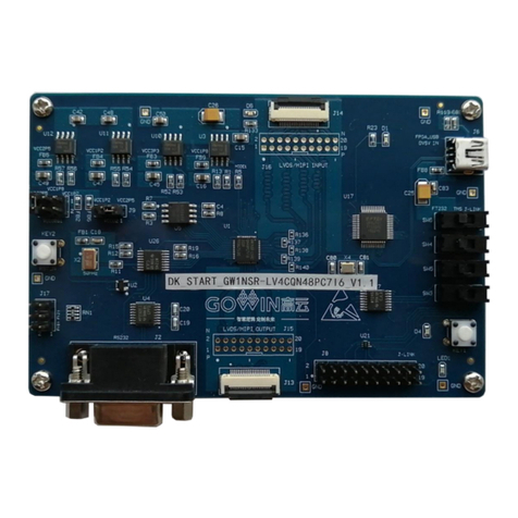
Figure 2-1 DK_START_GW1NSR-LV4CQN48PC7I6_V1.1 Development Board
The development board adopts the GW1NSR-4C SoC FPGA. SoC
FPFA is embedded with an ARM Cortex-M3 hard core processor. When the
ARM Cortex-M3 hard-core processor is employed as the core, the needs of
the Min. memory can be met. FPGA logic resources and other embedded
resources can flexibly facilitate the peripheral control functions, which

2 Development Board Introduction
2.2 A Development Board Suite
DBUG388-1.1E
4(21)
provide excellent calculation functions and exceptional system response
interrupts. They also offer high performance, low power consumption,
flexible usage, instant start-up, affordability, nonvolatile, high security, and
abundant package types, among other benefits.
The development board offers abundant external interfaces, including
MIPI/LVDS interfaces, GPIO interfaces, etc. There are also button, LED
and other resources for developers or fans to learn to use.
2.2 A Development Board Suite
A development board suite includes the following items:
DK_START_GW1NSR-LV4CQN48PC7I6_V1.1 development board
USB-Mini Data Line
Figure 2-2 A Development Board Suite
2
1
①DK_START_GW1NSR-LV4CQN48PC7I6_V1.1
Development Board
②USB-Mini Data Line

2 Development Board Introduction
2.3 PCB Components
DBUG388-1.1E
5(21)
2.3 PCB Components
Figure 2-3 PCB Components
2.5V 1.2V 3.3V 1.8V LVDS/MIPI Input
5V IN
Download
Key
OSC
GPIO
UA
RT LVDS/MIPI Output J-Link
(MCU Debug)
USB/J-Link Select
FPGA
Reset
2.4 System Block Diagram
Figure 2-4 System Block Diagram
J-Link
LDO
1.2V/1.8V/2.5V/
3.3V
1*BUTTON
OSC
50MHz
FT232HL
GPIO
1*LED
MINIUSB
4*SWITCH
5V
5 Pairs LVDS/MIPI INPUT
4Pairs
LVDS/MIPI
OUTPUT
1*UART
1*SPI Flash
FPGA

2 Development Board Introduction
2.5 Features
DBUG388-1.1E
6(21)
2.5 Features
The structure and feature of the development board are as follows:
1. FPGA
Adopts QN48 package
Up to 38 user I/O
Embedded flash, data not easily lost if power down
Abundant LUT4 resources
Multiple modes and capacities of B-SRAM
2. FPGA Configuration Modes
JTAG
AUTO BOOT
3. Clock resource
50MHz Clock Crystal Oscillator
4. Key switch and slide switch
One reset button
One key switch
5. LED
One power indicator (green)
1 LEDs (green)
One Key indicator (green)
6. Memory
1Mbit embedded Flash
64Mbit external SPI Flash
7. MIPI/LVDS
Five pairs of LVDS differential input; Four pairs of LVDS differential
output
8. GPIO
Three IOs
9. RS232
One RS232
10. LDO Power
3.3 V, 2.5V, 1.8V, and1.2V supported

2 Development Board Introduction
2.6 Development Board Specification
DBUG388-1.1E
7(21)
2.6 Development Board Specification
Table 2-1 Development Board Specification
No.
Item
Functional Description
Technical Condition
Note
1
FPGA
Core chip
–
–
2
Download
Support an USB
interface; Support
JTAG, AUTOBOOT
USB to JTAG chip
integrated on board
–
3
Power Supply
3.3 V, 2.5V, 1.8V, and
1.2 V output via LDO
circuit
Input power: 5V
Provide power for
FPGA, download circuit
and other circuits via
5V–3.3 V circuit;
Provide power for
FPGA via 5V to 2.5V
circuit;
Provide power for
FPGA via 5V–1.8V
circuit;
Provide power for
FPGA via 5 V–1.2 V
circuit.
–
4
Key Switches
Available for testing
1
–
5
Reset button
Reset for FPGA
1
–
6
LED
Test indicator, Key
indicator, Power
indicator
Four Test indicators,
green
One Power indicator,
green
One Key indicator,
green
–
7
Crystal
Oscillator
Provide 50MHz clock
for FPGA
Package5032
–
8
Memory
Flash
1Mbit embedded Flash
64Mbit external SPI
Flash
–
9
GPIO
I/O, convenient for user
extension and test
3
–
10
MIPI/LVDS
MIPI/LVDS, used for
testing
Five pairs of input, Four
pairs of output
–

2 Development Board Introduction
2.6 Development Board Specification
DBUG388-1.1E
8(21)
No.
Item
Functional Description
Technical Condition
Note
11
RS232
Used for testing
One RS232
–
12
Protection
USB interface: ESD
protection;
Power interface:
Inverse current and
over current protection
USB interface ESD
protection: ±15kV
non-contact discharge,
± 8kV contact
discharge;
Schottky diode is
connected between
positive and negative
anodes of power
interface;
2A self-recovery fuses
are connected at power
inlet
–
13
Voltage
–
Input Voltage: 5V
–
14
Humidity
–
95%
–
15
Temperature
–
Operating range: –20°~70°
–

3 Development Board Circuit
3.1 FPGA Module
DBUG388-1.1E
9(21)
3Development Board Circuit
3.1 FPGA Module
Overview
For the resources of GW1NS series of FPGA Products, please refer to
DS861, GW1NSR series of FPGA Products Data Sheet.
I/O BANK Introduction
For the I/O BANK information and package and pinout information,
please refer to UG863, GW1NSR series of FPGA Products Package and
Pinout User Guide.
3.2 Download & Debug
3.2.1 Overview
The development board provides a USB interface and a J-Link
interface. The .fs file can be downloaded to the internal SRAM or internal
Flash as needed.
Note!
When downloaded to SRAM, the data stream file will be lost if the device is powered
down, and it will need to be downloaded again after power-on.
If downloaded to flash, the data stream file will not be lost if the device is powered
down.

3 Development Board Circuit
3.2 Download & Debug
DBUG388-1.1E
10(21)
3.2.2 USB
Figure 3-1 FPGA and USB Connection Diagram
TMS
TCK
TDI
TDO
USB-to-JTAG
Chip
USB_D+
USB_D- 7
6
3
4
U1
U17
GW1NSR-LV4CQN48PC7I6_V1.1
J6
MINI USB
Socket
3.2.3 J- LINK
Figure 3-2 FPGA and J-LINK Connection Diagram
TMS
TCK
TDI
TDO
20PIN_2.54mm pitch
Double Row Pin
7
6
3
4
U1
J8
GW1NSR-LV4CQN48PC7I6_V1.1
3.2.4 Procedure
1. FPGA and MCU Download Mode:
Plug the USB cable to the development board USB interface (J6).
Note!
Before downloading, switch the SW3, SW4, SW5, and SW6 on the development
board to FT232 side.
2. MCU Debugging Mode
Connect to J8 with the J-Link simulator.
Note!
Before Debugging, switch the SW3, SW4, SW5, and SW6 on the development board
to J-Link side.

3 Development Board Circuit
3.3 Power Supply
DBUG388-1.1E
11(21)
3.2.5 Pinout
Table 3-1 FPGA Download Pinout
Signal Name
Pin No.
BANK
Description
I/O Level
TMS
6
0
JTAG Signal
3.3V/2.5V/1.2V
TCK
7
0
JTAG Signal
3.3V/2.5V/1.2V
TDI
3
0
JTAG Signal
3.3 V/2.5V/1.2V
TDO
4
0
JTAG Signal
3.3V/2.5V /1.2V
MODE0
10
0
Mode selection pin
3.3V/2.5V/1.2V
JTAGSEL_N
8
0
JTAGSEL_N
3.3V/2.5V/1.2V
DONE
9
0
One DONE indicator
3.3V/2.5V/1.2V
3.3 Power Supply
3.3.1 Overview
DC5V is input by USB interface. The TI LDO power supply chip is used
to step down voltage from 5V to 3.3V, 2.5V, 1.8V and 1.2V, which can meet
the power demand of the development board.
3.3.2 Power System Distribution
Figure 3-3 Power System Distribution
USB
Interface
DC5V Input
TPS7A7001
LDO
1.2V
TPS7A7001
LDO
3.3V
TPS7A7001
LDO
2.5V
USB2JTAG
(FT232)
UART&KEY&LED&
RST&CLK
FPGA VCCX
VCCO2(LVDS)
FPGA VCCO0&1
(LVDS)
FPGA VCC
FPGA VCCO2
VCCO0&1
(MIPI)
TPS7A7001
LDO
1.8V
FPGA VCCO3
FPGA VCCO0&1
(Flash)

3 Development Board Circuit
3.4 Clock, Reset
DBUG388-1.1E
12(21)
3.3.3 Power Supply Pinout
Table 3-2 FPGA Power Supply Pinout
Signal Name
Pin No.
BANK
Description
I/O Level
VCCO0
5
0
I/O Bank Voltage
2.5V/1.8V/1.2V
VCCO1
38
1
I/O Bank Voltage
2.5V/1.8V/1.2V
VCCO2
36
2
I/O Bank Voltage
2.5V/1.2V
VCCO3
12, 24
3
I/O Bank Voltage
1.8V
VCCX
25
-
Auxiliary voltage
2.5V
VCC
11, 37
-
Core voltage
1.2V
VSS
26
-
GND
-
3.4 Clock, Reset
3.4.1 Overview
The development board provides a 50MHz crystal oscillator connected
to the PLL input pin. This can be employed as the input clock for the PLL in
FPGA. Frequency division and multiplication of PLL can output the clock
required by the user.
3.4.2 Clock, Reset
Figure 3-4 Clock, Reset
22
23
KEY2
50MHz
ADM811
3.3V
F_RST_N
F_CLK
U1
U2
X2
GW1NSR-LV4CQN48PC7I6_V1.1
SN74
AVC4
T245
U26
3.4.3 Pinout
Table 3-3 FPGA Clock and Reset Pinout
Signal Name
Pin No.
BANK
Description
I/O Level
FPGA_CLK
22
3
50MHz crystal oscillator Input
1.8V
FPGA_RST_N
23
3
Reset Signal, Active Low
1.8V

3 Development Board Circuit
3.5 LED
DBUG388-1.1E
13(21)
3.5 LED
3.5.1 Overview
There is one green LED in the development board and users can
display the required status through the LED. There are two LEDs left to
facilitate the observation of power supply and FPGA loading status.
You can test the LEDs in the following ways:
When the FPGA corresponding pin output signal is logic low, the LED is
lit;
If the signal is high, LED is off.
3.5.2 LED Circuit
Figure 3-5 LED Circuit
LED1 33
VCC3P3
F_LED1
GW1NSR-LV4CQN48PC7I6_V1.1
U1
3.5.3 Pinout
Table 3-4 LED Pinout
Signal Name
Pin No.
BANK
Description
I/O Level
F_LED1
33
2
LED1
2.5V/1.2V
3.6 Switches
3.6.1 Overview
There are four slide switches in the development board to control
program downloading and MCU debugging. Please refer to PCB board
screen printing for specific operation instructions.
Table of contents
Other GOWIN Microcontroller manuals

GOWIN
GOWIN DK_START_GW1NSR-LX2CQN48PC5I4_V 2.1 User manual

GOWIN
GOWIN DK START GW1NSR-LV4CQN48PC7I6 V User manual

GOWIN
GOWIN GW1NR Series User manual

GOWIN
GOWIN EMPU-M1 Quick Design User manual

GOWIN
GOWIN DK START GW1N-LV9LQ144C6I5 V2.1 User manual

GOWIN
GOWIN GW2A Series Quick start guide

GOWIN
GOWIN DK Motor GW2A-LV55PG484C8I7 V3.0 User manual
Popular Microcontroller manuals by other brands

Atmel
Atmel SAM HA1G16A Xplained Pro user guide

Infineon Technologies
Infineon Technologies TriBoard TC2X3 user manual

Cypress
Cypress CY3642 quick start guide

STMicroelectronics
STMicroelectronics STM32F038C6 manual

GigaDevice Semiconductor
GigaDevice Semiconductor GD32F1 0 Series user manual

Atmel
Atmel SAM L21 Xplained Pro manual