Akuvox R48G(433) User manual

R48G(433) Android Video Phone User Manual

About this manual
Thank you for choosing Akuvox’s R48G(433) Android Video Phone. This manual is intended for end users, who need to use and
configure the door phone. It provides an overview of the most essential functions and features of the product.
Contact us
For more information about the product, please visit us at www.akuvox.com or feel free to contact us by
Telephone: +86-592-2133061 ext.7694/8162
We highly appreciate your feedback about our products

FCC Caution:
Any Changes or modifications not expressly approved by the party responsible for compliance could void the user’s authority to
operate the equipment. This device complies with part 15 of the FCC Rules. Operation is subject to the following two conditions:
(1) This device may not cause harmful interference, and (2) this device must accept any interference received, including
interference that may cause undesired operation.
Note: This equipment has been tested and found to comply with the limits for a Class B digital device, pursuant to part 15 of the FCC Rules. These
limits are designed to provide reasonable protection against harmful interference in a residential installation. This equipment generates uses and can
radiate radio frequency energy and, if not installed and used in accordance with the instructions, may cause harmful interference to radio
communications. However, there is no guarantee that interference will not occur in a particular installation. If this equipment does cause harmful
interference to radio or television reception, which can be determined by turning the equipment off and on, the user is encouraged to try to correct the
interference by one or more of the following measures:
—Reorient or relocate the receiving antenna.
—Increase the separation between the equipment and receiver.
—Connect the equipment into an outlet on a circuit different from that to which the receiver is connected.
—Consult the dealer or an experienced radio/TV technician for help.
FCC Radiation Exposure Statement:

This equipment complies with FCC radiation exposure limits set forth for an uncontrolled environment .
This transmitter must not be co‐located or operating in conjunction with any other antenna or transmitter.
This equipment should be installed and operated with minimum distance 20cm between the radiator &you body.

Content
1. Product Overview............................................................................................................................................................................................... 1
1.1. Instruction.....................................................................................................................................................................................................1
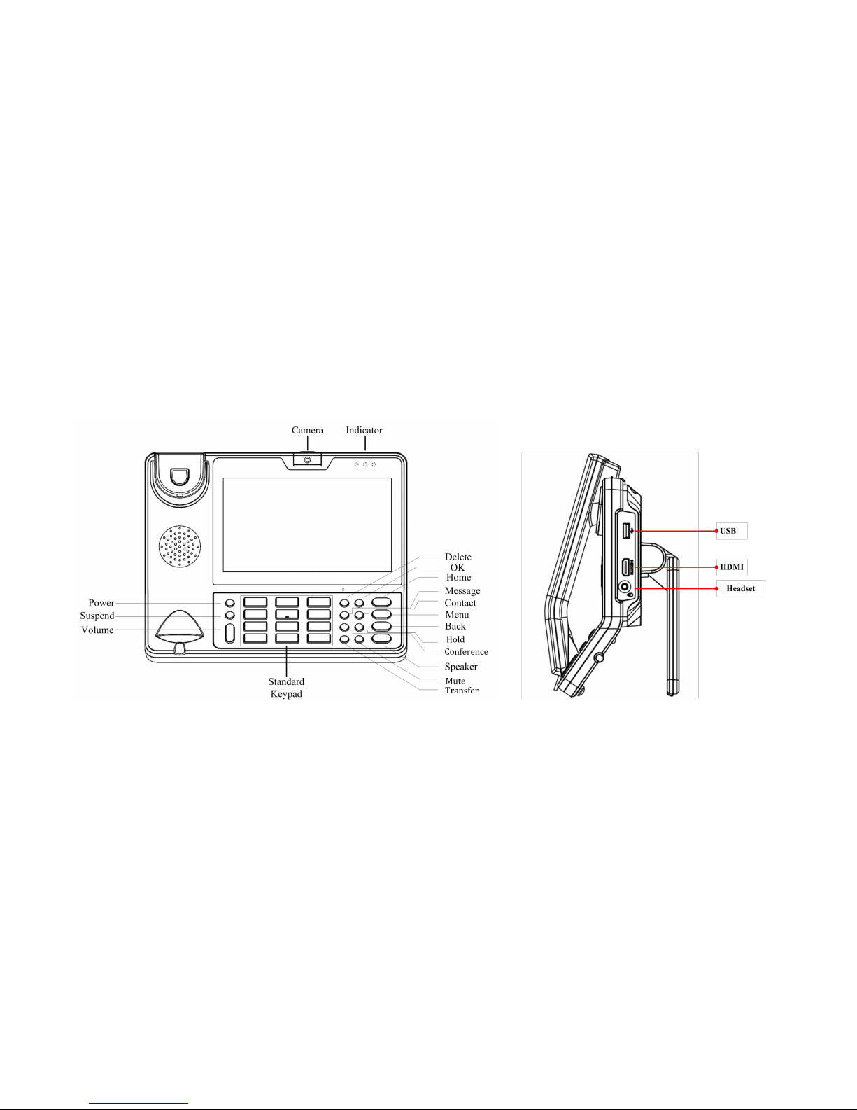
1.2. Equipment Appearance And Interface Description................................................................................................................................2
1.2.1. Interface Description........................................................................................................................................................................ 4
1.2.2. Keypad Description.......................................................................................................................................................................... 5
1.3. Pendant........................................................................................................................................................................................................ 6
1.4. Indicator........................................................................................................................................................................................................ 7
1.4.1. Indicator of R48G(433).................................................................................................................................................................... 7
1.4.2. Indicator of Pendant......................................................................................................................................................................... 7
2. Installation............................................................................................................................................................................................................ 9
2.1. Equipment Packaging................................................................................................................................................................................ 9
2.2. Connecting Video Phone.........................................................................................................................................................................10
2.3. Installation Considerations...................................................................................................................................................................... 12
3. Daily Use............................................................................................................................................................................................................. 13
3.1. Call.............................................................................................................................................................................................................. 13
3.1.1. Make A Call..................................................................................................................................................................................... 13

3.1.2. Dial Out Directly..............................................................................................................................................................................14
3.1.3. Dialing Out From Contact List...................................................................................................................................................... 15
3.1.4. Receive A Call.................................................................................................................................................................................16
3.1.5. Call Options..................................................................................................................................................................................... 17
3.1.6. Multiple Calls................................................................................................................................................................................... 19
3.1.7. RF Number...................................................................................................................................................................................... 20

1
1. Product Overview
1.1. Instruction
VP-R48G(433) is an Android-based multimedia terminal with a 7 inch
touch screen and a 1.3M CMOS sensor camera. It supports
H.264/H.263 codecs with adaptive bandwidth adjustment. The 7 inch
touch screen offers excellent user experiences such as high quality
videophone, smooth internet surfing, various Android Apps and daily
information.
VP-R48G(433) provides 2 Ethernet ports, 1USB, 1HDMI, and one
3.5mm headset/audio port.

2
1.2. Equipment Appearance And Interface Description

3

4
1.2.1. Interface Description
Interface Description
Camera Adjustable camera shooting angle, rotate down the camera to "off"
angle.
USB interface External USB storage device
Headset Connect to 3.5mm stereo headphone, headset device
HDMI Use HDMI cable to output the video to a TV screen
LAN
Network interface can be connected to a hub, switch or other network
access devices. It also supports POE(Power over Ethernet) .
PC
Share the network access from LAN port, and for PC and other
equipment connection
Power Connect to 12V adapter, Power supply
Handset Connect to handset
Lock Lock the video phone with a Laptop lock
Note: If Power over Ethernet is being used, do not plug in the AC adapter.

5
1.2.2. Keypad Description
Interface Description
Power Turn on/off the LCD, Reboot, Silent mode
Suspend Turn on/off the LCD, Reboot, Silent mode
Volume Press + or – for the phone volume adjustment
Standard
Keypad
Input the number or symbol
Function Key
Delete Delete a character before the cursor
OK Same function with soft keyboard "Enter" key
Message Optional
Contact
Enter Into the contacts list, you can view the local
contact
Conferenc
e
The first party is held in the case, according to a
conference key, the first party can be combined to
achieve a tripartite meeting
Hold To hold a call during the call

6
Transfer To transfer the current call to the third party
Mute The other party cannot heard the voice during the call
Home
Return to the main screen, and long press, it will
display recently used applications
Menu To call up the System or program setup menu
Back Return to the previous menu
Speaker Speaker
1.3. Pendant
R48G(433) pendant is used to call out the emergence number when you
need help. However, users can choose whether the pendant is needed,
based on your own needs.

7
1.4. Indicator
1.4.1. Indicator of R48G(433)
1.4.2. Indicator of Pendant
Indicator Status Description Notes
Flashing Yellow
The pendant is in low battery power
status.
The pendant powers on again.
User need to replace the battery.
Indicator Name
Icon
Status
Description
Power
ON System is under working
OFF
System is not working
Network
Connection
ON
Network(LAN Port)is connected
OFF
Network(LAN Port)is disconnected
Information
Flashing
Contains Miss Calls or Unread Message
OFF
Normal status

8
Alternate Flashing
Green and Red
(1)The pendant in factory-test
mode.
(1)If user long press the pendant
button meanwhile install the
battery, it will enter testing mode.
User need to install the battery
again and do not press the push
button during the installation.
Flashing Red
Before the pendant matches with
the phone, press pendant button.
Press the pendant to make a call
over 200 meters after it matched
with the phone.
(1)User need to match the
pendant with the phone.
(2)The maximum distance
between the matched phone
with the pendant is about 200
meters.User need to use it in
this range.

9
Flashing Green
(1)In the process of the RF
Learning. press the pendant button.
The phone will prompt RF Key
Learned.
(2)Press pendant button to make a
call after it matched with the phone.
Light off The battery runs out of power.
Idle status.
(1)User need to replace a new
battery.
2. Installation
2.1. Equipment Packaging
Name Quantity
Main Case 1
Handset 1

10
Phone Cord 1
Power Adapter 1
Ethernet Cable 1
Quick Start Guide 1
2.2. Connecting Video Phone
Connection diagram

11
Connecting to Network
Use the matched network cable to connect the LAN Port of the video phone to the Router or Switch. Viewing the top right corner of

12
the screen, if the indicator light is on, network cable is connected properly.
Connecting to PC
Use the matched network cable to connect the PC Port of the video phone to the PC. The PC can access to the internet network via
PC Port of the video phone.
2.3. Installation Considerations
This product is a desktop product, and here are some safety recommendations about the installation and the usage:
Do not use this product near water, such as: bath, washbasin, kitchen sink and other damp places, and so on;
Place the device in a place away from heat;
Place the device away from traffic areas to prevent collisions;
Please use the equipment with the matching power adapter or POE;

13
3. Daily Use
3.1. Call
3.1.1. Make A Call
Users can directly dial from the keypad, select from the contact list or
from call records to call out the number. Users can choose one of the
following steps to enter into the dialing interface.
Mode 1: Directly pick up the handset.
Mode 2: Press Speaker button on the keypad.
Mode 3: In the main screen, click icon .
Mode 4: In the main screen, select icon -> tap icon .

14
3.1.2. Dial Out Directly
1) By pressing the number keys on the dial interface or directly
pressing the number on keypad. To delete a number, press the icon
on the dial interface, or press Delete button on the keypad.
2) If you want to make an audio call, click Audio Call label. If users want
to make a video call, click Video Call label.
3) If multiple available SIP accounts are registered, when finishing
dialing, users can click line label to choose the
outgoing account for the number, as shown below.
Table of contents
Other Akuvox Telephone manuals