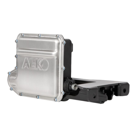
AL-KO ATC Setup guide

AL-KO ATC
OWNER INSTRUCTION MANUAL
www.al-ko.co.uk

CONTENTS
PAGE CONTENTS
1. GENERAL NOTICES
2. ATC APPLICATION & SAFETY INFORMATION
3. SYSTEM REQUIREMENTS & OPERATING INSTRUCTIONS
4. LED OPERATION
5. TROUBLESHOOTING, MAINTENANCE & WARRANTY
6. PUSH ROD REMOVAL
GENERAL NOTICES
READ AND ACT IN ACCORDANCE WITH THE
FOLLOWING OPERATING INSTRUCTIONS BEFORE
ATTEMPTING TO USE AL-KO ATC. THIS INSTRUCTION
MANUAL SHOULD BE KEPT EITHER IN THE CAR OR
CARAVAN AT ALL TIMES.
AL-KO ATC is a safety related product and, therefore,
should only be tted by an authorised AL-KO trained
technician with experience of working with electrical
installations.
Any evidence of removal or disassembly, other
than by trained technicians, will immediately invalidate
the product warranty.
1 2
AL-KO ATC TRAILER
CONTROL SYSTEM
AL-KO ATC IS AN ELECTRONIC, EMERGENCY
CONTROL SYSTEM FOR CARAVANS AND TRAILERS.
IT AUTOMATICALLY RECOGNISES CRITICAL
SWINGING MOTIONS AND APPLIES THE CARAVAN
BRAKES ACCORDINGLY TO REGAIN CONTROL OF
THE CARAVAN AND CAR.
SAFETY INFORMATION
AL-KO ATC IS A PASSIVE SAFETY PRODUCT THAT
ACTIVATES THE BRAKING SYSTEM ON THE CARAVAN IN
UNSAFE DRIVING CONDITIONS.
The driver has a responsibility under law to ensure that the
elements of towing safety are met, including driving within
the legal speed limit, consideration of road, weather and
other trafc conditions, correct loading and coupling of the
caravan.
AL-KO ATC is designed to t only on AL-KO Chassis and is
not suitable for non AL-KO Chassis.
AL-KO ATC only functions on caravans with a rigid towbar.
The electrical connection between the towing vehicle and
caravan must be in good working order.

DISPLAY ATC DIAGNOSIS WHAT TO DO OUTCOME STATUS
COLOUR CONDITION
Green ATC Active Everything Ok
Green Flashing ATC Active Self test
incomplete
Red ATC Inactive Possible to
continue journey
Red flashing ATC has detected Do not continue
a fault with ATC
connected
LED not working ATC has no power Check push rod
position as shown
LED faulty on page 5 before
continuing journey.
Drive forward to
detect movement to
complete self test
and re check LED.
Remove 12S or 13
Pin plug and wait
5 seconds.
Reconnect plug.
Remove 12S or 13
Pin plug and wait
5 seconds.
Reconnect the plug.
Remove 12S or 13
Pin plug and wait 5
seconds. Reconnect
the plug.
Check for constant
live - refer to system
requirements.
Green (Constant) Ready for journey
Green Ready for journey
Red ATC Error logfile memory
exceeded. Caravan can be
towed, but ATC will not apply
caravan brakes in the event of
instability. See below *
Green Ready for journey
Red (flashing) ATC faulty, and cannot be
driven. Remove push-rod as
shown on page 5. Consult
AL-KO, see back page for
details.
Green Ready for journey
LED not working If power ok, check push rod
position: Red line visible - do
not drive vehicle. Red line not
visible - possible to continue
journey but consult AL-KO see
back page for details.
SYSTEM
REQUIREMENTS
ATC draws power from the towing vehicle towbar and
requires connection to either:
Twin 7-Pin Connection - ATC can be connected via the
auxiliary 12S (white/grey) plug and requires power on Pins
4 (permanent supply) and 3 (earth). Please ensure that your
vehicle towbar is correctly connected to ensure correct ATC
operation. This can be checked with the use of a multimeter.
Important - A 20 amp fuse is required for the constant
12V supply to Pin 4 on the 12S socket. If only a single
fuse is tted to supply both Pins 4 and Pin 6, the power
supply capability of the installation must be checked and a
minimum fuse rating of 25 Amps must be used.
13 Pin Connection - ATC can be connected via the 13-Pin
plug and requires power on Pins 9 (permanent supply)
and 13 (earth). Please ensure that your vehicle towbar is
correctly connected to ensure correct ATC operation. This
can be checked with the use of a multimeter.
OPERATING
INSTRUCTIONS
After coupling the caravan correctly to the towing vehicle,
connect the 12N & 12S plugs or the 13 Pin plug to the towbar.
Upon connection, ATC will carry out an initial self test and
the LED light on the front fairing will light up RED. During the
self test, the sound of the push rod moving inside ATC can be
heard. When the self test is complete, the LED will turn GREEN
or ashing GREEN to signal that ATC is active.
If the LED does not change to green, then ATC is not
functioning correctly. The table provided on page 4 details what
to do in this case.
Prior to commencing any journey, ensure that the caravan
lighting is fully operational and check the vehicle is loaded
appropriately, the nose weight and tyre pressures are correct,
and conrm that the caravan is coupled to the vehicle with the
breakaway cable correctly applied.
Always re-check the ATC LED is green after any interval
during a journey, such as a service station break.
ATC LED on fairing
LED OPERATION
3 4
* ATC stores operating errors in a logle which over time will become full and will result in the solid red light
appearing. This needs to be erased and can be done easily by connecting the caravan to a 12 volt supply for a period of
12 hours. The power required to carry out this function is minimal. Most occurrences of these errors are due to power
supply problems to ATC which could be due to low voltage, or an intermittent power supply from the towbar.
1. Left Indicator
(Yellow)
2. Fog Light
(Blue)
3. Earth
(White)
4. Right Indicator
(Green)
5. Right Side Light
(Brown)
6. Brake Light
(Red)
7. Left Side Light
(Black)
8. Reverse
(Orange)
9. Permanent Live
(Red/Brown)
10. Fridge
(Blue/Brown)
11. Earth
(Blue/White)
12. Not Allocated
(None)
13. Earth
(Green/White)
7-Pin Wiring Diagram
13-Pin Wiring Diagram

Using a 17mm spanner, slacken locking nut on push rod
away from Bowden cable abutment as directed above.
TROUBLESHOOTING
Should you experience a fault with ATC, the LED light on
the fairing will change colour. Therefore, refer to the table
on page 4 and follow the instructions.
If no illumination of the LED is evident, refer to system
requirements on page 3 and check towbar wiring for
permanent supply.
In the unlikely event that you receive a red ashing LED
light and disconnecting and re-connecting the power does
not alleviate the problem, check the push rod position as
detailed below.
Locate ATC on the axle and check the position of the
push rod.
If no red line is visible, ATC is not active, and can be
driven. However, we recommend that you contact
AL-KO at the earliest convenience.
If the red line is visible on the push rod, as shown on the
left, the caravan should not be moved.
The push rod needs to be removed to deactivate ATC.
Using two 17mm spanners, the removal process is as
shown opposite.
MAINTENANCE AND WARRANTY
ATC is maintenance free and requires no servicing. In
case of any damage to ATC, please contact AL-KO. ATC is
a sealed unit and any evidence of removal of ATC or the
component parts including outer casing and xings will
immediately invalidate any product warranty.
ATC is covered by a 12 month warranty where it is
retrotted to a caravan. If ATC is tted as standard by the
vehicle manufacturer then ATC is covered for the same
duration of the vehicle warranty.
If ATC is subject to a call out under warranty and found to
comply with the relevant specication or standard, then
the cost of any testing or callout charges will be borne by
the customer. We reserve the right to request credit card
details to cover payment in advance.
REMOVAL OF PUSH ROD:
5 6
Re-apply the removed locking nut onto brake rod thread to
secure ball nut as shown above. ATC is now deactivated.
Unscrew push rod from brake rod and slide it from the guide tube.
Remove the locking nut from push rod using two 17mm spanners.

THE PREMIUM ACCESSORY RANGE
AL-KO AKS 1300 STABILISER
AL-KO SHOCK ABSORBER
AL-KO SIDE LIFT JACK
AL-KO AMS MAMMUT
AL-KO PREMIUM JOCKEY WHEEL
AL-KO AKS 3004 STABILISER
AL-KO SECURE WHEEL LOCK
AL-KO SECURITY DEVICE
QUALITY FOR LIFE
AL-KO Kober Ltd, South Warwickshire Business Park, Kineton Road, Southam, Warwickshire, CV47 OAL
Due to a policy of continuous product improvement, AL-KO reserves the right to change technical specications.
Revision Date 05/2016 Part Number 1551194
INDUSTRY LEADING SAFETY AND
SECURITY FROM THE WORLD LEADERS
IN CARAVAN CHASSIS TECHNOLOGY
Each and every AL-KO accessory is
engineered to be the very best of its kind,
providing industry leading features and
benets that complement the UK’s market
leading caravan chassis.
Used together, AL-KO Premium Accessories
provide the optimum combination; a
combination that ensures the highest levels
of safety and security
for you and your caravan.
WWW.AL-KO.CO.UK
PART OF THE AL-KO PREMIUM ACCESSORY
RANGE, AVAILABLE ON THE AL-KO WEBSITE
JOCKEY WHEELS
WHEEL CHOCKS &
CARRIERS
SECURITY DEVICES
CORNER STEADIES
SHOCK ABSORBERS
COUPLING HEADS
ATC TRAILER CONTROL
WHEEL LOCKS
HITCH COVERS
AKS STABILISERS
SPARE WHEEL
CARRIER
TOWING
ACCESSORIES
AL-KO ATC TRAILER CONTROL
Other manuals for ATC
2
Table of contents
Other AL-KO Control System manuals