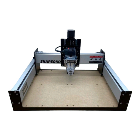
Carbide 3D Shapeoko XXL User manual

Carbide 3D
☰
Step 1 Inventory
Welcome… and
Congratulations!
You are now the proud owner of the Shapeoko XXL,
an incredibly powerful and easy-to-use CNC
machine…
NOTE: This is a note - information that point
out critical steps or reference future
information.

PROTIP: This is a Pro-Tip. Anytime you see one
of these, you will nd helpful additional
information.
WARNING: This is a warning. Information in
these boxes is very important. Pay close
attention.
Open The Box
Your Shapeoko XXL should arrive in a single box. If
you opted to include a compact router, it will be
shipped in a second box.
The primary shipping box has dimensions of 48 x
26 x 12”. The box weighs approximately 149lbs.
One side of the box has two holes (shown in the
image below) to help in removing the lid and
identifying the top of the box.
Carefully cut the tape that is sealing the box’s lid to
the box bottom before removing the lid.

Remove the components
After removing the lid, you will want to carefully
remove the various boxes, boards and wrapped
hardware inside. Some of the boxes are held tightly
in place by cardboard inserts; rocking the boxes
side-to-side can help release them from their insert
holes.
Remove and place all the items in a location where
they will not be dropped or have something
dropped on them. In particular, you will nd two
pieces of MDF board. These are the two halves of
the Shapeoko XXL’s baseplate.

The two halves are thick and tough, but until you
are ready to begin the installation it is
recommended that you store these two pieces of
MDF in a location where there is no risk of spilled
liquids until you need them.
Once the shipping box is emptied, you should have
the following 9 items:
Item Quantity Description Other Info Package
Dimensions
A 1 White
Envelope
Packing List
and Zip Ties 8.5″ x 11″
B 1
XXL Final
Assembly
Box
Components
to complete
assembly
Labeled
C 1 Labeled

Item Quantity Description Other Info Package
Dimensions
Y-Axis Left
Carriage
Left Y-Axis
Assembly
D 1 Y-Axis Right
Carriage
Right Y-Axis
Assembly Labeled
E 1 X/Z
Assembly
Contains X
and Z axis
carriages
Labeled
F 2 MDF Pieces
Found
Below
cardboard
divider
42″ x 29.75″
x 0.75″
G 1 Aluminum
Rails
Packaged 3
to a bundle
40″ x 7.5″ x
3.5
H 1 Cross Straps
Contains 3
identical
pieces
40″ x 7″ x
1.5″
I 1 End Plates
Contains 2
identical
pieces
45.5″ x 8″ x
2″

Once you’ve removed all the contents of the
shipping box, it’s time to open and inventory the
boxes and wrapped hardware. Below you will nd
a checklist that can be used to verify you have all
the hardware needed to complete your Shapeoko
XXL.
PROTIP: Your Shapeoko XXL has been carefully
hand-packed and checked for all the necessary
components you’ll need to assemble the
machine. However, sometimes errors are
made. If after completing your inventory you
nd something is missing, simply contact
Final Assembly Box

Carefully open the XXL Final Assembly Box and
inspect its contents. Many parts are packaged in
small plastic bags, and smaller bags may be
inserted into larger plastic bags for shipping
purposes. You should nd all of the following in
this box:
Item Description
ABaseplate (Wasteboard) Hardware (18
pieces: M5x25mm BHCS)
BSpindle Mount Hardware (2 pieces: M5x55,
2 pieces M5x16mm)
CBelt Clips and Hardware (6 clips, 6 pieces
M5x10mm)
D Serial Tag
E Warning Decal

Item Description
F Drag Chain Bracket Kit
G Makita Bushing Adapter
H Spindle Mount
I USB Cable
J Power Supply
K Tie Downs and Zip Ties
LTool Kit (Allen Keys: (5, 4, 3, 2, 1.5mm),
Wrenches (13, 10, 8mm)
M Power Cord
N Thread Locker (non-permanent)
O Sharpie Permanent Marker
P Belting (3 pieces: 1200mm)
Q #201 1/4” Square Endmill
R Adjustable Leveling Feet
SExtrusion Hardware (24 pieces: M6x12mm
BHCS)
Y-Axis Carriages
Open the boxes labeled Y-Axis Right and Y-Axis Left
Assembly and visually verify they match the images

below. The Right and Left Assembly components
are mirror images, but the boxes they were
shipped in are labeled; it is recommended that you
leave the carriages in their boxes until needed.
X/Z Assembly Box
Open the box labeled X/Z Assembly and visually
verify that the items inside match the image below.
After verifying the X/Z Assembly, place it back in
the box. The box should contain the X Carriage and
Z Carriage as well as a bag containing two springs
and a bag containing the Idler Assembly. The Z
Carriage is the smaller carriage that is wrapped in
packing paper.

Aluminum Rails
WARNING: These rails may look the same, but
there are subtle dierences that you need to
pay attention to.
If you do not identify the correct rails, you
will have to undo work later.
The three aluminum rails are packed together,
each rail is wrapped in a cardboard shell and
secured with plastic bands while leaving the ends
exposed.

All three wrapped aluminum rails are then secured
together as a single unit using plastic bands.
Carefully cut all plastic bands and remove the
cardboard from the three aluminum rails.
Examine the three rails and identify the following:
• Rail with the Shapeoko logo is the X-Axis Rail
• Rail with two (2x) mounting holes is the Y-LEFT
Rail
• 1x Rail with no logo and no mounting holes is
the Y-Right Rail
After verifying the three aluminum Rails, place
them back in the box until needed.

Cross Straps
Box Dimensions: (40” x 7” x 1.5”)
The Cross Straps are packed together in a single
cardboard shell and secured with plastic bands.
Carefully cut all plastic bands and remove the
cardboard from the Cross Straps. Examine the
container and identify the following:
End Plates
Box Dimensions: (45.5” x 8” x 2”)
The two (2x) End Plates are packed together in a
single cardboard shell and secured with plastic

bands. Carefully cut all plastic bands and remove
the cardboard from the End Plates. The End Plates
are identical. After verifying the End Plates, place
them back in the box until needed in Step 2.”
Note that the End Plates have inserted PEM nuts
which are threaded. These allow for the addition of
threads in plates which otherwise would not be
thick enough to have threads added, and to do so
without the manual operations of drilling a precise
hole and then forming the threads with a tap. Each
such PEM nut should be inspected to verify that the
threads in it properly formed and that it is rmly
and squarely in place.

MDF Baseplates
Box Dimensions: (42” x 19.75” x 0.75” each)
The two MDF Baseplates are identical and packed
unwrapped in the bottom of the shipping box.
NOTE: After verifying the MDF Baseplates,
store them where the risk of high humidity or
liquids spilling on them is low. MDF is sensitive
to moisture, so avoid having drinks or other
liquids in the vicinity of the Shapeoko XXL to
avoid damage to the MDF Baseplates.
You may want to consider sealing the baseplates
with a suitable nish such as spar urethane or
lacquer.

After you have veried all the components, it is
time to begin assembly. All the tools you need to
assemble your Shapeoko 3 have been included, but
a large table or workbench will be helpful during
the assembly.
The completed dimensions of the Shapeoko 3 are
45”W x 40-1/2”L x 16”H so a table larger than this is
recommended.
WARNING: The assembly should not be done
on the oor.
Back to Index Next Step
Index Baseframe
Subscribe Share

© Carbide 3D 2020, All rights reserved.

Carbide 3D
☰
Step 2 - Base Frame
Assembly
The base frame is the main sub-structure of the
machine. Supporting the rail and the gantry
system, it is important that you follow each step in
this section to ensure your machine base is stable
and secure.

Item Description Quantity
1 Front and Rear End Plate 2
2 Cross Strap 3
3 MDF Wasteboard Half 2
4 Adjustable Leveling Feet 4
5 M5 x 25mm BHCS 18
Leveling Feet
Carefully screw in the four leveling feet, two per
End Plate. The feet will only t in the outermost
nuts on the bottom of the End Plates. Turn the
Leveling Feet knobs clockwise until the top of the
threads is ush with the backside of the nut.

MDF Baseplates
Lay out the three Cross Straps (parallel to each
other and with 12” of space between them) as
shown in the image below.
The Cross Straps will be placed so the anged
edges are facing down. Note that there are two
threaded holes in the center of each Cross Strap.
Rear Baseplate
Place one MDF Baseplate across the back half of
the Cross Straps as shown in the gure below.
Place the MDF Baseplate so that the six
countersunk holes on the long side are farthest

away from the centers of the Cross Straps and the
MDF Baseplate is ush with the edges of the Cross
Straps. (This should reveal three holes running
across the middles of the Cross Straps that will be
used for the second MDF Baseplate.)
Insert 3x M5x25mm screws into the three
countersunk holes as shown in the gure below.
Turn the screws until they stop but do not tighten.
PROTIP: Some adjustability will be needed
when installing the Y-axis rails. If you fully
tighten the baseplate, the Y-axis rails will be
dicult to install.
Table of contents
Other Carbide 3D Control System manuals
Popular Control System manuals by other brands

Hayward
Hayward OmniLogic HLBASE installation manual

Hayward
Hayward HLXPROUPG Operation manual

Eurotherm
Eurotherm PC300 Installation manual and user's guide

Rockwell Automation
Rockwell Automation MSR300 instruction manual

Mitsubishi Electric
Mitsubishi Electric LMAP02-E installation manual

Helo
Helo T2 Installation and user manual

Fike
Fike CyberCat 50 10-070 Operation & maintenance manual

PS Engineering
PS Engineering PAC45 System With MultiTalker Pilot's guide and operation manual

Flint & Walling
Flint & Walling Commander Pro instructions

Spectral
Spectral SMART CONTROL IR-LINK-SYSTEM quick start guide

Invacare
Invacare LiNX REM110 user manual

Gamma Vacuum
Gamma Vacuum DIGITEL MPCq instruction manual