AL Tech DT3900 User manual

High Definition Digital TV Receiver
Instruction Manual
DT3900

2
CONTENTS
CONTENTS.........................................................................................................2
IMPORTANT SAFETY INFORMATION .......................................................3
GENERAL INFORMATION .............................................................................4
QUICK START GUIDE .....................................................................................5
REMOTE..............................................................................................................6
FRONT PANEL...................................................................................................7
REAR PANEL .....................................................................................................7
USING THE SET TOP BOX .............................................................................8
ADD NEW CHANNELS ...................................................................................8
CONNECTION ..................................................................................................9
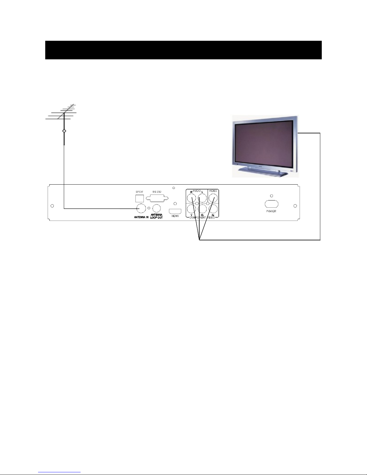
1. BASIC SET UP- COMPOSITE VIDEO ..........................................9
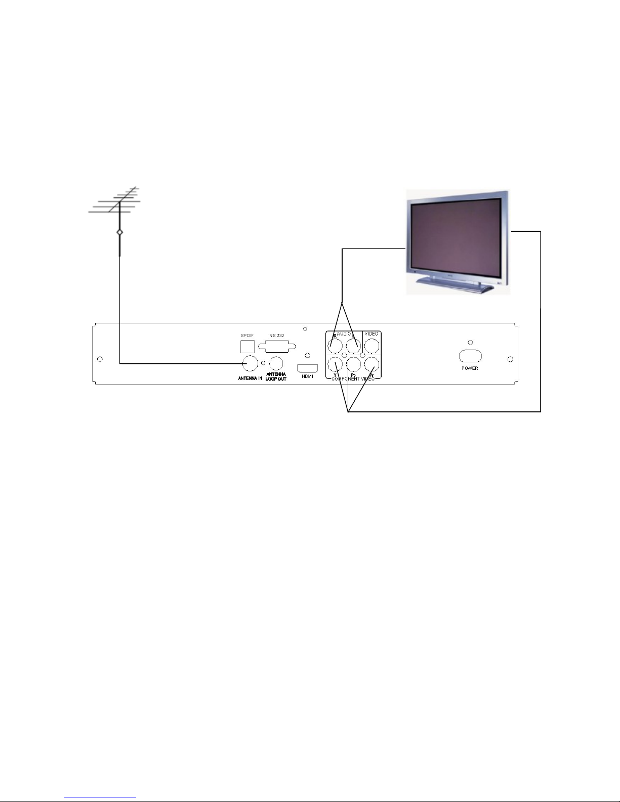
2. BASIC SET UP - COMPONENT VIDEO (RED, BLUE, GREEN)
.....................................................................................................................10
3. BASIC SET UP- HDMI.......................................................................11
4. BASIC SETUP. HOME THEATRE ...................................................12
REBOOT THE RECEIVER .............................................................................13
MAIN MENU ....................................................................................................14
I-BAR..................................................................................................................15
7-DAY ELECTRONIC PROGRAM GUIDE.................................................16
TV AND RADIO CHANNEL EDIT...............................................................17
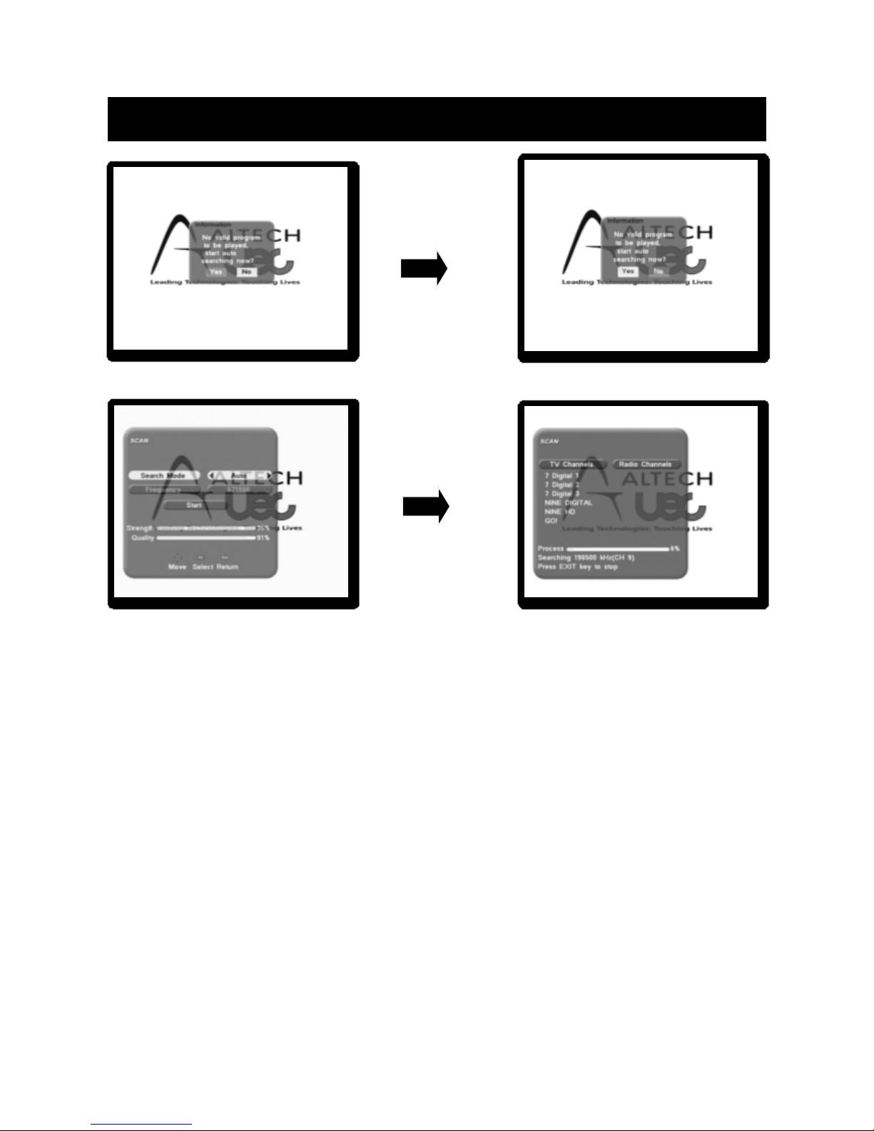
DIGITAL TV CHANNEL INSTALLATION .................................................17
TELEVISION SYSTEM SET UP ...................................................................19
TIME ZONE SETTING AND SYSTEM INFORMATION .........................20
FACTORY DEFAULT ......................................................................................21
VOLUME CONTROL AND AUDIO SELECTION .....................................22
SUBTITLES.......................................................................................................23
RADIO SERVICE & ASPECT RATIO ..........................................................24
TROUBLESHOOTING....................................................................................25
WARRANTY CERTIFICATE..........................................................................26

3
IMPORTANT SAFETY INFORMATION
1. Components inside your appliance are subject to high Voltage. Do not
ever open it, even after having removed the power cable. Generally
speaking, audio &video appliances are not connected to the earth, you
may then feel electric shocks (not dangerous) when touching both
appliances simultaneously (or one appliance and the antenna cable). We
advise to plug the appliances on the mains after having connected
everything.
2. Do not use solvent or detergent to clean up your terminal or remote
control. A dry cloth will perfectly remove dust.
3. Do not put the receiver close to other appliances. Choose a
well-ventilated place and do not put anything on the ventilation grid. Do
not ever put the receiver on another appliance; the overheating would
prematurely damage the components.
4. When there is storm, unplug all your audio-video appliances from the
mains: they could suffer damages not covered by manufacturer’s
warranty.
5. According to the obligations pursuant to EN 60065 standard, we draw
your attention onto the safety elements below. Do not block the
ventilation holes with paper, tablecloths, curtains, etc. A minimum
distance of 5cm is required around the appliance to ensure enough
ventilation.
6. Do not put naked fire sources on or close to the appliance, such as lit
candles. The appliance shall not be exposed to water dripping or splash.
Do not put things filled with water such as vases onto the appliance.
7. The remote control requires two AAA 1.5V batteries. Please follow the
polarity instructions written inside it. To respect environment and law,
please never throw out used batteries with household refuse.
8. In order to work properly, the appliance needs to be used according to
the instructions.
For further information you can email support@uec.com.au

4
GENERAL INFORMATION
The STB has functions which are possible, but not described in the manual.
We do not guarantee these functions and thus are not described.
As a matter of fact, functions considered not essential have been
deliberately removed from the document.
Follow the menus to program the terminal. In order to ease the reading of
the instructions below, the access to a particular menu shall be given as
follows:
MENU / menu / sub-menu.
For instance, when you read:
• Go to MENU / Scan/manual search
This means:
• Press MENU key to access the main menu.
• Press key ▼to choose the Scan menu and press OK.
• Press OK to confirm.
You will notice in the menu that the words written in bold in the manual
correspond to the ones on the TV screen.

5
QUICK START GUIDE
Your DT3900 once plugged in to your TV set and after you have selected
the appropriate TV input will display the first image as shown above.
Please ensure you have the aerial cable connected to the DT3900.
(SEE PAGE 9)
Please follow the prompt on the screen to tune your set top to available
digital TV signals.
The scanning process will take a few minutes and all available channels
will be loaded onto the set top.
Once finished you can exit from the screen and you will see pictures.

6
REMOTE
10-9. In standard mode, the numbered keys allow to
enter the channel number you wish to view. In
programming mode, they will allow you to enter
digits.
2STANDBY. Switches the receiver on and off
(standby).
3MENU. Press for main menu or to return to the
previous menu.
4LIST. Display the channel list.
5EXIT. to clear a function.
6EPG. Displays the Electronic Program Guide
(EPG).
7MUTE. Press to mute the sound. Press the key
again for sound.
8FAV. Short-cut to Favorites.
9+/-/▲/▼. Arrows to navigate menus and change
parameters. Also allows you to switch channels
and adjust volume.
10 TV/RAD. To switch the program between TV and
Radio.
11 INFO. To display the current program information.
12 AUDIO. Allows you to select an alternative audio
output (language, Dolby, digital).
13 CC. Select closed caption. (SUBTITLES)
14 OK. To execute an instruction and also lists
program in normal operating mode.

7
FRONT PANEL
1. To display the status of the receiver and program number.
2. 4. To adjust volume
3. 6. To change the channel
5. Menu entry
7. Standby button
8. Operation confirmation
REAR PANEL
1. Terrestrial aerial input
2. Interface, SPDIF output
3. D-sub connectors for software Upgrades only
4. Antenna loop output
5. HDMI output (high definition)
6. YUV outputs (analogue high definition)
7. Analogue audio output. Right/Left
8. Video signal output
9. Power plughole

8
USING THE SET TOP BOX
You will mostly only use the followings keys (the function of these keys is
explained in the previous paragraph):
• Key + /- to adjust the volume.
• Key ▼▲ to change channels.
• Key Mute to cut off the sound
• Numbered keys or OK for quick access to a channel.
• Key EPG to access the 7 day programme guide.
ADD NEW CHANNELS
If new channels are broadcasted, you can add them as follows: Menu /Scan
/ Automatic Search.
A factory reset (MENU / Settings / Factory settings may be a better
option as it will also remove channels.

9
CONNECTION
1. BASIC SET UP - COMP OSITE VIDEO
Uses the single Yellow RCA Video connector for Composite Video (CVBS)
with the Red and White RCA AUDIO R & L . All video outputs are active.
1. 1Prepare your equipment
Ensure that the power leads to both the TV set and the Set Top Box are
unplugged whilst making AV connections.
1.2. Connecting Video and Audio
Video
Connect the yellow CVBS Composite Video output from your receiver to
the Composite Video input of the TV
Audio
a) Connect the Red and White AUDIO L&R output from your receiver to
2 x RCA leads connect the other end of each RCA lead to the
corresponding Audio input connectors on your TV set.
1.3. Connect the antenna…
To the “ANTENNA IN” connection on the rear of your receiver.
1.4. Mains Power- Turn all your devices at the mains power & you are
ready to scan.

10
2. BASIC SET UP - COMPONENT VIDEO (red, blue, green)
For a basic component connection, use the Red Blue Green video and the
Red White audio connectors on the back of the receiver. The RCA leads
included with your receiver can assist.
All video outputs are active simultaneously.
2.1. Prepare your equipment
Ensure that the power leads to both the TV set and the Set Top Box are
unplugged whilst making AV connections.
2.2. Connecting Video and Audio
Video a) Connect one end of a 3 wire RCA lead to the Red, Green and Blue
Y, Pb, Pr RCA output connectors on the rear of the set top box.
b) Connect the other end of this cable to the corresponding RCA video
input connectors on your television or monitor.
Audio. c) Connect a 2 wire RCA lead to the Red and White AUDIO L&R
output connectors on the rear of the set top box. d) Connect the other end of
the cable to the corresponding audio input connectors on your TV set.
2.3. Connect the antenna…
To the “ANTENNA IN” connection on the back of your receiver.
2.4. Mains Power
Turn on your set top at the mains power & you are ready to scan.

11
3. BASIC SET UP- HDMI
Uses the HDMI connector on the back of the receiver to provide a complete
digital video and audio connection in one neat cable. A HDMI cable of
length to suit your purpose is required. All video outputs are active.
3.1. Prepare your equipment
Ensure the power leads to both display and receiver are unplugged whilst
making your AV connections. Your TV must have a HDMI input.
Check your Monitor has a HDMI input.
3.2. Connect the antenna…
to the “ANTENNA IN” socket on the rear of your receiver.
3.3. Mains Power
Turn on your set top at the mains power & you are ready to scan.
Video and Audio share the one HDMI cable

12
4. BASIC SETUP. HOME THEATRE
For this Set Up use your preferred video connection, the example below
shows video connection via YPbPr, you can use other methods from the
previous examples. You will also need an optical fiber cable for the audio.
All of video output modes are ready.
4.1 Prepare your equipment
Make sure that your TV has an YPbPr input.
Be sure the using amplifier has a SPIDF fiber input.
Ensure that the power leads to the TV, the Set Top Box and the amplifier
are unplugged before you commence the set up procedure.
4.2 Connecting Video and Audio
Video
Connect the YPbPr cords from the YPbPr output of the Set Top Box to the
YPbPr input of the TV.
Audio
a) Connect the fiber optic cable to the SPDIF connector on the rear of the set
top box.
b) Connect the other end of the fiber cable to the SPDIF input on an
Amplifier.

13
4.3 Connect the antenna
Connect the antenna lead to the ANTENNA IN connection on the rear of the
Set Top Box.
3.4 Connect the power
3.4.1 Plug the power lead of the receiver into the mains.
3.4.2 Connect the power to your monitor.
3.4.3 Link the power to the amplifier; you are now ready to get started.
REBOOT THE RECEIVER
Resetting to factory default can be useful if you have change some settings
and lost some functions. Resetting takes the receiver back to its original
configuration and you will lose all personalized functions (favorites,
parental lock, etc…). To avoid resetting the receiver accidentally, you are
required to enter a PIN CODE to authorize reset as follows:
• Menu / Settings / Factory Reset
• Press the red button to confirm.
• Enter your PIN CODE (4 digits –factory code is 0000).
• Wait a few seconds

14
MAIN MENU
The MAIN MENU allows you access to all set up controls in the set top
box.
Use the up and the down arrow key to navigate through the menu.
Press ok if you want to enter a section in the menu
Press exit if you want to exit from the menu
Pin code for installation is 0000

15
I-BAR
NOW - Press the INFO key on the remote to activate the basic information
bar. For more detailed information about this program, press the OK key
while the basic information bar is displayed.
LIST. The list button on the remote lists all available channels and the
arrow up/down button on the remote allow navigation through the list.
Once you have decided the channel to view press OK and your channel
will be displayed.

16
7-DAY ELECTRONIC PROGRAM GUIDE
1. A comprehensive Electronic Program Guide (EPG) is transmitted by
most broadcasters with details of Program Names, Times and
Descriptions that can exceed more than 7 days in advance. Please allow
some time for the EPG to load for each channel. If a channel has not been
viewed for a few days the information on that channel will be lost and
may need updating. (Picture 1)
2. You can access the EPG by pressing the EPG key on the Remote Control
Unit. (picture 1)
3. Use the UP/DOWN keys to select a channel. Press the OK key once to
display today’s program list. Present program is highlighted in Yellow.
Press the </> keys to see the program list for another day. Program detail
appears on screen in the top right hand frame. The UP/DOWN keys
reveal full program description where necessary. (picture 2)
(picture 1) (picture 2)

17
TV AND RADIO CHANNEL EDIT
Edit channel section in the main menu allows you to Delete, sort, move and
create a favourites list of all your channels.
Details on how to perform this is shown on the bottom of the page in the
Edit channel page in the menu.
Use the coloured
buttons on the remote
control to select the
task you want to perform.
The on screen prompts will
guide you through the
process.
Ensure that you save settings.
You can select your
favourite channel list via the FAV button on the remote
DIGITAL TV CHANNEL INSTALLATION
Select the scan function from the main menu
To perform an auto scan change search mode to auto or if you want to scan
for a specific channel use manual scan as shown above

18
SYSTEM CONFIGURATION
The system settings section in the main menu allows you to set parameters
that apply to your TV set up at home.
To access this from the main menu you need to key the pin number 0000.
Here you can change settings like Resolution, Time, Screen format and
Parental control.

19
TELEVISION SYSTEM SET UP
This product is designed to suit most types of Televisions. All outputs from
the DT3900 are active simultaneously. For use of Component video (Green,
Blue, Red) on older style Television sets you may need to reduce.
The resolution to 576i is as shown above. Please select confirm after
change.
The set top can also be configured for use on an old or a new widescreen
TV.
The aspect ratio 4:3 or 16:9 can be selected from the remote control key
[ASPECT].

20
TIME ZONE SETTING AND SYSTEM INFORMATION
The system setting menu allows you to set the time zone for the state you
are in. Please ensure this is set up otherwise incorrect time will be displayed
In this section you can also reduce the duration of your information bar and
set parental control, the default pin code for parental control is 0000.
During daylight saving in your state you may have turn daylight saving
time to on and your set top clock will move 1 hour ahead.
This section in the menu shows details of the Software version of the set
top.
In the event of future enhancement or software developments we may make
Software available on www.uec.com.au
Table of contents
Other AL Tech TV Receiver manuals