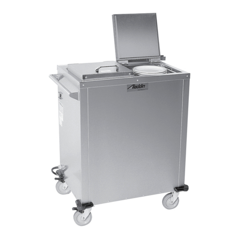
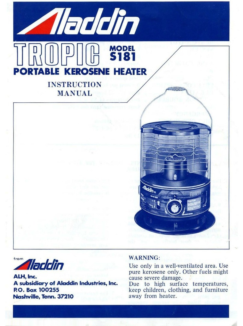
Aladdin Insul Plus DHO5 User manual

(
SYNERGETICS,,
INC.
SERVICE& INSTALLATIONMANUAL
Please read
this
manual
completely
before
attempting
to
install
or
operate this equipment!
Notl·ty carr,·er
of
dama~"'
'---ar'
_,,
----
--
--·-
immaa;-,,,ly
See
page
3
I
::J-•
:;,::;i,,_._..,.
;:::,
-_,...,,,
_,•..,1:=·
::..:, ,
...,
,C:,.., • •
C i~f
;:::;
.:.-
-.-..
'
:- .
~~
~-=-
-:·_-
,._.
..
~
.
-.
. -
-·
-.
-;-~_:-:'·.-
..
D;;
r;
,...E
10
wo6E
i1V:J
is
...
/11·
lnsul
PlusTM
base heaters
l

·CONTENTS
·•·
INTRODUCl10N..........-........-
••
-
...
-·-··--·
..
••
...........
__
3
RECErVING
AND
INSPECTING
................................................ 3
C'IST
ALLA
TION ..........................................................................3
OPERATION
-----
...............................
__
4
MAI:-."J"E.'iANCE
___
.................................
---··
4
ELECRICAL
WIRING
DIAGRA.\! ...... S
TROUBLESHOOTING
REFERENCE
CHART. ........ 6
ASSE.\ffiLY
ORA
WlNGS
DISPENSER
ASSE.\ffiLIES ..............
___
................ 7
OHOS......... 8
0006..
10
REPLACE.\IENT
PARTS
LISTS
DISPENSER
ASSE.\ffiLIES
_______
7
DH05
.9
DH06
................................
11
EQUIPMENT WARRA.'ffY .............................
15
01994
Th•
D•lfuld
CompanJ.
01994Aladdin Syn•rg•tia, Inc.
SPECIFICATIONS
'
l
MOOEL
I
NUMBER
I
LENGTH
WIDTH
HEIGHT
'
I
40.37
in
I 24.oo
in
1 40.37
in
DH05
!
102.6
cm
I
61.0
cm
l 102.6
cm
'
DH06'
30.75
in
:
'
78.1
cm
24.00
in
;
61.0
cm! 40.37
in
I
102.6
cm
!
;
DH05A
I 40.37
in
24.oo
in
1 40.37
in
102.6
cm
61.0
cm
i 102.6
cm
i 30.75
in
24.00
in
i 40.37
in
DH06A
f
78.1
cm
102.6
cm
61.0
cm
!
40.37
in
i
24.00
in
' 40.37
in
j
DH05E
• '
102.6
cm
i
61.0
cm' 102.6
cm
1
30.75
in
'
24.00
in
: 40.37
in
DH06E
•
78.1
cm:
61.0
cm
• 102.6
cm
INDEPENDENTTESTING
This
equipment
has
met
the
requm:mcnts
to
be
lined
by
the
foUowing
organizations:
Undctwriters•
Laboratories
-File #E64923
Canadian Standards A>,ocatioo -Ftle ~LR34J.J84-I
National
Sanitatioa
Foundatloo
-
standard
peadiag
VOLTAG&'
HERTl/
PHASE
208/60/1 l
20816011
i
240/60/1 I
240/60/1
240/50/1
i
24015011
I
AMPS
16.3
13.0
:
14.0 i
;
i
I
I
12.0 !
;
16.3
:
13.0
,
i
.VE\!A
i
SHIP
?WG
I
'NfJGHT
'
I
6·20P ;
6-20P
'
I
'
6-20P j
i
6-20P !
'
;
213lbs
95.9
kg
183
lbs
82.4
kg
213
lbs
95.9
kg
183
lbs
82.4
kg
213
lbs
95.9
kg
1831bs
82.4
kg
2
For
parts
and
service, call (800) 888-5426
Aladdin~
l

...
INTRODUCTION
The Aladdin" OHObase heaters discuued
in
this manual
aze
mobile, thctm~tatically coall'Olled. forced air coavectioa beared
dispea=
suitable for use willt Aladdin lruul-Plus™ wax-filled
bases.
RECEIVING
AND
INSPECTING THE EQUIPMENT
Even though
mOSt
"'!Uipment
is
shipped crated.
=c
should be
taken
during:
unloading
so
the
equipment
i.s
not damaged while
being
moved
into
the building.
Carefully check
for
any
visible signs
o(
damage
to
the
C3rtons
or
containers.
If
evidence
or
damage exists. the package should
be
ooc:ncd immediately and a joint inventory and ex.unination
of
the
cOotents should be made by you and
the
driver.
Concealed
damage
ff
a concealed loss or damage is discovered after you have
gi~n
the
carrier a clear delivery receipt. notify
the
c:anicr
in
writing
immediately
or
within
10
days
Crom
the delivery date.
If
you
phone the carrier.
you
must
follow
up
the
call
in
Ymtiag
to
protect
INSTALLATION
Electrical
connection
Refer to the spedfico.tions data on page
2.
the se:i.il tag. your local
code
or
crtc:
>iational E!ec:rical Code
to
be
sure the unit is
con-
~ectcd to the
prop!r
pow~r source. A protected circuit
o(
the
correct volta.ge and
a..-np::rage
must
be run for conn~ction
of
the
line
cord.
A
DANGER
F..,ery
unil
i.,;
fitted
with
a
~rounded
power
cord
and
mt1,;t
he
connected
to a
properly
ground rc\·t:ptaclL•. Each rcccptacl~
must
be
wiri:d
tu
a
dedicated
circuit
protected
by a
fu,l.
or
circuit
hrcukcr
rJt~·d ar
nut
mon•
th;.in
!IJ
amps.
The
units have
an
ON/OFF
switch on the
en<l
of
the unit ne:ir the
;ush
handle.
R:::1d
t."!e
;·oi!owing sections
of
the manual reg:uding
s<!~-up
and
op::ro.cion
~e:"0re
turning
i:he
unit
an.
your rights. You.can only improve your position
as
a claimant by
prompdy reporting such loss or damage. You should also retain
all
cartons
orcontainers, including packing material, until an
inspcctioa
bas
been
made
or
waived.
Filing
a claim
NotatioO
of
loss
or
damage
does not coostiru~ the filing
of
a claim.
You
should file
your
daim in
writing
W",th
tr.e
carrier
immedi-
ately!
Carriers will furnish the necessary form upon requesL You
should
also request an inspection. If a
claim
is filed by
phone.
always
follow
up
immediately
in writing.
A
DANGER
The
power
5'\itch
shl)uld
be
turned
to
OFF
and
the
unit
dlsconn~ctcd
from
the
po'4"?I"
sour::e whenever
performin~
_;en·ic~
or
maintenance
functions..
Setting
up
the
equipment
All
models arc equipped with a self-leveling
mechanism.
consisting
o(
two or three stainless steel dispenser rubes. Each
rube
is
equipped with a
properly
calibrated stainless steel
compression
spring which
supporu
the adjustable stainless steel c3JT'ier head.
T.,e entire mech.1nism is removable through the top to
faciliute
c!eo.ning
and service.
Forparts
and
service, call (800) 888-5426 3

OPERATION
Brief
overview
11w!.1e
uniu
are
duigned
to OJHrale in a t/,,efiMd tan{Hraturc
range providing addedsafetyfor the
OPf!Falor
andto the
basu.
The thermostat
it
not
adjw.stabk.
Once
the
unic
h.u
bcea
turned on. the
small
round
red light.
the
(an
motor
and the
heater
will
come
on.
Units
will be provided with
a rectangular
'service'
[jght located next
to
the
ON/Off
switch
indicating
any
thcrmosucic failure.
The
fan
motor
will
begin
to circulate the
heated
air
in and
around the bases in a convection process that promotes a quick and
even
heat
absorption.
Once
the :iir inside the
cabinet
has
reached
the desired
tempera•
tun:.
the
thermostat
will continue to
maintain
this temperature by
regulating the
power
to the heater.
The
fan will run
3.S
long as the
unit is
on.
Loading
Load each
rube
by
c:u-eiuJ!y
sucking the
b=
on the carrier head.
Always keep the load centered
on
the carrier head. Do not exceed
the recommended base capacities. Model OHOS can
hold
up
10
90
bases; model DH06
c:in
hold up
!O
60 bases.
MAINTENANCE
The
following maintenance procedures should be
perfonncd
regularly.
in
order
to
ke::p your
OHO
unit
working efficiently.
0 Tum the unit off and disconnect the plug
from
the
outlet. and allow the cabinet
to
cool. If your unit is equipped with a "twist
lock·' plug, tum the plug to the left
(counter-clockwise)
to
unlock it before
puHir.g it out. Never pull
on
the cord.
To
recocr.ect the plug
to
the "twist lock"
outlet. match
the
hooked blade
to
the
corcesponding slot, push the plug straight
in
until
it
is seated.
and
tum
to
the
right
(
cloci<'Nise)
to
lock.
'.?
Loosen
the
cap screws on the deck
holding clips. Pull elevator assembly up
and out and set it
on
a work surface. Two
perscr.s should perform this operation.
v'/ipe it down with a damp cloth.
'.! Clean out any debris inside the cabinet
and wipe
it
down with a damp cloth. If
nacassarJ. loosen the screws holding the
Power
Set
the
power switcb
!O
the
ON
position.
Make
sure the
covus
ar.
closed completely
10
insure
proper
heating operation.
Allow a minimum
of
75 minutes to properly beat the bases.
Dispensing
~-
Open.tors should always wear glo"·es
or
plate lifters when
handling
heoted bases.
DANGER
0
WEAR
Bases can be dispensed one suck
at
l time. thus
ensuring
optimal
he:it
31
"11
times.
Tht1e units
are
famished
with a
red
~ter
✓
ict
..
Ujhl
locaud
near
the
ON/OFF
switch. If
at
any
tu1U
during
rhe
operation
of
rhe
heaur.
thiJ
light COtrU!S
on.
itmeans there has !Men a
thermostat
failure
and
power
to
the
heating
elem.em
ha.s
bun
cut off.
TM
fan
may
remain in operarion
bur
the unit will
not
heat.
Notify
your
mainunanct
JUptr
✓
iJor
bejort
anemptin5
:o
operate
:mit
again.
perforated guard pa~el
and
lift
it
out of the
cabinet. Wipe down
the
area around the
fan and heater carefully
to
avoid damage,
then reassemble panel.
·~ Place each mechanism back inside the
cabinet. Tighten the cap
screws
on the
deck holding c!ip,
rr.ai<.ir.g
sure
the unrt is
cer:terad
:n
:r.e caCir:et c:ean the outside
of :he cabinet witl: a
--:-:i!d,
non~abrasive
soao·or
detergent
ar.d
warm
water.
A
comrr.ercial stainless s:ee!
c!eaner
can
also be used.
To
avoid scratching rhefinish. do nor
:.1.u
abrasive po...,·ders
or
scouring pads.
A
DANGER
Do
not
nc-am
or
pressure
dc::in
or
hose
down
tht.•
c::ihinct. Thi,;
could
dama;:e
the
i:quipmcnt
and
pos,ihl,:-·
i.::J.usc
an
clcct:-ic:JI
shuck
to
the
opcr:.i:o:-.
4 Forparts
and
service, call (800) 888-5426 l

ELECTRICAL WIRING DIAGRAM
205VOI.T5.
60HEKTZ.
SINGLE
PHASE
(NEMA
6-20P)
61.ACK
GREEN
0
•
SCR.."W
TERMINAL
QUICK
CONNEcr•
SINGJ_E
51"
ADE
a..r
QU~
CONNECT.
W7-
DOUBLE
SPADE
Q
WlRE
CONNECTOR
Forparts
and
service, call (800) 888-5426 5

TROUBLESHOOT/NG REFERENCECHART
S>WlllMS
Unit
does
not
operate,
and
no
lights
are
on
Unit
heats,
but
fan
does
not
operate
Unit
does
not
heat,
but
fan
operates
and
service
light
is
on
Base
temperature
is
too
low,
fan
operating
Base
temperature
is
too
high,
fan
operating
Cover
is
loose
Cabinet
does
not
roll
easily
I
l'R08,IJJI.£
=
1.
No
power
2.
Bad
power
switch
3.
Loose
wiring
1.
Defective
motor
2.
Jammed
or
loose
fan
blade
3.
Loose
wiring
1.
Defective
heating
element
2.
Open
high
limit
switch
3.
Loose
wiring
1.
Jammed
or
loose
fan
blade
2.
Cover
is
open
1.
Closed
thermostat
2.
Closed
high
limit
switch
\
Hinge
screws
are
missing
or
loose
I
;
1.
Debris
on
wheel
or
axle
I
2.
No
lubrication
I
St:tJ/Tl)N$
1.
Make
sure
plug
is
connected
and
SWitth
is
ON.
Check
for
power
to
the
receptacle.
2.
Replace
power
switch
3.
Check
and
secure
wiring
1.
Replace
motor
2.
Replace
or
tighten
blade
3.
Check
and
secure
wiring
1.
Replace
heating
element
2.
Replace
switch.
Check
for
causes
before
restarting
equipment
3.
Check
and
secure
wiring
1.
Replace
or
tighten
blade
2.
Close
cover
1.
Replace
thermostat
2.
Replace
high
limit
switch
!
Replace
er
tighten
screws
!
1.
Clean
out
debris
l
2.
Lubricate
axles
with
load-bearing
grease.
j
Lubricate
swivel
bearings
wrth
3O-weight
oil.
6 Forparts
and
service, call {800) 888-5426
Aladdin3
C

~~
DH05
DISPENSER
ASSEMBLY
AND
PARTS LIST
I
DESC11JPTTON
1
Dispensing
head
guides
2
Head
assembly
3
Spring
ret3iner
cllp
4
Cap
screw,
1/4-20
x
1/2,
hex
5
Cap
nut.
1/4-20
6
Deck
holding
cllp
7
earner
bat
8
Spring,
P062·0090-4540-73-SR
TUBE
Dl5PEN5ER
ASS£¼'3LY
#020-1153
OEJ..RELJ)
I
020-1152
004-8861
632-0017
932-1003
004-8862
004--0017
615-0008
·c_.
DH06
DISPENSER
ASSEMBLY
AND
PARTS LIST
1
1
2
3
4
5
6
7
8
i
TUBE
0I5P::~iS::R
IASSEMBLY
#020-1155
0€SCRIPT/ON
DELF:EUJ
I
Dispensing
head
guides
Head
assembly
020-1152
Spring
retainer
clip
004-8861
Cap
screw,
1/4-20
x
112,
hex
632-0017
Cap
nut,
1/4-20
932-1003
Deck
holding
clip
004-8863
earner
bar
004-0017
Spring,
PC62-1190-4540-73-SR
615-0008
For
parts
and
service, call (800) 888-5426
ALADDIN
I
Q7Y.
12
3
39699
12
16
16
39700
4
39658
6
39701
24
~C/Nf
O,f.
3
2
39699
3
10
10
39697
2
39698
4
39701
16
7

ASSEMBLYDIAGRAM-DH05/DH05A/DH05E
8
10
LiNER
r\55EM6LY
:020-1€8"-
!'
'I
i:
! • I
' '
' -'
!
,,--;,
..
i/
rz,?1
@e---.._
I'
I I
~!
--
@)
~/
@
:BC'fiCM
,Ji.55:'..\-t=i..
Y
,
::c-zo-·e€:
For
parts
and
seNice, call (800) 888-5426
j:!ASE AS5:)AaLY I
~020-1€35
1iCP ,-G5CM6L
'!
l~02G•'€03
Aladdin~

REPLACEMENTPARTSLIST-DHOS/DHOSAIDHOSE
OELF1EUJ
ALADDIN
-ITEMI DESCRIPTION
PARTI
PARTI
OTY.
Lid assembly 020-1658
28761
1
1 Bushing, nylon hinge pin
932-1107
29821
5-
2 Hinge, left-hand
004-8543
29418
3-
3 Hinge, right-hand
004-8544
29417
3
4 Screw, 1/4-20 x
.50
632-0017 12
5 Handle, lid
004-7378
3
6 Screw, 1/4"-20 x .75 932-1022 6
7 Handle, push/pull
020-1613
24639 1
8 Screw, 1/4"-20 x
1.00
632·0005
2
9 Washer, 1/4", external
lock
632-0207 2
10
Louvered panel, rear 004-7270 39636 1
11
Screw,
#10-24
x
.62
632·0037
3
12
Washer,
1110,
lock, inside star 932·1061 3
13
Cord w/plug, NEMA
6-20P,
240V,
6'
619-0079 29820 1
14 Switch, 30A, double pole 219-4212 29262 1
15 Light, service, 250V 619-0238 29261 1
16 Light, pilot, red, 112•,
250v
619-0237
29260
1
17
Motor, 208-230V/60Hz/singlephase 616-0017 24635 1
19
Switch, high limit, 265°F 619-0188
29183
2-
20 Thermostat, 230°F.
619-0189
29184
1 -
22
Screw,
116-32
x
37
932-1001 6
23
Nwt.
116·32,
hex lock
932·1010
6
24 Nut, hex, #8-32, S/S 632-0121 4
25
Washer, #10, shake proof 932·1061 4
26 Caster. 5•, swivel w/brake, polyolefin 623-0210 29264 2
r
27
Caster, 5°, rigid, polyolefin 623-0211
29263
2
' 28
Fan
wheel
616-0005
24636 1
29
Heater guard, perforated 004-0010 39392
30
Healing element,
208V/2600W
(std. &
"E"
models)
619·0218
24833
1
30
Heating element,
240V/2600W
("A" models) 619-0272 24832 1
31
Screw, 5/16"·18 x .75
632·0019
16
32 Screw, i/10-32 x .62 932·1091 3
33
Scc-,per,
wrap-around 623-0166 29647 10.5'
34 s~c-,cer insert, aluminum 605-0004 28736 10.5'
35
Screw,
1110-32
x 1.25 632-0006 24
36
Gas:«,I. lid, magnetic 670-0062 29561
3·
37
Screw.
118-32
x .50
932-1155
42
38
Harness, wiring 618-0001
29797
1
39
Pin
hinge. brass
323-4360
2
Resistor (50 Hertz models only) 619·0271
29977
l
For
parts
and
service, call {800) 888-5426 9

.-ASSEMBLY
DIAGRAM-DH06/DH06A/DH06E
10
I
t.JNE:~
A.55:'.MeLY ,
.
.:020-t679
l
~~
~'--l,.,0~ i 1! i /
, j
(zv
20
"l"X
~e
31
✓,~----~.
31
\·~
'
.-:-,;:~-:-=~=
!
5C".'7C\i
.
.i..55~.\tCL
'!
I
:.-:;-z-::;-!,&50
.,
'I
i~,::
; 1
For
parts
and
service, call (800) 888-5426
i
7'CP
ASS:~BL
'!
!=0'2('.>"680
(
l

.........
~
...
-,
...
_
......
-1
REPLACEMENTPARTS
LIST-DH06/DH06AIDH06E
DELFIELD ALADDIN
i~
ITEM#
DESCRIPTION
PART#
PART# QTY.
Lid assembly 020/1658 28761 1
1 Bushing, nylon hinge pin 932-1107 29821 4
2 Hinge, left-hand 004-8543 29418 2
3 Hinge, right-hand 004-8544 29417 2
4 Screw, 1/4-20 x .50 . 632-0017 8
5 Handle, lid 004-7378 2
6 Screw, 1/4
"-20 x .75 932-1022 4
7 Handle, push/pull 020-1613 24639 1
8 Screw, 114•.20 x 1.00 632-0005 2
9 Washer, 1/4•, extemal
lock
632-0207 2
10 Louvered panel, rear 004-7317 1
11
Sc:ew,
1#10-24
x .62 632-0037 2
12 Washer,
1#1
O,
lock, inside star 932-1061 2
13 Cord w/plug, NEMA 6-20P, 240V,_6' 619-0079 29820 1
14
Switch, 30A, double pole 219-4212 29262 1
15
Light, service, 250v 619-0238 29261 1
16 Light, pilot, red, 1/2', 250v 619-0237 29260 1
17
Motor, 208-230V/60Hz/single phase 616-0017 24635 1
19 Switch, high limit, 265°F 619-0188 29183 2
20 Thermostat, 230°F 619-0189 29184 1
22 Sc:ew, #6-32 x 37 932-1001 6
23 Nut. =6-32, hex leek 932-1010 6
24 Net.
Mex,
#8-32, SIS 632-0121 4
25 Washer, #10, shake proof 932-1061 4
26 Caster,
5',
swivel w/brake, polyolefin 623-0210 29264 2
(
27
Caster, 5", rigid, polyolefin 623-0211 29263 2
28 Fan wheel 616-0005 24636 1
29
Heater guard, perforated 004-0016 39394 1
30 Heating element. 208V/2600W (std. &
"E"
models) 619-0219 29266 1
30 Heating element, 240V/2600W ('A' models) 619-0273 28740
31
Sc:e'N. 5/16"·18 x .75 632-0019
15
32
Sc:e·N.
4i0•32
x .62 932-1091 3
33
Blir.~er.
wrap·around 623-0166 29647 8.75'
34
Burcoer insert, aluminum 605-0004 28736 8.75'
35 Scre'N. #10-32 x 1.25 632-0006 20
36 Gasket. lid, magnetic 670-0062 29561 2
37
Sc:ew, ~8-32 x
.SO
932-1155 28
38 Har~ess. wiring 618-0001 29797 1
39 Pin
~.inge.
brass 323-4360 2
Res:stcr (50 Hertz models only) 619-0271 299TT 1
l Forparts
and
service, call (800) 888-5426
11

. ·NOTES
(
12
For
parts
and
service, call(800) 888-5426
Aladdin~
l

-NOTES
.l
Forparts
and
serv;ce, call(800) 888-5426
13

··NOTES
14
Forparts
and
service, call (800) 888-5426
Aladdin®
L

-
.
(
l
EQUIPMENTWARRANTY
For a
period
of90
days (labo<)
and
one
year (parts).
Alad<tin
Synergetics warrants this equipment
to
the original buyer
to
be
free
from
defecu
in material and workmanship Ifwithin the
warrancy
period. a part is aclcnowledged by
Alad<tin
to be defective, all
obligations will bave been fully complied with
by
one
of
the
following methods:
I. Fumi.,hing replacement
part
F.O.B. factory
in
even exchange
for the rerurned part. m,ight prepaid.
2.
Fumi.,hing a
free
replacement part. F.O.B. factorr.
3. Receiving the defective
part.
ln,ight prepaid. repairing it and
returning
it
F.O.B. factory.
This W21m!C)' does notapply to
my
damage
in
tnnsit
or
resulting mim iasullatioa. DOl' does it apply
to
damage or
r~
resulting
mim
normal wear
and
tear, misuse. abuse,
~
alteration. It
become.s
void
ifdamage or failure
oc=,
as
a
.,!,';
of
unauthorized service or instillation'ofany
part
001
"'PPlied
i,,
the
manufacrurer
or Aladdin. This
warrancy
shall fintber 001 1
to
any
expenses.
rosses
orcoa.,cquential damages to
any
otl>er
>pp
property occurring as aresult
of
unauthorized service
or.pares_
Alteruioa. defacing or removal
of
the serial
nwnben
voids
this
warrancy.
Thi•
warrancy
is
oaly effective within the United States and
Canada.
For
parts andservice, call (800) 888-5426
This manual suits for next models
5
Table of contents
Other Aladdin Heater manuals
Popular Heater manuals by other brands

CONVECTAIR
CONVECTAIR DIVA 7647 Installation & operation instructions

Olimpia splendid
Olimpia splendid CALDO CRYSTAL Instructions for installation, use and maintenance

Vitek
Vitek VT-1703 Manual instruction

Verine
Verine Marcello NBFP00RP Installation, user and servicing instructions

IVT
IVT GFH-10ATD instruction manual

GHP Group
GHP Group Dyna-Glo RMC-FA40 user manual