Alamo Water R14-02 User manual
REVERSE OSMOSIS
INSTALLATION AND OPERATION MANUAL
R14-SERIES
ALAMO WATER REFINERS

Alamo Water Refiners, Inc.
13700 Hwy. 90 West
San Antonio, TX 78245
U.S.A. 210-677-8400
www.alamowater.com

IMPORTANT
Please read the entire manual before proceeding with the installation and startup:
Do not use where the water is microbiologically unsafe.
Always turn off the unit, shut off the feed water, and disconnect the electrical power when
working on the unit.
Never allow the pump to run dry.
Never start the pump with the reject valve closed.
Never allow the unit to freeze or operate with a feed water temperature above 100°F.
NOTES
Changes in operating variables are beyond the control Alamo Water Refiners, Inc. The end user
is responsible for the safe operation of this equipment. The suitability of the product water for
any specific application is the responsibility of the end user.
Successful long-term performance of a RO system depends on proper operation and maintenance
of the system. This includes the initial system startup and operational startups and shutdowns.
Preventing fouling or scaling of the membranes is not only a matter of system design, but also a
matter of proper operation. Record keeping and data normalization is required in order to know
the actual system performance and to enable corrective measures when necessary. Complete and
accurate records are also required in case of a system performance warranty claim.
Changes in the operating parameters of a RO system can be caused by changes in the feed water,
or can be a sign of trouble. Maintaining an operation and maintenance log is crucial in
diagnosing and preventing system problems. For your reference, a typical log sheet is included
in this manual.

TABLE OF CONTENTS
I. Introduction
A. Specifications
B. Overview
C. Pre-treatment
II. Controls, Indicators, and Components
A. Figure # 1 General System Drawing
B. Figure # 2 Package One Controller Drawing
C. Figure # 3 Package Two Controller Drawing
III. Operation
A. Installation
B. Plumbing Connections
C. Electrical Connections
D. Startup
E. Controllers
F. Operation and Maintenance Log
G. Trouble Shooting
IV. Replacement Parts List
V. Membrane Replacement
VI. Appendix
Flow Rate Guidelines
Temperature Correction Factors
Filmtec Technical Information - Cleaning and Disinfection of Filmtec RO Membranes

I. INTRODUCTION
The separation of dissolved solids and water using RO membranes is a pressure driven
temperature dependent process. The membrane material is designed to be as permeable to water
as possible while maintaining the ability to reject dissolved solids.
The main system design parameters require the following:
Internal flows across the membrane surface must be high enough to prevent settling of fine
suspended solids on the membrane surface.
The concentration of each dissolved ionic species must not exceed the limits of solubility
anywhere in the system.
Pre-treatment must be sufficient to eliminate chemicals that would attack the membrane
materials.

A. SPECIFICATIONS
R14-02 R14-03 R14-04 R14-05 R14-06
Productivity (Gallons per day / Gallons per minute)
Maximum production based on standard membranes and feed water of
25°C, SDI < 3, 1000 ppm TDS, and pH 8. Individual membrane
productivity may vary (± 15%).
3600 / 2.5 5400 / 3.75 7200 / 5.0 9000 / 6.25 10800 / 7.5
Quality (Typical Membrane Percent Rejection) Based on membrane
manufactures specifications, overall system percent rejection may be less. 98 % 98 % 98 % 98 % 98 %
Recovery without reject recycle 29 % 39 % 50 % 57 % 62 %
Recovery with reject recycle (adjustable) 50 % 50 % 75 % 75 % 75 %
Membrane Size 4 x 40 4 x 40 4 x 40 4 x 40 4 x 40
Number Of Membranes Per Vessel 1 1 1 1 1
Pressure Vessel Array 1:1 1:1:1 1:1:1:1 1:1:1:1:1 1:1:1:1:1:1
Number Of Membranes 2 3 4 5 6
Prefilter (System ships with one 5 micron cartridge) 20" BB 20" BB 20" BB 20" BB 20" BB
Feed Water Connection 1" NPT 1" NPT 1" NPT 1" NPT 1" NPT
Product Water Connection 3/4" NPT 3/4" NPT 3/4" NPT 3/4" NPT 3/4" NPT
Reject Water Connection 3/4" NPT 3/4" NPT 3/4" NPT 3/4" NPT 3/4" NPT
Feed Water Required
Feed water required will be less if reject recycle is used. 9 gpm 10 gpm 10 gpm 12 gpm 13 gpm
Feed Water Pressure (Minimum) 20 psi 20 psi 20 psi 20 psi 20 psi
Drain Required 9 gpm 10 gpm 10 gpm 12 gpm 12 gpm
Electrical Requirement
230 VAC, 3-ph, 60 Hz (Other voltages available) 15 amps 15 amps 15 amps 15 amps 15 amps
Multistage Centrifugal Pump 15 stages 15 stages 15 stages 18 stages 18 stages
TEFC Motor (Horse Power) 5 5 5 5 5
Dimensions L x W x H (Inches) 60 x 18 x 56 60 x 18 x 56 60 x 18 x 56 60 x 18 x 56 60 x 18 x 56
Shipping Weight (Estimated Pounds) 400 500 600 700 800
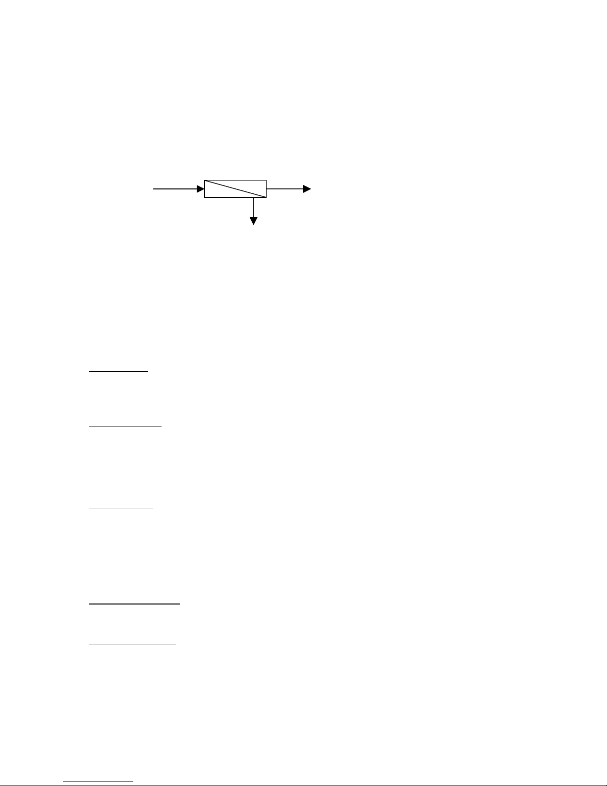
B. RO OVERVIEW
Reverse osmosis systems utilize semipermeable membrane elements to separate the feed
water into two streams. The pressurized feed water is separated into purified (product) water
and concentrate (reject) water. The impurities contained in the feed water are carried to drain
by the reject water.
RO Membrane
Feed Water Product Water
Reject Water
C. PRETREATMENT
The RO feed water must be pretreated in order to prevent membrane damage and/or fouling.
Proper pretreatment is essential for reliable operation of any RO system.
Pretreatment requirements vary depending on the nature of the feed water. Pretreatment
equipment is sold seperatly. The most common forms of pretreatment are described below.
Media Filter - Used to remove large suspended solids (sediment) from the feed water.
Backwashing the media removes the trapped particles. Backwash can be initiated by time or
differential pressure.
Water Softener - Used to remove calcium and magnesium from the feed water in order to
prevent hardness scaling. The potential for hardness scaling is predicted by the Langelier
Saturation Index (LSI). The LSI should be zero or negative throughout the unit unless
approved anti-scalents are used. Softening is the preferred method of controlling hardness
scale.
Carbon Filter - Used to remove chlorine and organics from the feed water. Free chlorine will
cause rapid irreversible damage to the membranes.
The residual free chlorine present in most municipal water supplies will damage the thin film
composite structure of the membranes used in this unit. Carbon filtration or sodium bisulfite
injection should be used to completely remove the free chlorine residual.
Chemical Injection - Typically used to feed antiscalant, coagulant, or bisulfite into the feed
water or to adjust the feed water pH.
Prefilter Cartridge - Used to remove smaller suspended solids and trap any particles that may
be generated by the other pretreatment. The cartridge(s) should be replaced when the
pressure drop across the housing increases 5 - 10 psig over the clean cartridge pressure drop.
The effect of suspended solids is measured by the silt density index (SDI) test. An SDI of
five (5) or less is specified by most membrane manufacturers and three (3) or less is

recommended.
Iron & Manganese - These foulants should be removed to less than 0.1 ppm. Special media
filters and/or chemical treatment is commonly used.
pH - The pH is often lowered to reduce the scaling potential.
Silica: Reported on the analysis as SiO2. Silica forms a coating on membrane surfaces when
the concentration exceeds its solubility. Additionally, the solubility is highly pH and
temperature dependent. Silica fouling can be prevented with chemical injection and/or
reducing the recovery.
II. CONTROLS, INDICATORS, and COMPONENTS (see figure 1)
A. Controller - Controls the operation of the system and displays the product water
quality. There are three controllers available. Controller # 1 has an on/off switch and
an input for tank level. Controller # 2 has an on/off switch, tank level input, low
pump suction pressure shutdown, and a product water TDS meter. Controller # 3 is
the CI1000 (shown).
B. Reject Control Valve - Controls the amount of reject flow. If the reject recycle option
is included, two reject control valves will be present.
C. Pump Discharge Valve - Used to throttle the pump.
D. Prefilter Pressure Gauges - Indicates the inlet and outlet pressure of the prefilter. The
difference between these two gauges is the prefilter differential pressure.
E. Pump Discharge Pressure Gauge - Indicates the pump discharge pressure.
F. Reject Pressure Gauge - Indicates the reject pressure.
G. Reject Flow Meter - Indicates the reject flow rate in gallons per minute (gpm). If the
reject recycle option is included, two reject flow meters will be present.
H. Product Flow Meter - Indicates the product flow rate in gallons per minute (gpm).
I. Prefilter Housing - Contains the RO prefilter.
J. Automatic Inlet Valve - Opens when pump is on and closes when the pump is off.
K. Low Pressure Switch - Sends a signal to the controller if the pump suction pressure is
low. Included only with controller option # 1 & 2.
L. RO Feed Pump - Pressurizes the RO feed water.
M. RO Membrane Vessels - Contains the RO membranes.
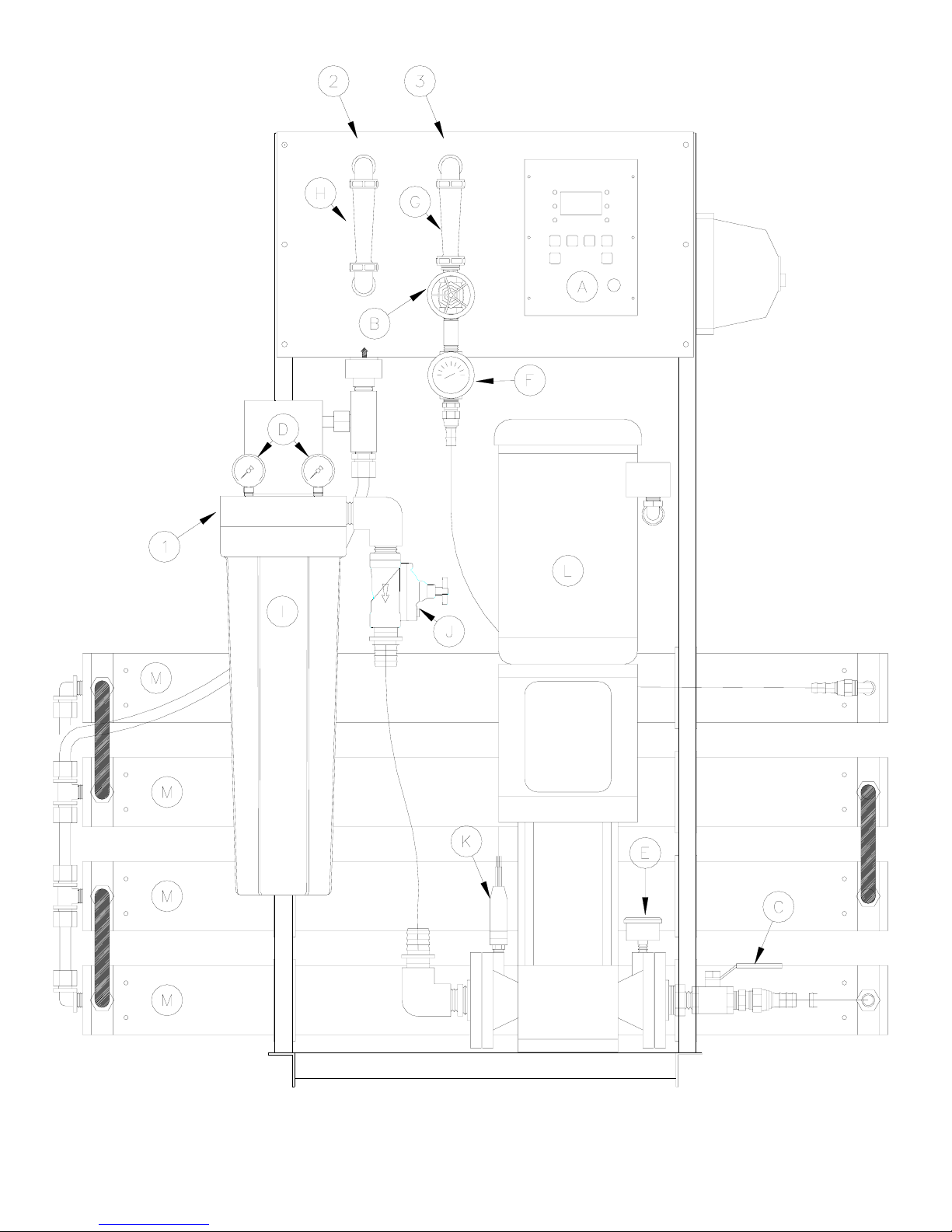
Figure 1
Separate motor starter
enclosure used only with
CI 1000 controller.

Figure 2
Controller Package One

Figure 3
Controller Package Two

III. OPERATION
A. INSTALLATION
1. The water supply should be sufficient to provide a minimum of 20 psig pressure at the
design feed flow.
2. Proper pretreatment must be determined and installed prior to the RO system.
3. A fused high voltage disconnect switch located within 10 feet of the unit is
recommended. This disconnect is not provided with the RO system.
4. Responsibility for meeting local electrical and plumbing codes lies with the owner /
operator.
5. Install indoors in an area protected from freezing. Space allowances for the removal of
the membranes from the pressure vessels should be provided. This system requires 42"
minimum clear space on each side.
B. PLUMBING CONNECTIONS
Note: It is the responsibility of the end user to ensure that the installation is done according to
local codes and regulations.
1. Connect the pretreated feed water line to the inlet side of the prefilter housing. (Figure #
1 item # 1) A feed water shutoff valve should be located within 10 feet of the system.
2. Temporarily connect the outlet of the product water flow meter to drain. (Figure # 1 item
# 2) The product water line should never be restricted. Membrane and/or system damage
may occur if the product line is blocked.
3. Connect the outlet of the reject water flow meter to a drain. (Figure # 1 item # 3) The
reject drain line should never be restricted. Membrane and/or system damage may occur
if the reject drain line is blocked. An air gap must be located between the end of the drain
line and the drain. The use of a standpipe or other open drain satisfies most state and local
codes and allows for visual inspection and sampling.
C. ELECTRICAL
Note: It is the responsibility of the end user to ensure that the installation is done according to
local codes and regulations.
1. A safety switch or fused disconnect should be installed within 10 feet of the system.
2. Verify that the disconnect switch is de-energized using a voltmeter.
3. Connect the outlet of the disconnect switch to the terminals on the motor starter (Figure #
2, or 3). Attach the power supply ground to the chassis ground. It will be necessary to
drill a hole in the enclosure and install a water tight strain relief or conduit connector.
The hole size and location must be determined by the installer. Check the pump motor
nameplate for the amperage draw at various voltages to determine the wire size required.

4. Do not apply power to the RO unit at this time.
D. STARTUP
1. Verify that the pretreatment equipment is installed and working properly. Verify that no free
chlorine is present in the feed water.
2. Verify that the on/off switch is in the off position.
3. Verify that the pump discharge valve (Figure # 1 item C) is open.
4. Install a 20" five micron filter cartridge in the prefilter housing. (Figure #1 item I)
5. Open the reject control valve completely (Figure # 1 item B) by turning it counterclockwise.
Close the reject recycle control valve completely if the reject recycle option is included.
6. Open the feed water shutoff valve installed in step III-B-1 above.
7. Manually open the inlet solenoid valve (figure #1 item J) by turning the white lever located
near the valve outlet.
8. Water will flow through the system and to drain through the reject flow meter (figure # 1
item G).
9. Manually close the inlet solenoid valve after the air has been purged from the system, or after
10 minutes, whichever occurs first.
10. Close the pump discharge valve half way. (Figure # 1 item C)
11. Engage the safety switch or disconnect (installed in step III-C-1 above) to apply electrical
power to the RO system.
12. Move the controller on/off switch to the on position. Move the switch back to the off
position after the pump starts and look at the motor fan as the pump stops to determine if the
pump rotation is correct. If the CI 1000 Controller is included (controller option # 3), put the
key switch in the on position and press the start / stop button to turn the pump on and off.
There is a 10 second delay before the pump starts. See the controller section for more
details. The fan should rotate in a counterclockwise direction when viewed from the top.
Continue with the startup if the pump is rotating in the proper direction. If the pump is
rotating backwards, change the rotation by disconnecting the power and reversing any two of
the wires on the power inlet. (Figure #2 item #1) Verify proper pump rotation before
continuing.
13. Turn the system on.
14. Adjust the reject control valve(s) (figure # 1 item B) and the pump discharge valve (Figure #
1 item C) until the desired flows are achieved. Closing the reject valve increases the product
flow and decreases the reject flow. Opening the pump discharge valve increases both the
reject flow and the product flow. See the flow rate guidelines and temperature correction
table in the appendix to determine the flow rates for different operating temperatures.
15. Allow the product water to flow to drain for 30 minutes.
16. Turn off the system and connect the product line to the point of use. (Figure # 1 item # 2)
The product water line should never be restricted. Membrane and/or system damage may
occur if the product line is blocked.
17. Restart the system and record the initial operating data using the log sheet in the next section.
Note: See the controller section of this manual for more installation and operation
information

E. Controllers
Two controller options are available.
Controller option # 1 is a basic controller with an on / off switch, low pressure, tank level, and
pretreatment interlock (see figure # 2).
Automatic low pressure reset
If the unit shuts down due to low pressure, a red light on the front of the controller will
illuminate. The controller will automatically restart the unit after a user selected time delay. The
user selects the delay time by positioning a jumper cap inside the controller (see attached
drawing).
Tank Level / Pretreatment Indicator
If the unit shuts down due to a high product tank level or pretreatment interlock, an amber lamp
will illuminate. The lamp will turn off and the unit will restart when the condition clears. The
same lamp is used for both tank level and pretreatment interlock.
Controller operation
1. When the power switch is turned on, the pump will run as long as the circuit between the
tank level terminals and the interlock terminals are closed, and the low pressure switch
contacts are open.
2. To install a tank level switch, remove the jumper wire from the terminal strip and connect the
level switch to the terminals. The RO pump and inlet valve will turn on when the level
switch contacts are closed (tank not full), and turn off if the level switch contacts open (tank
full).
3. To install a pretreatment interlock, remove the jumper wire from the terminal strip and
connect the normally closed pretreatment switch contacts to the terminals. The RO pump
and inlet valve will turn on when the switch contacts are closed, and turn off if the switch
contacts open.
4. If the low-pressure contacts close continuously for five (5) seconds, the RO pump and inlet
valve will turn off and the low pressure light will illuminate. The controller will
automatically restart the unit after the user selected time delay. Turning the controller off
then back on will manually reset a low pressure shutdown.
5. Note: Use the plastic lever to push the terminal strip contacts open. Insert the bare end of the wire into
the terminal and release the lever. The lever can be moved from one terminal to another as needed. One lever
is included with each controller.

Controller option # 2 is the CI 1000. This is a microprocessor based controller with a product
water conductivity meter. A separate manual for this controller begins on the next page.
The autoflush option is available with both controllers. On controllers # 1, the flush valve is
preset to open for 2 minutes every time the pump starts and 2 minutes every hour. On controller
#2, the flush times are user programmable. (See the following CI1000 information.)

REVERSE OSMOSIS CONTROLLER
OPERATION MANUAL
Model # CI-1000
ALAMO WATER REFINERS

TABLE OF CONTENTS
I. Introduction
A. Features
B. Specifications
C. Outputs
D. Inputs
E. Mode Descriptions
F. Controls
G. Indicators
II. Operation
A. Contrast Adjustment
B. Operation Screen
C. Configuration Screen
D. Timer Screen
E. Calibration Screen
F. Pop-Up Screens
III. Service and Maintenance
A. Troubleshooting
IV. Drawings
Figure 1 Front View
Figure 2 Electrical Connections

I. INTRODUCTION
The 3501 Reverse Osmosis Controller is designed to control and monitor the operating
parameters of a reverse osmosis water purification system. Information is displayed on a
back-lit liquid crystal display, and on individual light-emitting diodes (LEDs). Functions
and controls are operated through snap-dome switches (see Figure 1).
A. Features
Temperature Compensated Conductivity Monitor
Water Temperature Monitor
Three Modes of Operation: Stand-by, Tank Feed, and Direct Feed
Pretreatment Interlock
Tank Full Shutdown
Inlet Valve Control
Pump Control
Low Feed Pressure Sensing with Automatic Reset
Autoflush with Adjustable Flush Time
Diverter Valve Output
B. Specifications
Power Requirements: The controller can operate with a power source of 115 or
230 VAC single phase. A multi-function power inlet is used to select the proper
input voltage.
Fuse: 1 amp 250 volt slow blow, located inside the power inlet receptacle.
Environment: The controller can operate at a temperature from 0° to 60° C (32° to
140° F). Relative humidity must not exceed 95 percent.
Conductivity Monitor: The conductivity monitor measures the product water
quality and displays this information in micro-mhos/cm. The display is
temperature compensated to 25° C (770 F).

C. Outputs
Inlet Solenoid: A 24 VAC output is provided to power the inlet solenoid. This
output always energizes 12 seconds before the pump turns on, and de-energizes
12 seconds after the pump turns off.
Flush Valve: A 24 VAC output is provided to power the optional reject solenoid
valve. This output will energize during the flush cycle. This is an optional
accessory.
Motor Starter: A 24 VAC output is included to provide controlled pump
operation. This output powers the coil of the magnetic starter relay. This output
is energized depending on other operating parameters.
Diverter Valve: A 24 VAC output energizes when the product water quality is
below the setpoint. The valve is not included with the system. This output is
intended to power a relay or some other low current device. The maximum
current available is one ampere.
D. Inputs
WARNING: All the inputs described below are dry contacts. Do not apply voltage to
these contacts or permanent damage to the controller will result.
Conductivity Probe: There are four inputs for the conductivity probe, two for the
thermistor and two for the conductivity. Only probes with a cell constant of 1.0
and a thermistor with a nominal resistance value of 20K at 25' C will work with
this controller.
Low Pressure Switch: This is a dry contact that signals the system to shut down if
the pump suction pressure falls below the desired value. This is a normally open
contact. When a circuit is not complete between the two terminals, the system
will operate. If contact is made between the two terminals, the system will shut
down. The LCD display and a LED will indicate when the system is shut down
due to low pressure. The controller can be programmed to automatically restart.
This is described in Section III, Operation.
Tank Level: This is a dry contact that signals the system to shut down when the
storage tank is full. This contact is normally closed. When a circuit is complete
between the two terminals the system will operate. If contact is broken between
the two terminals, the system will shut down if it is operating in the tank feed
mode. A LED will indicate when the tank is full. The system will restart itself
when the contact is closed. The switch for this function in not provided with the
controller.

Pretreatment Interlock: This is a dry contact that signals the system to shut down
when a pretreatment device is not functioning, or regenerating. This could be
used on a water softener, multi media filter, chemical feed pump, differential
pressure switch, etc. This contact is normally open. When a circuit is not
complete between the two terminals the system will operate. If the contact is
closed the system will shut down. A LED will indicate when the system is shut
down due to pretreatment interlock. The system will restart itself when the
contact is opened.
E. Mode Descriptions
The stand-by mode is intended to place the system in a temporary non-operational
mode. When the system is placed in this mode it will operate for the amount of
time set for the flush cycle. If the flush time is set for zero the system will operate
for one minute. After this cycle is complete the pump will turn off and the inlet
valve will close. The system will repeat this cycle once every hour. When the
system is flushing, the amount of time remaining in the flush cycle will be
indicated on the last line of the display. When the system is idle, the amount of
time remaining until the next flush will be indicated. When the pump is running,
the reject valve and diverter valve outputs are energized.
The tank feed mode is intended to be used when the system is feeding a storage
tank. When in this mode the system will shut down when the tank level switch
(not provided) has an open contact. The flush cycle is also enabled in this mode.
If the autoflush option has been included on the system, the controller will
activate the flush cycle when the system is turned on and once every hour. When
the system is flushing, the amount of time remaining in the flush cycle will be
indicated on the last line of the display. When the system is not flushing the
amount of time until the next flush will be indicated. The system will still flush
every hour even if the tank is full. During a full tank condition the system is
essentially in standby. When the system is flushing, the diverter valve output is
energized. If the flush time is set for zero the system will not flush when the tank
is full.
The direct feed mode is intended to be used when the system is feeding a
distribution loop or another piece of equipment. In this mode the system will not
flush and the tank level switch is disregarded. When the system is in this mode,
the total number of hours the system has been operated will be indicated on the
last line of the display.
F. Controls (see figure 1)
NOTE: Refer to Section III, Operation for detailed instructions on operating the controls .
Start / Stop Button: This button turns the system on and off.
This manual suits for next models
4
Table of contents
Popular Water Filtration System manuals by other brands

Reo-Pure
Reo-Pure EC9052545 Installation, operation and maintanance manual

Watts
Watts PWRO4ZRO Pure Water Installation, operation and maintenance manual

Spirax Sarco
Spirax Sarco MPC1 Installation and maintenance instructions

Aquasana
Aquasana OptimH2O AQ-RO-3 owner's manual

Philips
Philips AWP3753 user manual

Young Lin
Young Lin aquaMAX-Basic 360 Series manual

Fumex
Fumex Movex OF 1000 manual

Perrin & Rowe
Perrin & Rowe UKIT1570LS installation instructions

Grunbeck
Grunbeck GENO-UV 60 S Operation manual

GOK
GOK GS Pro-Fi 3 Assembly and operating manual

Sartorius
Sartorius Arium Comfort I H2O-I Series operating instructions

Parker
Parker 660R-RAC Series installation guide


