ALAN Electronics Nautico User manual

Page 1 of 16
Nautico
Synthesizedmarine VHF Transceiver
OWNER’S MANUAL
ALAN Electronics GmbH

Page 2 of 16
Contents
1INTRODUCTION........................................................................................................................ 3
2FIRST AND FOREMOST… SAFETY!............................................................................................ 4
2.1 Symbols used ................................................................................................................................4
2.2 Warning..........................................................................................................................................4
2.3 Assistance .....................................................................................................................................4
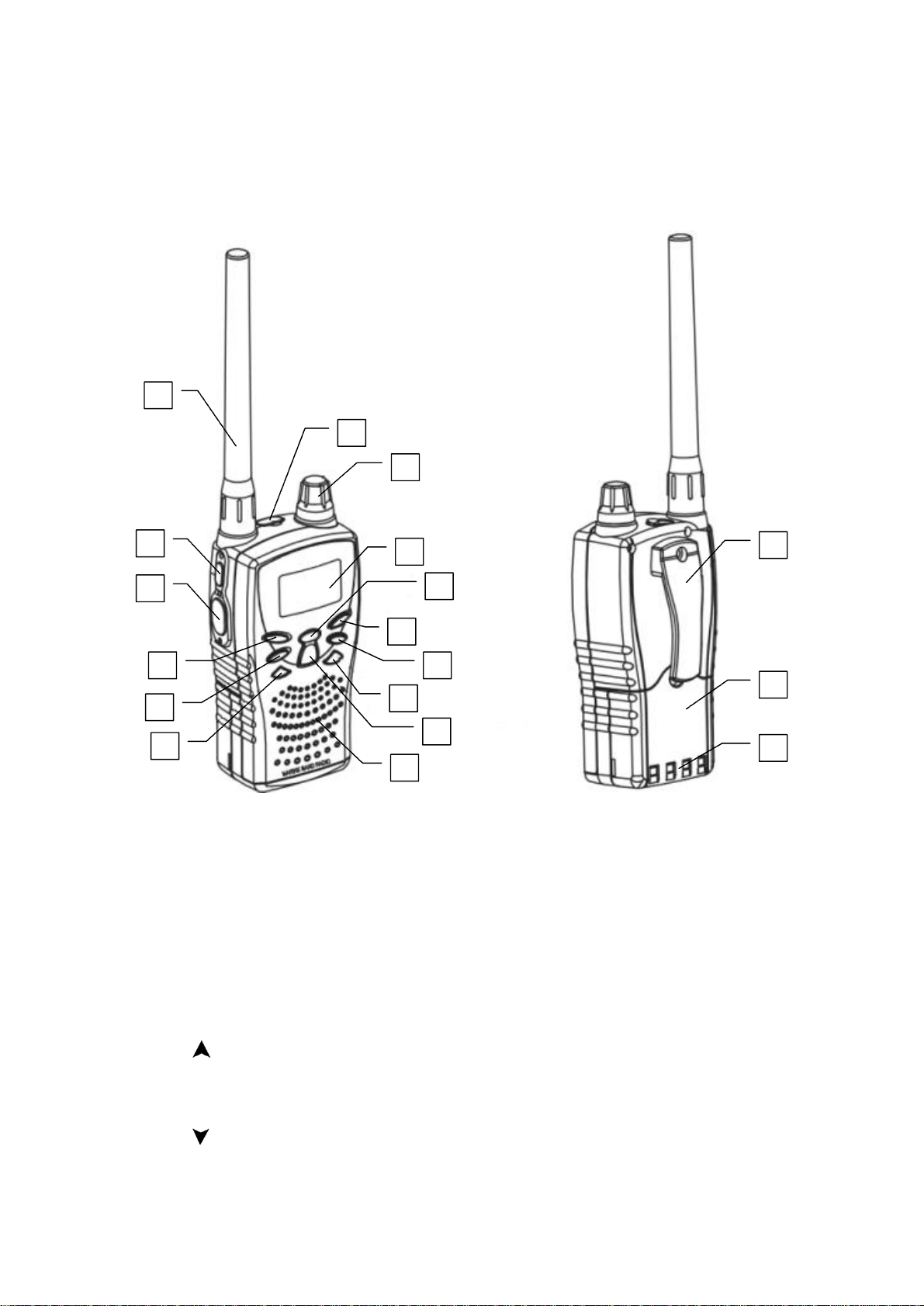
3DESCRIPTION OF THE PARTS.................................................................................................... 5
3.1 Description ofthe parts andcommands........................................................................................5
3.2 Displaysymbols.............................................................................................................................6
4PREPARATION......................................................................................................................... 7
4.1 Recharging the batterypack..........................................................................................................7
4.2 Memoryeffect ofthe rechargeable batteries.................................................................................7
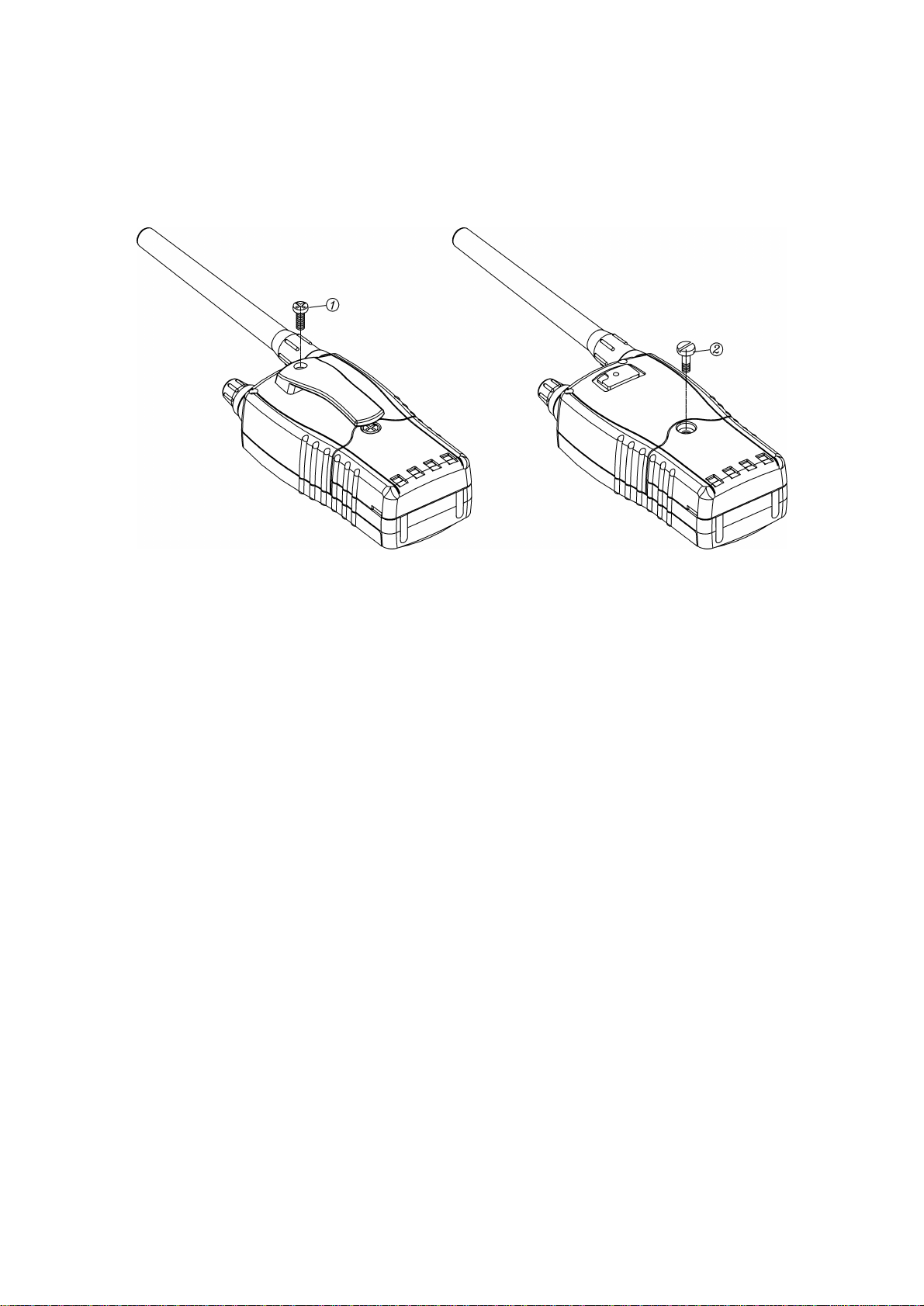
4.3 Removal/attachment ofthe beltclip ..............................................................................................8
4.4 Removal/attachment ofthe batterypack.......................................................................................8
4.4.a Removal ............................................................................................................................................8
4.4.b Attachment ........................................................................................................................................8
5BASIC OPERATIONS................................................................................................................. 9
5.1 Switching on/off .............................................................................................................................9
5.2 Volume regulation..........................................................................................................................9
5.3 Squelch regulation.........................................................................................................................9
5.4 MONI (monitor) button...................................................................................................................9
5.5 Channel selection..........................................................................................................................9
5.6 Transmission and reception...........................................................................................................9
5.7 Select high and lowtransmission power .......................................................................................9
5.8 Lighting the display......................................................................................................................10
5.9 Keypad lock .................................................................................................................................10
5.10 Programming the CALL channel .................................................................................................10
6SCANNING FUNCTIONS........................................................................................................... 11
6.1 All channel scanning....................................................................................................................11
6.1.a Skipping channels in scanning ........................................................................................................11
6.2 Dual Watch and TripleWatch......................................................................................................11
6.2.a Selecting Dual or Triple Watch........................................................................................................11
6.2.b Activating Dual/Triple Watch............................................................................................................11
6.3 Memorychannels ........................................................................................................................12
6.3.a Using the memories.........................................................................................................................12
6.3.b Programming the memory channels................................................................................................12
6.3.c Recalling memory channels.............................................................................................................12
6.3.d Scanning memory channels ............................................................................................................12
7TROUBLESHOOTING .............................................................................................................. 13
7.1.a Reset...............................................................................................................................................13
7.1.b Table of solutions ............................................................................................................................13
8TECHNICAL SPECIFICATIONS.................................................................................................. 14
8.1 Transmitter...................................................................................................................................14
8.2 Receiver.......................................................................................................................................14
9TABLE OF FREQUENCIES........................................................................................................ 15

Page 3 of 16
1 INTRODUCTION
Congratulations!Your Nautico handheld transceiver is provided with all of the main characteristics of quality, robustness
and reliability that the mostadvanced technology can offer;it can moreover, be immersed to adepth of 1meterfor 30
minutes. Nautico letsyou transmit and receive on all international channels included in the marine VHF band in full
security, as established by the International Telecommunications Union (ITU). This transceiver consistsof high quality
electronic componentsand conforms to the “JIS7” specifications and commercial standards guaranteeing clear,reliable
communication, and many years of perfect functionality. Nautico is controlled by amicroprocessor that allowsyou to
obtain advanced characteristics and services. The microprocessornotonly controls the tuning ofthe marine band, but
also advanced functions such as Dual and Triple Watch, memory channels and much more.
These are the main characteristics of your transceiver:
• PLL (Phase Locked Loop) synthesizer circuit – allows precise and stable channel selection.
• Backlighted LCD display –constantly indicates the parameters and settings programmed on the unit, even in
places with little ambient light.
• Squelch Regulation – in the pauses between transmissions, it eliminates irritating background noise also reducing
power consumption when receiving.
• Channel 16 recall button – allows instant access to channel 16 (the universal marine channel that is used most
frequently, also as the emergency channel).
• CALL button – lets you quickly recall your favorite channel.
• High/low power selector – allows you to save energy by reducing transmission power in short distance
communications.
• Keypad lock – locks the keys to avoid accidental programming.
• Batteryweak indicator – it appears when the battery pack is getting discharged.
• Desktop charger as standard – lets you easily recharge the battery pack, separately or installed in your
transceiver.
• Speaker and microphone jacks – through these sockets you can connect suitable external devices (headphones,
microphone/speakeretc.) for easieruse, above all in noisy environments.
• Dual and Triple Watch – allowyou to monitor channel 16 while listening to another synthesized channel (Dual
watch) and do the same with the CALL channel (Triple Watch)
• Scanning: automatically searches for the signals in the marine band.
• 10 memorychannels – you can store the 10 channels that you use most, recalling them in the blink of an eye and
also carry out the scanning process.
2 Note:the manufacturer,in constantly trying to improve the product, reserves the rightto change features without
any notice in advance.

Page 4 of 16
2 FIRST AND FOREMOST… SAFETY!
2.1 Symbols used
For quick and rational reading wehave used symbols tohighlight areas that need your maximum attention, or offer
practical advice or simple information.
! Notes like these,marked with an exclamation mark,highlight avery important description regarding
technical interventions, dangerous conditions, safety warnings, prudent advice and/or very important
information. Ignoring these could cause serious problems and/or damage and/or personal injury.
2 Notes like these, labeled with a memo note, constitute important practical advice that wesuggest following to obtain
the mostfrom the unit.
2.2 Warning
! AVOID TRANSMITTING WHEN THE ANTENNAIS NOT CONNECTED – even though the unit is protected, it
can seriously damage the power stages of transmission.
! Keep the antenna at least2,5 cm from your head and body when transmitting and do not use your
transceiver if the antenna is damaged.
! Do not hold the unitby its antenna! Itis very delicateand important for the correct functioning of the
device.
! PAY ATTENTION TO ATMOSPHERIC CONDITIONS- even though Nautico isdesigned to operatein the most
severe conditions, try not to expose it to excessively humid, dustyenvironmentsand to temperatures
outside the range of -20 to +50°C°. Above all avoid exposure to direct sunlight.
! AVOID EXCESSIVE IMPACTS AND VIBRATIONS, theunit is built to support impacts and vibrations,
provided that they are in the norm of any other electronic device.
! Do not use this device and/or change the batteries in potentiallyexplosive atmospheres. One singlespark
could cause an explosion.
! BATTERIES – Observe all the precautions on how to use the batteries described in chap. 4.1.
! DO NOT OPEN THE RADIO FOR ANY REASON, the precise mechanism and electrics ofwhich the unit is
composed require experience and equipment;for the same reason the radio should absolutely not be
readjusted, as it has already been calibrated in the factory to provide the maximum service. The opening of
the transceiver by un-authorized personnel will automatically invalidate the guarantee.
! Do not use alcohol, solventsor abrasive materials to clean the unit. Only use soft and slightly damp cloths.
For tougher dirty use a mild detergent.
! Your Nautico handheld marine transceiver incorporates aradio transmitter. Be aware that, when you press
the PTT button,you are radiating radio frequency signals (RF).
2.3 Assistance
Weadvise you to write the serial number of your transceiver in the space below.You will find this number on the back of
the transceiver. This will be needed in case of assistance and/or loss and/or theft of the unit.
Serial number_______________________

Page 5 of 16
3 DESCRIPTION OF THE PARTS
3.1 Description of the parts and commands
Make reference to the following images to localize the various parts of the unit and familiarize yourself with them:
1) Antenna – needed to receive and transmit radio signals
2) MONI (monitor) button – temporarily excludes squelch to receive even extremely weak signals
3) PTT (press to talk) button – pressing this button accesses transmission from the equipment
4) MEMO/M.PRG button– recalls and stores the most used marine channels
5) SCAN/DUAL button – ifheld down, it activates channel scanning/if pressed briefly, itactivates Dual or Triple
Watch
6) CALL button – recalls the preferred CALL channel from the memory
7) Speaker/Microphone sockets (protected) –allowconnection to external devices (headphones, microphones
etc.)
8) VOLUME control – switches the unit on/off and regulates the audio volume when receiving
9) LCD Display – the LCD (liquid crystal)display constantly indicates the operating state of the device and functions
used
10) CH/SQL/ button–used to move the tuning toward the higher marine channels and increase the squelch level
11) LOCK/LIGHT button– temporarily locks the keys/activates the display’s backlight
12) HI/LO/BAND button –selects lowor high transmission power, holding down the MONI button.
13) Button 16 – used to instantly recall channel 16
14) CH/SQL/ button - used to move the tuning toward the lower marine channels and reduce the squelch level
15) Integrated speaker/microphone - the transmission microphone and reception speaker are located here
16) Belt clip – Used to easily attach the unit to your belt during transportation
1
2
3
4
5
6
8
7
10
11
14
13
12
15
16
17
18
9

Page 6 of 16
17) Rechargeable batterypack – supplies power to the handheld transceiver
18) Batterypack charging contacts – used to connect to the charger supplied
3.2 Displaysymbols
Your marine transceiver uses an LCD (liquid crystal display)to keep you constantly informed of its operating state. The
following symbols and parameters may appear from time to time:
A) FUNC: appears when the “Function” mode is activated (hold down the MONI button).
B) TRI: the transceiver is carrying out the Triple Watch.
C) SCAN: the unit is scanning channels.
D) L(Lockout): indicates that the currently selected channel is skipped in the scanning.
E) MEMO: indicates that you are using your favorite memory channels.
F) These two small digits indicate the memory channel selected,or SL during squelch regulation.
G) The battery symbol lets you knowthat the battery pack is running low.
H) The key symbol indicates that the keypad lock is activated.
I) INT: clarifies that the selected channels are international.
J) These two large digits indicate the marine channel currently selected, or the squelch level during regulation.
K) LO (Low): indicates that you have selected lowtransmission power.
L) TX: appears when you are transmitting (PTT button pressed).
M) CALL: indicates thatyou are using the priority CALL channel.
N) BUSY (channel busy): appears on the display when the transceiver is receiving a signal.
O) DUAL: the transceiver is carrying outthe Dual Watch.

Page 7 of 16
4 PREPARATION
Before using your transceiver, you must be certain that the package includes:
• Transceiver
• 12 VDC Ni-MH rechargeable battery pack
• AC charger cradle complete with power cable
• Antenna
• Belt clip
• User’s manual
If there is something missing or damaged, please contact your supplier immediately.
2 Note.According to the version, the belt clip and rechargeable battery pack may already be installed in the
transceiver
Before going any further,be certain that:
• The 12VDC Ni-MH battery pack supplied is attached to the unit. If itisn’t,please make reference to par. 4.4.
• The antenna is connected, by means ofthe appropriate SMA connection.
• The unit is switched off.
4.1 Recharging the batterypack
The battery pack supplied is a 12V Ni-MHtype and can be charged both when it is attached to the transceiver, and when
it’s separated from the unit; 14 -15 hours are necessary to recharge it completely.
To recharge the battery pack:
1) Insertthe plug on the charger cable into a AC mains supply power socket and the other end into the socket found
on the charger cradle.
2) Place the battery pack or the transceiver firmly into the cradle: charging will then start and will be indicated by a
glowing LED light.
3) When charging has finished, remove the battery pack or transceiver from the cradle and disconnect the charger
cable from the AC mains supply power socket.
! Warning! Do not overcharge the batteries! When the battery pack is completely charged, the charging
process doesn’t stop automatically. Thereforedo not forget to extract the battery pack or transceiver from
the charger as soon as the necessary time has passed,otherwise you could damage the batteries and/or
the transceiver.
! Warning! The use of non genuine chargers or batteries can cause damage to your unit or cause explosions
and personal injuries.
! Warning! Never throw the batteries onto afire, or leave them near heat sources: they can cause explosions
and personal injuries. To dispose of the batteries always follow local norms.
4.2 Memoryeffect of the rechargeable batteries
The Ni-MH(Nickel-Metal-Hydrate) rechargeable batteries arevirtually without what they call “memory effect”. This effect
demonstrates adrastic reduction in the battery duty and can be triggered off if systematically, you recharge the battery
pack before it has totally discharged and/or you do not recharge it completely. To avoid the symptoms of memory effect:
• When possible, only recharge the battery pack when it’s completely discharged (i.e. when the device switches
itself off in normal use)
• Do not disconnect the charger before the necessary time to fully recharge the batteries.
• Provide to fully discharge and recharge your battery pack atleast twice a month.
In each case, the best solution to avoid memory effectis to use two battery packs in rotation: one in use and one spare.
To eliminate memory effect, simply fully discharge the batteries and charge them three or four times.
2 Note:Memory effect should not be confused with the normal battery lifethat is on average 300-400 cycles of
charging and discharging. Itis normal thatthe battery duty is reduced when the batteries are reaching the end of
their life cycle, in this case please change the battery pack.

Page 8 of 16
4.3 Removal/attachmentof the belt clip
The standard rear clip allowsyou to attach the transceiver easily to your belt.Nevertheless this has to be removed when
you have to remove the batterypack. To remove the belt clip, unscrewthe screw,(1) in the figure. To reattach the clip to
the unit, place it in the appropriate slot on the back ofthe transceiver, and screwit into place with the provided screws.
! Warning! Use asuitable screwdriver to avoid damaging the screws and pay attention that you tighten them
with the right amountofforce to guarantee agood attachmentwithoutdamaging the thread. Onlyuse the
screws supplied.
4.4 Removal/attachmentof the batterypack
4.4.a Removal
1) Remove the belt clip as explained in par. 4.3
2) Unscrewthe screwmarked (2), which attach the battery pack to the unit
3) Remove the battery pack from the unit.
4) Reattach the belt clip.
4.4.b Attachment
1) Remove the belt clip as explained in par. 4.3
2) Insertthe battery pack into the appropriate slot on the unit.
3) Fixthe battery pack into place using the screwmarked (2)
4) Reattach the belt clip.
! Warning! Use asuitable screwdriver to avoid damaging the screws and pay attention that you tighten them
with the right amount of force to guarantee a good attachment withoutdamaging the thread.

Page 9 of 16
5 BASIC OPERATIONS
5.1 Switching on/off
To switch the transceiver on, rotate the VOLUMEdial clockwise until you hear aclick: the LCD display will then come
on. To turn the transceiver off, rotate the dial anticlockwise until you hear the click again: the LCD display will then go off.
5.2 Volume regulation
Bring the VOLUMEdial to the halfway level and, as soon as you receive asignal, regulatethe volume to acomfortable
level. Ifyou do not receive a signal,you can use the MONI button described in par. 5.4
5.3 Squelch regulation
Squelch is needed to eliminatethe background noise that you hear in the absence of received signals. Ifyou regulate
squelch correctly, while waiting for acall you will have silentoperation and you will reduce the power drain ofthe battery
pack.
To regulate squelch:
1) Holding down the MONI button, also press the CHL/SQL (UP) or CHL/SQL (DOWN)buttons respectively to
increase or reduce the level.
2) Regulate squelch on the lowest level possible to make the noise you hearin the absence of received signals
disappearing. The display shows squelch settings from 00 to 08.
3) Release the buttons
2 Note:Ifyou regulate the squelch level too high (closed), you will only be able to listen to transmissions with strong
signals, while ifit’s too low(open),you will hearbackground rustling or intermittentdisturbances. Above all, the
correct squelch setting is also important for further functions explained later on.
5.4 MONI (monitor) button
The Monitor button allows you to temporarily exclude squelch so that it is possible to listen to extremely weak signals that
will not open stably. In this way you will avoid hearing such these communications broken up. To activate the monitor
function, press and hold downthe MONI button to listen to all radio traffic on the channel selected. Release the MONI
button when you have finished listening.
5.5 Channel selection
Press the CHL/SQL or CHL/SQL button respectively to scroll up ordownthrough the channels until you find the
desired channel.
2 Note:the marine band does not provide acertain channel numbers. Refer to the frequency table in chap. 9.Above
all, channels can have areception frequency different to the transmission one (duplex channels), or the same
(simplexchannels). Normally, communication between boats can only take place on simplexchannels.
5.6 Transmission and reception
The PTT (Press To Talk) button is found on the upper part of the left side of your Nautico. To transmit:
1) Ensure thatthe channel selected is notdedicated to signal reception only (in this case transmission will be
inhibited) and that nobody else is talking.
2) Hold down the PTT button firmly: TXwill appear on the display.
3) Wait for a fraction of a second and then talk normally at a distance of around 5 cm from the speaker/microphone
of the transceiver.
4) When you have finished, release the PTT button: TXwill disappear from the display.
5) When the unit is receiving (PTT button released) you will automatically receive any communication.
2 Note:during transmission and reception operations, try to keep the antenna in avertical position as much as
possible and make sure that there are no obstacles in the direction ofthe other party.
5.7 Select high and low transmission power
The transmission phase is what absorbs the most energy from the batteries. To extend the battery duty, you can select
lowtransmission power when you only have to transmit in short distances. To do it, hold downthe MONI button and also

Page 10 of 16
press the HI/LO/BAND button:LO appears on the screen. If you want to transmit to long distances or with weak signals,
press the buttons again in sequence to select high power: LO will disappear.With the standard 12 Vbattery pack, high
power is 5 watt, and lowpower 1 watt.
5.8 Lighting the display
If ambient light is not sufficient to let you read the display well, press the LOCK/LIGHT button: it will be lighting for 5
seconds. If you want to switch off the backlight within this time, press the above mentioned button again.
2 Note: lighting of the display absorbs supplementary energy from the batteries. Try to use it in moderation.
5.9 Keypad lock
You can lock the keypad on your transceiver to avoid unwanted commands through accidentally pressing buttons during
transportation.
To activate the keypad lock, hold down the MONI button, then press the LOCK/LIGHT button: the key symbol appears on
the display. This function disables all ofthe keys apart the MONI, PTT, 16 and LIGHT/LOCK keys. To activate the keys
repeat the same process carried outto lock them.
5.10 Programming the CALL channel
The CALL button is used to instantly recall the priority channel ofyour choice.This should be previously programmed as
follows:
1) Press the CALL button.CALL appears on the display.
2) Hold down the MONI button, then press CALL: The display flashes to indicate that you are in the programming
phase.
3) Release all of the buttons.
4) Press the CHL/SQL or CHL/SQL buttons to select the desired CALL channel.
5) Hold down the MONI button, then press CALL to store the CALL channel.
2 Note: The factory preset CALL channel is 09.

Page 11 of 16
6 SCANNING FUNCTIONS
6.1 All channel scanning
Nautico can automatically search for signals of all channels on the marine band by carrying out “scanning”, which rapidly
selectsthem in sequence. When asignal is found, scanning stops and remains locked until the end of the signal, then it
waits a fewseconds before automatically restarting to give you the chance, if necessary, to answer a call.
Nautico has priority scanning on channel 16: this channel is periodically controlled to verifyany activity on it and to allow
quicker responses compared to the otherchannels.
To carry out scanning of the marine channels, hold downthe SCAN/DUAL button for approximately 3seconds: Nautico
starts to carry out channel scanning and SCAN appears on the display.
To stop scanning, press the SCAN/DUAL button again, your transceiver will remain on the currently selected channel.
2 Note: scanning will not work properly ifthe squelch level has not been correctly regulated as described in par. 5.3.
6.1.a Skipping channels in scanning
This function is useful to skip channels that are of little interest to you, that areconstantly busy and that needlessly stop
scanning. Above all, skipping channels lets you shorten the scanning cycle and monitor each channel more frequently.
To skip channels in scanning:
1) Select the channel to skip
2) Press the MONI and SCAN/DUAL buttons at the same time:L appears on the display to indicate that the channel
has been skipped in scanning.
To reinsert the channel intothe scanning cycle, repeat the procedure described above: the Lsymbol will disappear from
the display.
6.2 Dual Watch and Triple Watch
With these terms we mean:
• Dual Watch – the possibility to remain tuned on a channel of your choice, automatically verifying from time to
time if there is a signal on channel 16.
• Triple Watch – the possibility to remain tuned on a channel of your choice, automatically verifying from time to
time if there are signals on channel 16 and the CALL channel.
6.2.a Selecting Dual or Triple Watch
1) Switch off the unit
2) Hold down the MONI button and switch on the unit.
3) When the display shows characters/symbols, release the MONI button.
4) Press the CHL/SQL or CHL/SQL buttons until “02du” (for Dual Watch) or “03tr” (for Triple Watch)appear
on the display.
5) Press the 16 button or switch off the transceiver to store the program.
6.2.b Activating Dual/Triple Watch
To carry outDual orTriple Watch press briefly the SCAN/DUAL button: the transceiver starts to carry outchannel
scanning using the method programmed in par. 6.2.a. and “DUAL” or “TRI” appears on the display.
As when scanning the marine channels,Dual or Triple Watch stop when they find asignal on one of the channels
explored and remain locked for afewseconds after the signal has disappeared togive you the chance, if necessary, to
answer a call.
To leave Dual or Triple Watch,press the SCAN/DUAL button again.
2 Note:Dual/Triple Watch will not work properly ifthe squelch level has notbeen correctly regulated as described in
par. 5.3.

Page 12 of 16
6.3 Memorychannels
6.3.a Using the memories
The transceiver has 10 memory channels available (from 00 to 09) into which you can store the channels that you use
mostfrequently. In this way you can recall them more rapidly, as well as by carrying out scanning.
6.3.b Programming the memorychannels
To store channels in the memory proceed as follows:
1) Press the MEMO/M.PRG button.
2) Hold down the MONI button, and then press the MEMO/M.PRG as well. The number of the memory currently
selected (00-09) starts to flash.
3) Press the or buttons to selectthe desired memory channel.
4) Press the MEMO/M.PRG button: the numberof the marine channel starts to flash.
5) Press the CHL/SQL or CHL/SQL buttons to select the desired marine channel and store itin the previously
selected memory channel.
6) Hold down the MONI button, then press the MEMO/M.PRG as well to store the marine channel in the memory
channel selected and leave the programming phase.
7) To store further channels in the memory, repeat the steps described above.
8) Press the MEMO/M.PRG button to leave the memory channels.
6.3.c Recalling memorychannels
To select a memory channel:
1) Press the MEMO/M.PRG button: the small numbers on the right of the display indicate the currently selected
memory channel (from 00 to 09), while the larger numbers on the left showthe number of the marine channel
stored in it.
2) Press the CHL/SQL or CHL/SQL to select the desired memory.
3) To leave the memory channels and restore the transceiver to normal use, press the MEMO/M.PRG button again.
6.3.d Scanning memorychannels
To carry out scanning ofthe marine channels stored in the memory:
1) Press the MEMO/M.PRG button
2) Press and hold down the SCAN/DUAL button until SCAN appears on the display: the transceiver will scan the
channels stored, stopping itself when it receives a signal.
3) Release the buttons.
To leave, press the SCAN/DUAL button again.
2 Note:memory channel scanning will notwork properly if the squelch level has notbeen regulated correctly as
described in par. 5.3.

Page 13 of 16
7 TROUBLESHOOTING
Your Nautico should guarantee you years of perfect functioning. If nevertheless, it presents aproblem, please make
reference to this chapter before turning to the assistance center in your area.
7.1.a Reset
If your transceiverpresentsalogical malfunction (inconsistent symbols on the display, blocking of functions etc.),the unit
may not be faulty, but it may be aproblem caused by external factors, for example awrong setting induced by some
disturbance in the electrical network while charging the batteries. In this case, you can restorethe transceiver to its
factory conditions by canceling the memory channels and restoring the default settings using the reset mode:
1) Switch off the transceiver
2) Hold down the MEMO/M.PRG or the LIGHT/LOCK button, then switch on the transceiver:all the settings will be
reset back to the defaultones,for example the unitwill be set on INT CH1, the CALL channel will be on CH09,
the squelch level will be on 02,etc.
2 Note: before resetting the unit,we suggest that you make a note of all the settings you have changed as they will all
be cancelled.
7.1.b Table ofsolutions
Problem Possible cause Solution Refer.
The unit will not switch on The battery pack is weak and/or is not
inserted correctly Verify that the battery pack is recharged and
inserted correctly 4.1
4.4
The antenna is not connected correctly Verify the correct connectionof the antenna
via the appropriate SMA connector
The volume level is toolow Regulate the volumelevel 5.2
The unit is switched on, but
does not receive asignal The squelch levelis toohigh Regulate the squelch level 5.3
You cannot makecontact with
another party Wrong marinechannelselected Verify the marinechannel selectedand
change it if necessary 5.5
The squelch levelis toohigh Regulate the squelch level 5.3
The signalis extremely weak Try pressingthe MONI button 5.4
The other party is too far away and/or
obstacles in the directionof the other party
shield the antennaof the transceiver.
Move closer to theother partyand/or position
the transceiver ina less shielded area.
Other parties are using the sameradio
channel Verify radio traffic on the channel used and
change it if necessary 5.6
The receptionis brokenup
and/or disturbed
Nautico is positioned too closetointerfering
unit (televisions, computers, transmitters
etc.). Move Nautico away from theinterfering unit.
The squelch levelis not well regulated Regulate the squelch level 5.3
Excessive use of the display backlight Illuminate the display less 5.8
Excessive transmissionuse Try to reducetransmission times and/or use
lowpower 5.7
The battery yieldis low
Memory effect of thebattery pack Eliminate the memory effect 4.2
Scanning and/or Dual/Triple
Watchare malfunctioning The squelch levelis not regulated well Regulate the squelch level 5.3
Logical malfunctions
(inconsistent symbols on the
display, blocking of functions
etc)
Wrong setting induced by somenoise inthe
power supply Carry out the reset procedure 7.1.a

Page 14 of 16
8 TECHNICAL SPECIFICATIONS
Channels...................................................................................................................... All international channels
Frequency generation .................................................................................................................PLL synthesizer
Frequency range............................................................................................. TXfrom 156,025 to 157,950 MHz
................................................................................................................................ RX156,300 to 162,025 MHz
Antenna impedance ................................................................................................................................ 50 Ohm
Power source .......................................................................................................................... from 7,2 to 12 VDC
Operating temperature ..............................................................................................................from -20° to +50°
Size (with 12V battery pack) ....................................................................... 130,4×58×35 mm (HxLxW)
Weight (with 12V battery pack) ......................................................................................................... 355 g
8.1 Transmitter
Output power................................................................................................................0,6 or 5Watt (Selectable)
Type of modulation.......................................................................................................................................... FM
Hum and noise reduction .............................................................................................................................34dB
Audio distortion................................................................................................................................................5%
Spurious reduction .......................................................................................................................................70dB
8.2 Receiver
Sensitivity @ 12dBSinad............................................................................................................................0,5µV
S/N ratio (20dB)...........................................................................................................................................0,8µV
Squelch sensitivity......................................................................................................Threshold -12dBµV (EMF)
Adjacent channel rejection ...........................................................................................................................70dB
Audio output power ............................................................................................................. 200mWto 10% THD
Intermediate frequencies.........................................................................................1st: 21,6 MHz – 2nd: 455 KHz
Spurious reduction .......................................................................................................................................70dB
Hum and noise reduction ............................................................................................................................40dB
Acceptable modulation bandwidth...........................................................................................+/- 7KHz minimum
Connection for ext. speaker/microphone................................................................................jack stereo 2,5 mm
Specifications are subject to change without anyprior notice.

Page 15 of 16
9 TABLE OF FREQUENCIES
USA INT
Frequency (MHz) Frequency (MHz)
Channel TX RX Mode Note Channel TX RX Mode Note
01A 156.050 156.050 S 01 156.050 160.650 D
02A 156.100 156.100 S 02 156.100 160.700 D
03A 156.150 156.150 S 03 156.150 160.750 D
04A 156.200 156.200 S 04 156.200 160.800 D
05A 156.250 156.250 S 05 156.250 160.850 D
06 156.300 156.300 S 06 156.300 156.300 S
07A 156.350 156.350 S 07 156.350 160.950 D
08 156.400 156.400 S 08 156.400 156.400 S
09 156.450 156.450 S 09 156.450 156.450 S
10 156.500 156.500 S 10 156.500 156.500 S
11 156.550 156.550 S 11 156.550 156.550 S
12 156.600 156.600 S 12 156.600 156.600 S
13 156.650 156.650 S 13 156.650 156.650 S
14 156.700 156.700 S 14 156.700 156.700 S
15 156.750 156.750 S * 15 156.750 156.750 S *
16 156.800 156.800 S 16 156.800 156.800 S
17 156.850 156.850 S * 17 156.850 156.850 S *
18A 156.900 156.900 S 18 156.900 161.500 D
19A 156.950 156.950 S 19 156.950 161.550 D
20 157.000 161.600 D 20 157.000 161.600 D
21 157.050 161.650 D 21 157.050 161.650 D
22 157.100 161.700 D 22 157.100 161.700 D
23 157.150 161.750 D 23 157.150 161.750 D
24 157.200 161.800 D 24 157.200 161.800 D
25 157.250 161.850 D 25 157.250 161.850 D
26 157.300 161.900 D 26 157.300 161.900 D
27 157.350 161.950 D 27 157.350 161.950 D
28 157.400 162.000 D 28 157.400 162.000 D
60A 156.025 156.025 S 60 156.025 160.625 D
61A 156.075 156.075 S 61 156.075 160.675 D
62A 156.125 156.125 S 62 156.125 160.725 D
63A 156.175 156.175 S 63 156.175 160.775 D
64A 156.225 156.225 S 64 156.225 160.825 D
65A 156.275 156.275 S 65 156.275 160.875 D
66A 156.325 156.325 S 66 156.325 160.925 D
67 156.375 156.375 S 67 156.375 156.375 S
68 156.425 156.425 S 68 156.425 156.425 S
69 156.475 156.475 S 69 156.475 156.475 S
70 156.525 156.525 S 70 156.525 156.525 S
71 156.575 156.575 S 71 156.575 156.575 S
72 156.625 156.625 S 72 156.625 156.625 S
73 156.675 156.675 S 73 156.675 156.675 S
74 156.725 156.725 S 74 156.725 156.725 S
75
76
77 156.875 156.875 S 77 156.875 156.875 S

Page 16 of 16
USA INT
Frequency (MHz) Frequency (MHz)
Channel TX RX Mode Note Channel TX RX Mode Note
78A 156.925 156.925 S 78 156.925 161.525 D
79A 156.975 156.975 S 79 156.975 161.575 D
80A 157.025 157.025 S 80 157.025 161.625 D
81A 157.075 157.075 S 81 157.075 161.675 D
82A 157.125 157.125 S 82 157.125 161.725 D
83A 157.175 157.175 S 83 157.175 161.775 D
84 157.225 161.825 D 84 157.225 161.825 D
85 157.275 161.875 D 85 157.275 161.875 D
86 157.325 161.925 D 86 157.325 161.925 D
87 157.375 161.975 D 87 157.375 161.975 D
88A 157.425 157.425 S 88 157.425 162.025 D
55/13D/42S 55/35D/20S
*= 1Watt transmission
Table of contents
Other ALAN Electronics Transceiver manuals