manuals.online logo
Brands
  1. Home
  2. •
  3. Brands
  4. •
  5. Alarmtech
  6. •
  7. Power Supply
  8. •
  9. Alarmtech PSV 24130-40 User manual

Alarmtech PSV 24130-40 User manual

©2014 Alarmtech 1 / 4 PSV 24130-40 manual 1421e
Power Supplies
24 VDC/13 A
Battery 40 Ah/Security grade 3
Instruction manual PSV 24130-40
DESCRIPTION
PSV 24130-40 is an up-to date power supply unit with battery
backup compliant with EN standards. Unit provides all features
required by EN 50131-6:2008, security grade 3.
Distinctive and unique feature of PSV 24130-40 is invented by
Alarmtech ViP mode –Voltage-in-Parallel. Power supply units
with ViP feature can be connected in parallel both (+) and (-) on
one common power bus without a need of additional synchroni-
zation. Connected units will share load on a bus. ViP feature can
be used to build distributed and redundant power systems. It can
be also used to compensate voltage drops on a bus by placing
power supply units in distant bus sections.
Power conversion is based on high frequency SMPS regulator
providing high conversion efficiency. Low losses inside unit pre-
serve batteries from overheating shortening battery life time.
Computerized battery recharging circuit works in constant poten-
tial –limited current mode –the best mode to provide the longest
possible battery life time.
Power unit is equipped with built-in diagnostic system detecting
and signalling mains failure, different battery failures including
end-of-life warning, output faults like low voltage or broken fuse.
APPLICATIONS
Power supply systems for access control, fire and intruder
alarm installations with security grade 3
Distributed power supply systems with built-in redundancy
for 24 installations
MAIN FEATURES
Security grade 3 (EN 50131-6:2008)
Type A –mains supply with rechargeable battery
Basic parameters in grade 3:
Total rated output: 0.95 A
(30 h in battery mode with 40 Ah batteries)
Battery recharging current: 1.5 A
(providing recharging time below 24 h)
Total rated maximal output to installation: 11.4 A
Total current capacity of power units –27.6V, 13 A
ViP (Voltage-in-Parallel) feature increasing reliability and ca-
pacity of power supply systems –power supplies with ViP fea-
ture can be connected in parallel to same bus without need
for additional synchronization
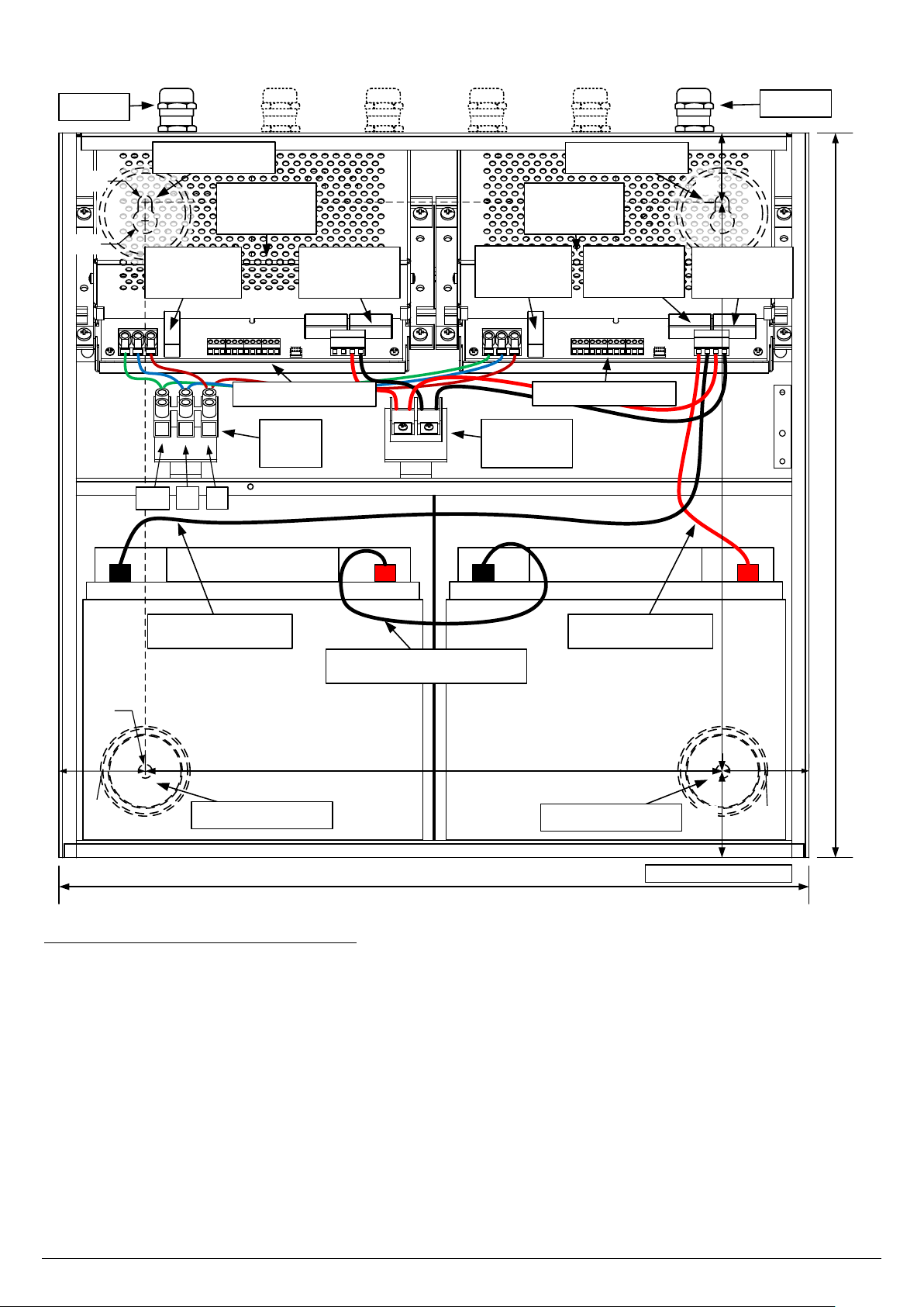
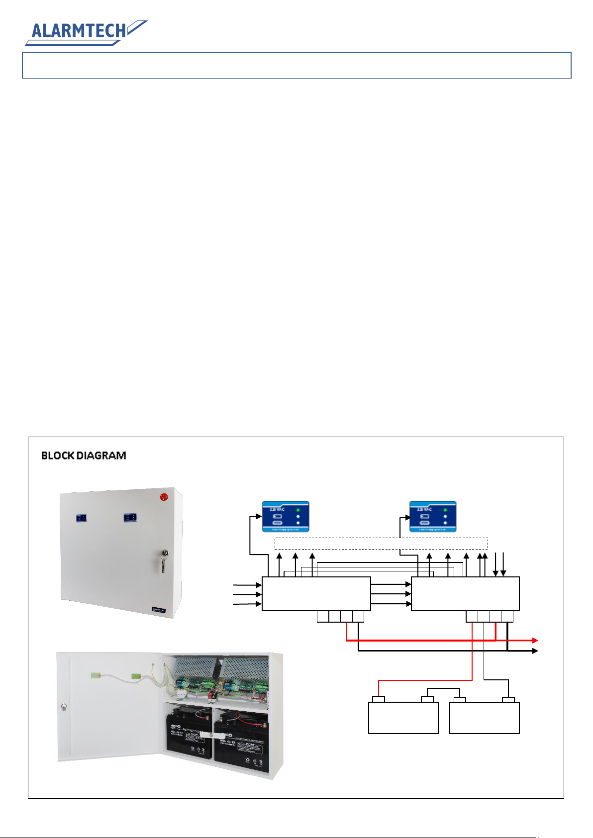
Capable to work with a pack of two 12 V/40 Ah sealed lead
acid batteries
Short circuit and overload protection
Detection of no mains supply (EPS fault)
Detection of different battery faults (APS fault) –not con-
nected, low voltage, high internal resistance
Detection of low output voltage (OUT fault)
Detection and LED identification of broken fuses
Detection of power unit failure
Deep discharge protection of battery (DDP)
Built-in high voltage protection circuit
Remote and local battery testing
Tamper security provided –case opening and pry-off
Remote
battery
test
230 VAC
12V battery
40 Ah
12V battery
40 Ah
Front panels
L
PE
N
24 VDC output
EPS, APS, OUT, SAB, SDT
PSV-2465
EPS, APS, OUT, SAB, SDT
PSV-2465
-
Signalling outputs
+
+
-
-
+
+
-
EPS –External Power Supply (mains)
APS –Alternative Power Source (battery)
OUT - Output voltage
SAB –Sabotage
SDT –Storage Device Test
(battery test)
©2014 Alarmtech 2 / 4 PSV 24130-40 manual 1421en
1. INSTALLATION
Power supply installation and start-up procedure:
Break-out pre-cut openings on top side of the case and install
cable glands: one for 230 VAC input on the left side and
planned number (1 to 5) for output cables
Remove power units from DIN-rail to get access to upper
mounting holes
Fix unit in destination place using 4 fixing holes
Install back both power units on DIN-rail
Place two batteries 12 V/40 Ah in battery chambers
Make internal connection in battery pack connecting left bat-
tery (+) with right battery (-) with the help of grey cable
Make connection with black battery cable between left bat-
tery (-) and BAT- terminal in PSV-2465 unit (placed on right
side)
Make connection with red battery cable between right bat-
tery (+) and BAT+ terminal in PSV-2465 unit (placed on right
side)
Make appropriate connections between power output and
power receivers - carry out to the load using necessary num-
ber of outputs and cable glands
The socket outlet delivering 230 VAC shall be installed near
the power supply unit and shall be easily accessible
Make sure that cable delivering 230VAC to PSV 24130-40 is
disconnected from mains
Carry in cable delivering 230 VAC to the unit using separate
cable gland on the left side and connect it to 230 VAC input of
power unit PSV-24130 –make sure that PE cable is connected
to PE input
Switch on mains delivering energy to power supply - PSV
24130-40 unit will start automatically delivering power to the
load and monitoring state of PS
Battery #1
12 V, 40 Ah
+
-
Battery #2
12 V, 40 Ah
+
-
Cable between batteries
Battery cable (+)Battery cable (-)
435 (440 with lid)
Case fixing hole
50 50
Case fixing hole
335
All dimensions in [mm]
420 (425 with lid)
40
50 330
Ø8
Ø8
NL
Output
connector
Mains
input
Output fuse
6.3 A, fast
Battery fuse
10 A, fast
Output fuse
6.3 A, fast
Mains fuse
2.5 A, slow
Mains fuse
2.5 A, slow
Outputs
230 VAC
Ø14
Power Unit
PSV 2465
Power Unit
PSV 2465
Case fixing hole Case fixing hole
PE
+ OUT -
Signalling outputs Signalling outputs
©2014 Alarmtech 3 / 4 PSV 24130-40 manual 1421en
2. TECHNICAL DESCRIPTION
2.1 Front panels
Power supply unit is equipped with two front panels showing actual general state of both power units. Three LED’s display shows:
Green LED: mains voltage present –unit in EPS mode supplied from mains
Yellow LED: mains voltage missing –unit in APS mode supplied from battery
Red LED: fault detected –quick visual identification and localisation of failure is possible with help of set of diagnostic LED’s
in power unit
2.2 Internal state monitoring functions in power units
All monitored states of power units are displayed with help of LED diodes for quick visual identification and localization. The placement
of monitoring LED is documented in below placed drawings. The meaning of LED colours is following:
Green - normal state, OK
Red - fault detected
Yellow - informative meaning (neutral)
EPS APS OUT SAB SAB -SDT*
SDT START
KICK-
Alarmtech ViP
F3
N L +BAT- VOUT COM
F2
F1
Power Supply
24 V battery pack recharging
Output 24 V
Input AC voltage
To tamper switches
Tamper
fault output
Storage Device Test input (*)
Storage Device Test ground (-)
EPS fault output (isolated)
APS fault output (isolated)
OUT fault output (isolated)
Kick
start
jumper LED yellow: battery recharging enabled
LED red: APS fault LED red: OUT fault
LED green: output voltage OK
Battery fuse,
10 A, fast
Output fuse,
6.3 A, fast
Input fuse, 2.5A, slow
Open: battery circuit enabled
Closed: battery circuit disabled
Closed-to-open: battery test triggered
Front panel / USB link
PSV-2465
F1: T 2.5H25 0V
F2: F 6.3H25 0V
F3: F10 H25 0V
Battery recharg.
current = 1.5 A
LED red: EPS fault
230 VAC
Power Supply 24 VDC
+_
230 VAC
Power Supply 24 VDC
+_
230 VAC
Power Supply 24 VDC
+_
230 VAC
Power Supply 24 VDC
+_
Unit state OK
Supplied from mains
Battery OK
Output OK
No faults reported
Missing mains
(EPS output triggered)
Supplied from battery
No other faults
PS supplied from mains
Possible fault detected:
-APS (battery)
-OUT (output)
Missing mains
(EPS output triggered)
Supplied from battery
Possible faults detected:
-APS (battery)
-OUT (output)
©2014 Alarmtech 4 / 4 PSV 24130-40 manual 1421en
2.3 Jumpers in power units
Power unit is equipped with 2 jumpers placed on PCB:
Kick-start jumper (default position: open)
Momentary shunt
Kick-start of PS from battery (w/o mains)
Open (default)
Deep Discharge Protection (DDP) of battery enabled
Closed
Deep Discharge Protection (DDP) of battery disabled
SDT (Storage Device Test) jumper (default position: open, active only in right PSV-2465 unit)
Momentary shunt
Battery test trigger (30s test of internal battery circuit resistance)
Open (default)
Battery recharging circuit enabled
Closed
Battery recharging circuit disabled
2.4 Input/output terminals
Input / Output
Marking
Description
Mains input with PE
PE, N. L
230 VAC input
Mains failure signalling
EPS
Potential free NC opto-relay output signalling EPS fault
Battery failure signalling
APS
Potential free NC opto-relay output signalling APS fault
Output failure signalling
OUT
Potential free NC opto-relay output signalling OUT fault
SAB Tamper output/input
SAB, SAB
Potential free NC micro-switch connection points
Storage Device Test trigger
-SDT*
Test triggered by momentary shunt between (-) and (*)
Battery pack connection
+BAT-
(+) and (-) terminals for 2x12 V battery pack connection
Power output
VOUT COM
(+) and (-) terminals for power output
3. TECHNICAL SPECIFICATION
Type of Power Supply acc. to EN 50131-6:2008: type A
Security grade acc. to EN 50131-6:2008: grade 3
Nominal input voltage rating: 230 VAC, 2.5 A with maximal load, 50 Hz
Nominal output voltage: 27.6 V
Minimum output voltage in battery mode: 20.0 V (in APS mode)
Total rated output in grade 3: 0.95 A (30 h in APS mode with 40 Ah batteries)
Total maximal output to installation: 11.4 A in grade 3
Quiescent current consumed by built-in modules: 0.12 A
Maximum output ripple voltage: < 50 mVpp
Battery pack type: Two 12 V/40 Ah sealed lead acid batteries in series
Battery recharging method: constant potential –limited current
Maximum battery recharging current: 1.5 A (grade 3)
Time to recharge batteries to 80%: 24 h max
Over-voltage protection trigger level: 34.5 V
Battery pack voltage triggering APS fault: 22 V
Battery pack voltage triggering DDP circuit: 19 V (Deep Discharge Protection level)
Output voltage triggering OUTPUT fault: 18 V
Monitoring outputs: EPS –loss of mains
(Outputs signalling faults: EPS, APS and OUT APS –battery pack low voltage, battery failure, disconnected
from both PSV units are connected in series) OUT –output voltage low, power unit failure
SAB –case tampering
Electrical characteristics of monitoring outputs: - Opto-isolated semiconductor relay for EPS, APS, OUT
-Micro-switch for case tampering
Logical characteristics of monitoring signals: Closed state –monitored condition not present
Open state –monitored condition present
Remote battery test input: -SDT* - shunt between terminals (-) and (*) triggers 30 s test of internal
battery circuit resistance
Remote battery test acknowledgement: APS output
Local battery test trigger: SDT jumper, momentary shunt (PSV-2465 unit only)
Automatic battery diagnostics procedure: executed every 10 h automatically
Operating temperature and humidity range: -10 ºC…+55 ºC, RH to 90%, no condensation
Environmental Class acc. to EN 50130-5:1998: Class II
Weight without batteries: approx. 11 kg
Weight with batteries: approx. 37 kg
Dimensions: 440 x 425 x 200 mm (W x H x D)
Compliance:

Other Alarmtech Power Supply manuals

Alarmtech PSV 2435-12 User manual

Alarmtech

Alarmtech PSV 2435-12 User manual

Alarmtech PSV 2435-40 User manual

Alarmtech

Alarmtech PSV 2435-40 User manual

Alarmtech PSV 2465-12 User manual

Alarmtech

Alarmtech PSV 2465-12 User manual

Alarmtech PSV 1215-18 User manual

Alarmtech

Alarmtech PSV 1215-18 User manual

Alarmtech PSV 1225-18 User manual

Alarmtech

Alarmtech PSV 1225-18 User manual

Alarmtech PSV 24100-12 User manual

Alarmtech

Alarmtech PSV 24100-12 User manual

Alarmtech PSV 2415-12 User manual

Alarmtech

Alarmtech PSV 2415-12 User manual

Alarmtech PSV 2465-40 User manual

Alarmtech

Alarmtech PSV 2465-40 User manual

Popular Power Supply manuals by other brands

Beckhoff C9900-P223 Installation and operating instructions

Beckhoff

Beckhoff C9900-P223 Installation and operating instructions

MAASLAND KSG1C quick start guide

MAASLAND

MAASLAND KSG1C quick start guide

ODA OPX-93D user manual

ODA

ODA OPX-93D user manual

Würth 0827 940 213 operating manual

Würth

Würth 0827 940 213 operating manual

Rohde & Schwarz HMC804 user manual

Rohde & Schwarz

Rohde & Schwarz HMC804 user manual

Teledyne T3PS16081P user manual

Teledyne

Teledyne T3PS16081P user manual

COUGAR STC750 manual

COUGAR

COUGAR STC750 manual

Well Tempered Lab WTL Phono instruction manual

Well Tempered Lab

Well Tempered Lab WTL Phono instruction manual

Aiphone PS-18YC/A specification

Aiphone

Aiphone PS-18YC/A specification

Pulsar BLACK POWER PSBEN 5012D/LCD manual

Pulsar

Pulsar BLACK POWER PSBEN 5012D/LCD manual

Avansa 500 W operating instructions

Avansa

Avansa 500 W operating instructions

EnerSys alpha Cordex CXRF 48-3.6kW Technical guide

EnerSys

EnerSys alpha Cordex CXRF 48-3.6kW Technical guide

MANGO POWER E quick start guide

MANGO POWER

MANGO POWER E quick start guide

Rigol DP1308A Service guide

Rigol

Rigol DP1308A Service guide

Altimium PWSU12 user manual

Altimium

Altimium PWSU12 user manual

iseg SHR Standard user manual

iseg

iseg SHR Standard user manual

PS Audio AV-3000 Owner's reference

PS Audio

PS Audio AV-3000 Owner's reference

Thermal Dynamics 38 Cutmaster instruction manual

Thermal Dynamics

Thermal Dynamics 38 Cutmaster instruction manual

manuals.online logo
manuals.online logoBrands
  • About & Mission
  • Contact us
  • Privacy Policy
  • Terms and Conditions

Copyright 2025 Manuals.Online. All Rights Reserved.