6
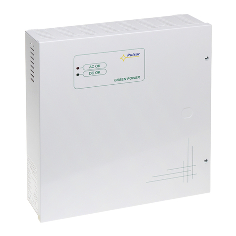
ON - the power pack is supplied with voltage 230V AC
OFF - the power pack is not supplied with voltage 230V AC
GREEN DIODE
ON – DC voltage at the output of the power pack
OFF – DC voltage missing at the output of the power pack
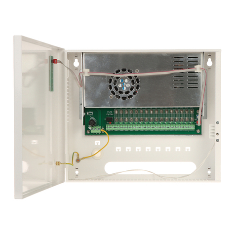
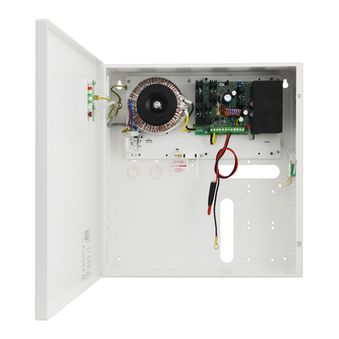
4. Connect the leads of the consumers to joints OUT + and - of the joint box on the power pack board [6].
(Optionally connect the MZN1 module between +OUT- and load).
5. Activate the 230 V AC power supply and insert the power network fuse protecting the transformer primary circuit
[9]. Check the optical signalling of the power pack operation. The output voltage of the unloaded power pack is
equal to ~ 13.8 V C. The voltage may fluctuate from 12.8 V to 13.8 V C during battery charging.
6. Connect the battery in accordance with the designations [7] with colours. After this operation is completed, the
voltage appears in the output of the power pack, which is signalled by the green diode on.
7. Perform the power pack test checking the optical signalling [4] [5]: - the disconnection of the voltage 230 V AC
through the removal of the fuse from the transformer socket will be signalled by the red diode going off.
8. Following the assembly and checking the correctness of operation, the enclosure may be locked.
3.
Handling and operation.
3.1
Power pack operation signalling.
The unit is equipped with the optical signalling of operation states:
- LE on - LE off
Description Comments
Proper state of operation
Output overloaded or short
circuited
- check cabling and consumers
- if the battery is connected, check
battery fuse
The absence of power
supply from the power
- check transformer fuse
The absence of voltage at
the output
- check cabling and consumers
- check transformer fuse
- check battery fuse
flickers
Output overloaded - lower the consumption of current by
consumers
Tab.4.
Optical signalling.
3.2
Operation from the attery.
Starting the operation from the attery.
The time of operation with supplies from battery depends on the battery capacity, the extent of charging and the
load current. For example, for the typical, fully charged battery with capacity of 7 Ah and load current 1A, the maximum
operation time safe for the battery is approximately five hours.
Starting the power pack from the attery: after connecting the battery in accordance with the designations [7],
the voltage appears on the output terminals of the power pack.
The limitation of the attery charging current.
The power pack is equipped with the battery charging current limitation to the value Iacc (max) =~ 300mA.
3.3
Procedures in the case of power pack overloading.
The power pack is equipped with the protection of the output stage with the application of the PTC polymer fuse.
When the power pack is loaded with current exceeding 1A (110%
÷150% P)
, the automatic disconnection of the output
voltage takes place which is signalled by the green diode going off. In such a case, the load should be disconnected from
the output of the power pack for the period of about 1 minute.
