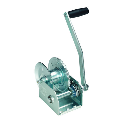
Alba 8A User manual


8A-16A-32A Page 1 of 28
TABLEOFCONTENTS
1DESCRIPTION........................................................................................................................................3
1.1INTRODUCTION...........................................................................................................................................3
1.2GENERALINFORMATION...............................................................................................................................4
1.3CHECKSONDELIVERY...................................................................................................................................5
1.4TRANSPORT...............................................................................................................................................6
1.5INTENDEDUSES..........................................................................................................................................6
1.6CHARACTERISTICS........................................................................................................................................7
1.7DIMENSIONS..............................................................................................................................................7
2INSTALLATION......................................................................................................................................8
2.1COMMISSIONING........................................................................................................................................8
2.2FASTENINGTHETRACTIONANDLIFTINGAPPARATUS........................................................................................11
2.3HOOKINGUPTHELOAD..............................................................................................................................12
3USE.....................................................................................................................................................15
4SAFETY................................................................................................................................................17
4.1SAFETYSTANDARDS...................................................................................................................................17
4.2SAFETYDEVICES........................................................................................................................................17
4.2.1Individualprotectionequipment(IPE).............................................................................................19
5MAINTENANCE...................................................................................................................................20
5.1MAINTENANCEOFTHELIFTINGAPPARATUS...................................................................................................20
5.1.1ProcedureforcleaningtheLiftingApparatus..................................................................................21
5.2MAINTENANCEOFTHECABLE......................................................................................................................21
5.2.1MaintenanceofthecouplingontheendoftheCable.....................................................................23
5.3LOCATINGANDDEALINGWITHFAULTS...........................................................................................................24
6STORAGE............................................................................................................................................25
7PROHIBITEDMODESOFUSE................................................................................................................26
8GUARANTEE........................................................................................................................................27
9“CE’’DECLARATION.............................................................................................................................28

8A-16A-32A Page 2 of 28
ILLUSTRATIONS
FIG.1‐1‐GENERALINFORMATION.................................................................................................................................4
FIG.1‐2–MAINCOMPONENTS.....................................................................................................................................5
FIG.1‐3–TRANSPORTATIONHANDLE.............................................................................................................................6
FIG.1‐4‐DIMENSIONS................................................................................................................................................7
FIG.2‐1‐CABLE‐COUPLING‐WHEELUNIT.........................................................................................................................8
FIG.2‐2‐HOOKINGTHEALIGNMENTPININTOTHEUNLOCKINGCLAW...................................................................................9
FIG.2‐3‐INTRODUCINGTHECABLE................................................................................................................................9
FIG.2‐4–FASTENINGTHEAPPARATUSTOAFIXEDPOINT.................................................................................................10
FIG.2‐5‐PULLINGTHECABLEOUTWITHYOURHAND.......................................................................................................10
FIG.2‐6–PLACINGTHELEVERINPOSITIONANDTURNINGITHALFWAYROUNDTOPREVENTITFROMCOMINGLOOSE...................11
FIG.2‐7–COUPLINGONTHEEND................................................................................................................................11
FIG.2‐8‐FASTENINGTHETRACTIONANDLIFTINGAPPARATUS...........................................................................................12
FIG.2‐9–COUPLINGWITHASAFETYLOCK.....................................................................................................................13
FIG.2‐10‐HOOKINGUPTHELOAD..............................................................................................................................14
FIG.3‐1‐USEOFPULLEYS..........................................................................................................................................16
FIG.4‐1–SAFETYSCREW...........................................................................................................................................18
FIG.5‐1‐HOWTOMEASURETHECABLE........................................................................................................................22
FIG.5‐2–COUPLINGANDSAFETYLOCK.........................................................................................................................23

8A-16A-32A DESCRIPTION Page 3 of 28
1 DESCRIPTION
1.1 Introduction
All users of the Traction Apparatus are required to read this manual before assembling and
using the same. As such, it should be read in depth to ensure strict compliance with all the
safety standards.
The manufacturer reserves the right to effect modifications as a means of improving the
Traction Apparatus, reason for which the equipment may differ slightly to the specifications set
forth in this manual. Moreover, ALBA-MACREL GROUP S.L. undertakes to update the manual
immediately upon each improvement.
ALBA-MACREL GROUP S.L. will not be held liable for any damage arising from:
Failure to follow the instructions contained in this manual.
Using the machinery in an incorrect manner.
The use of non-original spare parts specified in the corresponding section in this
manual.
Modifications made to the machinery without the express authorisation of the
manufacturer.
Handling by personnel who have not been trained for the purpose.
The use of the Traction Apparatus should only be entrusted to trained personnel and the
handling of all components should be conducted by specialised technical personnel with
knowledge of the same.
This manual should always be kept within the reach of users for immediate consultation. We
recommend taking a copy of the manual and leaving it alongside the apparatus as a means of
ensuring it is kept in perfect condition.
The sketches and images illustrated in this manual are for the purposes of guidance and will
be updated as new designs are produced.
ALBA-MACREL GROUP S.L. hopes this Traction Apparatus performs to your complete
satisfaction.

8A-16A-32A DESCRIPTION Page 3 of 28
1.2 General Information
This Apparatus is specifically designed to handle load son vertical, horizontal and inclined
planes as illustrated in the sketches in Fig. 1-1.
The weights capable of being handled are specified in the table in section 1.6.
In the event of the need to handle greater weights, different pulley systems can be used.
The lifting device is a portable apparatus equipped with a pass-through cable which is drawn
in a straight line by clamps. The stress is transferred to the Manoeuvre Levers (up or down)
through a removable lever (Drive Lever).
It features a safety system whereby the Apparatus cannot be unlocked in order to remove the
Cable when it is loaded. It also features a device which prevents the scaffold from being raised
when it exceeds 2.5 times the work load limit.
Fig. 1-1 - General information
WARNING:
The calculation of the pulleys required to handle the loads should
be conducted by specialised personnel.
WARNING:
Even when using pulleys which ensure the handling of greate
r
weights, care should always be taken not to exceed the cable
breaking load. See the breaking load in section 1.6.

8A-16A-32A DESCRIPTION Page 3 of 28
Description of the main components of the Apparatus:
Fig. 1-2 – Main components
1.3 Checks on delivery
At the time of the delivery of the Traction Apparatus a check should be conducted to ensure:
The order matches exactly what has been delivered.
The Traction Apparatus is in perfect condition, comprising all the parts and with no
defects.
In the event of detecting an anomaly in relation to any of the aforementioned ítems,
you should contact ALBA-MACREL GROUP S.L. or their local representative
immediately.
1 Telescopic lever 7 Cable output
2 Forward lever 8 Cable input
3 Unlocking claw 9 Coupling bolt with a lock
4 Reverse lever 10 Reel
5 Safety screw 11 Coupling with safety lock
6 Alignment pin 12 Cable

8A-16A-32A DESCRIPTION Page 3 of 28
1.4 Transport
The casing of the traction apparatus features a handle to transport it.
Fig. 1-3 – Transportation handle
1.5 Intended uses
Construction
Public works
Mines and quarries
Electricity and communications
Shipyards. Shipping
Transport. Railways
Fire brigade
Garages
Agriculture. Forestry activity
Chemical and oil industry
The Armed Forces

8A-16A-32A DESCRIPTION Page 3 of 28
1.6 Characteristics
8A 16A 32A
Rated lifting capacity kg 800 1600 3200
Cable feed rate per cycle driven mm 54 58 45
Nominal stress on the lever kg 29 40 53
Net weight (with no cable-lever) kg 6,4 13,7 23,7
Weight when packed kg 7,7 16 26,3
Packaging measurements cm 44 x 9 x 28 56 x 12 x 36 70 x 11 x 38
Cable
Diameter mm 8,3 11,3 16,3
Breaking load kg 4800 9600 19200
Weight/m kg 0,27 0,51 1
1.7 Dimensions
Fig. 1-4 - Dimensions
A B C D E F G / G’ H
8A 430 170 268 18 38 109 645 60
16A 546 203 336 22 48 120 635/1055 82
32A 663 232 372 28 50 136 635/1055 105

8A-16A-32A INSTALLATION Page 8 of 28
2 INSTALLATION
Apart from the dimensions of the Traction Apparatus, the following conditions need to be
complied with:
The environment must be well lit in order to guarantee the safe use and
maintenance of the Traction Apparatus.
The work area should be of the appropriate dimensions in accordance with the
work to be executed.
The permitted operating temperature is from – 5 ºC to + 40 ºC.
The permitted relative humidity is from 30% to 90% (at 20 ºC).
The area should be protected against atmospheric agents.
2.1 Commissioning
Step Nº 1
The Cable is unrolled as illustrated in Fig. 2-1, pulling out the coupling and rolling the reel to
prevent the formation of kinks and twists.
Fig. 2-1 - Cable-coupling-wheel unit
WARNING:
If the Cable is left on the floor without rolling it in, kinks and twists
will appear which cannot be corrected and which will damage the
Cable over time.

8A-16A-32A INSTALLATION Page 9 of 28
Step Nº 2
When the apparatus has been fastened and the lever is in the reverse position, make a
parallel movement and hook the alignment pin into the unlocking claw. You can use your foot
to help you do this.
Fig. 2-2 - Hooking the alignment pin into the unlocking claw.
Step Nº 3
Place the cable into the opening indicated by the arrow without forcing it until it comes out
through A. In the event of difficulty, pull the cable out around 3 cm and push it through again
while turning it at the same time.
Fig. 2-3 - Introducing the cable
WARNING:
Do not leave the apparatus unlocked for any length of time.

8A-16A-32A INSTALLATION Page 10 of 28
Step Nº 4
Use the coupling bolt to fasten the Apparatus to a suitable fixed point.
Turn the bolt in two movements, pushing it in up to the second groove, fixing it with its cam.
This bolt is the only place in which the apparatus should be fastened (slung or well coupled)
in order to use it.
Fig. 2-4 – Fastening the Apparatus to a fixed point
Step Nº 5
Pull the cable out of the opening until it is tight.
Fig. 2-5 - Pulling the cable out with your hand
Step Nº 6
Placing the apparatus in reverse gear, remove the alignment pin from the unlocking claw.
Place the lever in forward or reverse gear and turn it halfway round to prevent it from coming
out.
The Apparatus is ready for use.

8A-16A-32A INSTALLATION Page 11 of 28
Fig. 2-6 – Placing the lever in position and turning it halfway round to prevent it from coming loose
2.2 Fastening the Traction and Lifting Apparatus
The Traction Apparatus is equipped with a coupling bolt at one end to fasten it to a suitable
fixed point.
Fig. 2-7 – Coupling on the end
A steel sling or coupling needs to be used to fasten it, and never the cable extending from
the Apparatus. This cable should come out freely and you should not use any type of device
which subjects it to stress.
WARNING:
The point to which the traction device is fastened should be
prepared to withstand the load with a considerable safety margin.
The choice of an unsuitable fastening point could cause an
accident.
WARNING:
The only way of fixing the Apparatus is by attaching the sling o
r
hook to the coupling bolt. Never attach it to the casing o
r
transportation handle.
Coupling bolt

8A-16A-32A INSTALLATION Page 12 of 28
CORRECT NEVER
Fig. 2-8 - Fastening the traction and lifting apparatus
2.3 Hooking up the load
The cable supplied with the Apparatus is equipped with a coupling with a safety lock at one
end.
WARNING:
Do not use the cable exiting the traction apparatus to fasten o
r
sling any type of device.
WARNING:
Do not use the cable exiting the traction apparatus to attach it to
another traction device.
WARNING:
Never fasten the Apparatus by leaning or clamping the casing, as
this could deform it and cause the Apparatus to malfunction.

8A-16A-32A INSTALLATION Page 13 of 28
Fig. 2-9 – Coupling with a safety lock
In order to attach or remove the coupling device (eyelet, grommet, thimble, etc.) you need to
press the safety lock into the coupling, whereby it will return to its original position
automatically when the operation has been concluded.
If the load is equipped with one or more specific dragging and/or lifting points, the cable
coupling will need to be placed, directly or using a sling, on these points, always taking the
stability of the load into account when moving it.
If the load has no specific dragging and/or lifting points, it will need to be tied to the cable
coupling using slings, taking care not to damage it and taking the stability of the load into
account when moving it.
WARNING:
Never use the traction apparatus cable to secure or sling loads.
WARNING:
The coupling safety lock should not be off when the load is being
moved.
WARNING:
The load should be correctly tethered and secured before starting
to move it.
Safety lock

8A-16A-32A INSTALLATION Page 14 of 28
CORRECT NEVER
Fig. 2-10 - Hooking up the load

8A-16A-32A USE Page 15 of 28
3 USE
Read this manual thoroughly before using the Traction Apparatus. The incorrect use of the
same may cause harm to persons and damage the equipment.
There follows a series of preconditions in relation to the use of the Traction Apparatus which
should be complied with:
The Traction Apparatus should only be used for the purpose it was designed for.
The Traction Apparatus should only be used by authorised personnel who have
been trained to handle this type of equipment.
The operator should be familiar with the handling of the Traction Apparatus before
using it for the first time. He/she should know the function of each lever and/or
device, in addition to the possibilities and limitations of the Traction Apparatus with
the aim of reacting quickly in the event of any unforeseen circumstance.
The Traction Apparatus should not be used in the event an anomaly is detected on
the daily inspection or during use.
The Traction Apparatus should not be used in the event the required installation,
use and maintenance conditions set forth in the different sections of this manual
have not been met.
Prior to being placed in position and after being transported, the structure of the
Traction Apparatus should be checked for damage suffered from impact or falls
which might compromise the performance of the same.
Once the instructions in relation to commissioning have been complied with, the following
checks should be conducted before using the traction equipment:
The Apparatus should always be aligned with the cable, reason for which there
should be no obstacles in its longitudinal path.
Care should be taken to prevent the cable from coming into contact with kerbs,
corners or similar during use, and pulleys can be used for this purpose.
Hung loads need to be prevented from spinning, as this will damage the cable.
WARNING:
The length of the cable should be greater than the length of the
operation to be executed. A longer cable may be used when
necessary, however extensions should never be attached to the
original cable. .
WARNING:
Only the special ALBA cable should be used.

8A-16A-32A USE Page 16 of 28
CORRECT NEVER
Fig. 3-1 - Use of pulleys
After having followed the instructions and there is no sign of any hazard which might arise
during the normal use of the Apparatus, it may be used as described below:
With the lever in forward or reverse gear, as applicable, the equipment will move
back-and-forth in a longitudinal direction.
The maximum range of this back-and-forth movement is that of the Apparatus itself.
The path of the lever will depend on the intent of the user, never beyond the limit of
the Apparatus.
WARNING:
In order to guarantee the equipment performs well, never engage
the two gears (forward and reverse) at the same time.
WARNING:
Do not force or obstruct the normal path of the levers.
WARNING:
Oiling of the Apparatus after using it for the first time (See the
maintenance section).
WARNING:
The Apparatus should be oiled in the event the lever becomes stif
f
in reverse or down gear or after lengthy use (See the maintenance
section).

8A-16A-32A SEGURIDAD pág. 17 de 28
4 SAFETY
4.1 Safety Standards
Failure to comply with the following safety standards may place users of the Traction
Apparatus and exposed persons at risk. The following actions are STRICTLY PROHIBITED:
Using the Traction Apparatus with a load over its nominal capacity.
Using the Traction Apparatus for work other than that it was designed for.
Obstructing the movement of the up or down lever.
Engaging the up and down levers at the same time.
Using any means of engaging the equipment other than the original drive lever.
Replacing the original safety screw with one of a different origin.
Fastening the Traction Apparatus using means other than the fastening coupling.
Attaching a load to the end of the Cable which protrudes over the side of the
fastening device.
Striking the drive components.
Exposing the Cable to temperatures of over 100 ºC and/or chemical or mechanical
agents.
Using the Cable to sling a load.
Allowing the Cable to come into contact with sharp edges.
Using Cables without oiling them.
Allowing a Cable under stress to come into contact with an obstacle.
Using a Cable of a length less than that of the operation to be executed.
4.2 Safety Devices
ALBA traction equipment features a safety device against overloading in forward gear,
consisting of a screw with a safety nut. This device restricts overloading and protects the
mechanism. It prevents the load from being hoisted in the event it registers more than 2.5
times the limit of the work load when operating with a force of up to 1 kN on the end of the
lever.

8A-16A-32A SEGURIDAD pág. 18 de 28
8A-16A-32A Rev.00-EN
(+34) 944 71 16 00 (+34) 944 53 17 54 [email protected]
www.alba.es
Fig. 4-1 – Safety screw
In the event the safety screw breaks, the Traction Apparatus will be prevented from lifting
and the following steps should then be taken:
Guarantee the safety of the load.
Unhook the Apparatus.
When you are sure there is no risk involved in the operation, replace the broken
safety screw with an identical original.
The cause of the overloading needs to be ascertained before using the Traction
Apparatus again. The appropriate pulleys or a traction device with a greater
capacity can be used for this purpose.
WARNING:
In the event the safety screw breaks, never replace it with one othe
r
than the type supplied. The use of any other type of safety scre
w
implies “unknown” behaviour in relation to overloading, with all the
consequences this might involve. Contact your retailer or manufacture
r
for spare parts.
Safety screw

8A-16A-32A SEGURIDAD pág. 19 de 28
4.2.1 Individual protection equipment (IPE)
The IPE we recommend wearing is listed below:
Safety footwear: The use of this type of footwear on the worksite is mandatory. It
should feature anti-perforation and anti-slip soles.
A hard hat: The use of a helmet is mandatory due to the risk of falling objects and
impact to the head.
Work gloves: to handle the Cable and to prevent the risk of abrasions and cuts.
A reflective vest or clothing: mandatory when vehicles are operating in the vicinity.
WARNING:
Never replace the safety screw when the Apparatus is loaded.
This manual suits for next models
2
Table of contents
Popular Winch manuals by other brands

ETC
ETC Hammerhead HG12 Operator and maintenance manual

Winchtech
Winchtech 5900 Operating and safety instructions

Falltech
Falltech 022420 User instruction manual

Fransgard
Fransgard W-8016-EH Handbook

PFAFF silberblau
PFAFF silberblau DGUV V54 Translated Operating Instructions

Maxwell
Maxwell VWC 1000 50TDC manual

aci
aci snowsport installation instructions

Landworks
Landworks LWB0301 instruction manual

Superwinch
Superwinch ATV1800 owner's manual

HSS Hire
HSS Hire 70756 Operating & safety guide

PFAFF silberblau
PFAFF silberblau COLUMBUS McKINNON SW K LAMBDA BGV C1 Translated Operating Instructions

Harken
Harken Performa Winch 70.3 STP Installation and maintenance manual