Albalá Ingenieros, S.A. SSW3000C01 User manual

SSW3000C01
DVB-ASI AUTOMATIC CHANGE-OVER SWITCH WITH TS FAILURE
DETECTION FUNCTIONS AND SEAMLESS SWITCHING
Version 1.0
Albalá Ingenieros, S.A.
Medea, 4 - 28037 Madrid - Spain
05 December 2014 - © Albalá Ingenieros S.A. - All rights reserved

SSW3000C01

SSW3000C01
DVB-ASI AUTOMATIC CHANGE-OVER SWITCH WITH TS FAILURE DETECTION
FUNCTIONS AND SEAMLESS SWITCHING
Version 1.0
1. DESCRIPTION ...................................................................................................................... 5
1.1. The SSW3000C01 ........................................................................................................................... 5
1.2. Features ............................................................................................................................................. 6
1.3. Block diagram .................................................................................................................................. 7
2. SPECIFICATIONS ................................................................................................................. 9
3. INSTALLATION .................................................................................................................. 11
3.1. Initial inspection .......................................................................................................................... 11
3.2. Safety instructions ...................................................................................................................... 11
3.3. Environmental considerations ................................................................................................ 12
3.4. Power considerations ................................................................................................................. 12
3.5. Installing the module in the mounting frame ................................................................... 12
3.6. Interconnection ............................................................................................................................ 14
3.6.1. Electrical DVB-ASI video connections .......................................................................... 15
3.6.2. GPIO connections ................................................................................................................ 15
4. OPERATION ...................................................................................................................... 17
4.1. Front panel description .............................................................................................................. 17
4.2. Functional description ............................................................................................................... 19
4.2.1. Operation in automatic mode: ...................................................................................... 19
4.2.2. Operation in semiautomatic mode: ............................................................................. 19
4.2.3. Operation in manual mode: ............................................................................................ 19
4.3. Module remote control and supervision ............................................................................. 21
4.3.1. Details of the SSW3000C01 registers .......................................................................... 22
5. GLOSSARY ........................................................................................................................ 25
6. REGULATIONS .................................................................................................................. 27
7. VERSIONS ......................................................................................................................... 29

SSW3000C01

Albalá Ingenieros | Manual SSW3000C01
1. DESCRIPTION
1.1. The SSW3000C01
The SSW3000C01 automatic switch is a DVB-ASI signal selector that operates depending
upon the presence of signal at the inputs, presence of TS sync and the status of the GPI
inputs based upon a given set of priorities.
The SSW3000C01 includes three inputs: Main,Reserve and Auxiliar. Whichever input is
selected is then distributed to three outputs. If the power supply fails or the main board
of the module is removed from the mounting frame then the rear board will perform a
bypass from the Main input to one of the three outputs.
Depending upon the type of data stream received the SSW3000C01 can function in two
different modes: the first is valid for all DVB-ASI signals whereas the second can only be
used for DVB-T type ASI streams. The characteristics of each mode are as follows:
• Generic DVB mode:
- Not capable of seamless operation.
- Failure detection for signal level and presence of TS sync for DVB streams.
- The 1 PPS reference input is not used.
- Does not introduce any significant delay between the input and the output.
• Dedicated DVB-T mode:
- Capable of seamless operation.
-Failure detection for signal level, and presence of TS sync for DVB streams and
presence of megaframe sync (MIP packets).
-The 1 PPS input is used to measure the delays with which the input signals arrive and
to set the delay for the signal outputs.
-Output delay with respect to the 1 PPS reference is configurable and is independent
from the delay of the input signals. Output delay must be greater than the input
delay in order for the equipment to operate properly.
-Each input includes a buffer of up to 13900 packets that allow delays to be set of up
to one second at bitrates of 20Mbit/s.
The SSW3000C01 includes three switching modes: selection of the source can be
automatic, semiautomatic or manual. Any changes in source selection are indicated with
an LED and an audible beep.
5

Albalá Ingenieros | Manual SSW3000C01
It is possible to monitor the SSW3000C01 status remotely using a communications
controller module installed in the same mounting frame. In addition, certain controller
modules provide SNMP management and the ability to record events in a file including
date and time information for further analysis.
The SSW3000C01 is a TL3000 terminal line module and can be housed in a three rack
unit (3 RU) UR3000 mounting frame or a 1 RU UR3100 mounting frame.
1.2. Features
•Automatic change-over switch for DVB-ASI type TS signals with seamless switching
capabilities.
• Switches between three input sources.
• Provides automatic equalizers at the inputs.
• The failure detection criteria are as follows:
- Signal presence.
- Frame synchronization.
- Megaframe synchronization (only in DVB-T mode).
• Provides an external fault indication GPI input for each of the signal sources.
• Seamless switching between the three inputs (only in DVB-T mode).
• The selected input is distributed to all three outputs.
• Provides three modes of operation: Automatic, Semiautomatic and Manual.
• Main input will be bypassed to one of the outputs in case of power loss.
• Front panel failure indicators for main, reserve, auxiliary and 1 PPS inputs.
•Front panel indicators for absence of signal, the input selected, operating mode,
seamless switching capability.
• Acoustic and visual indicators warn against changes in the selected source.
•Module control and supervision can be done remotely when the mounting frame is
equipped with a communications controller module.
•One UR3000 mounting frame can house up to 12 SSW3000C01 modules. If power
supply redundancy is required and FA3000 or FA3001 modules are used then only 10
modules can be housed in the mounting frame. If PSU3300 or PSU3301 modules are
used for this purpose then up to 12 modules can be installed.
• One UR3100 mounting frame can house up to three SSW3000C01 modules.
• Low power.
6

Albalá Ingenieros | Manual SSW3000C01
1.3. Block diagram
7

Albalá Ingenieros | Manual SSW3000C01
SSW3000C01
8

Albalá Ingenieros | Manual SSW3000C01
2. SPECIFICATIONS
DVB-ASI signal input
Connector BNC
Impedance 75Ω ± 1 %
Return loss >17dB up to 270 MHz
Input return loss when bypass is active >17dB up to 270 MHz
Output protected with bypass relay Yes
Equalizable cable length:
Belden 8281 <80 m
DVB-ASI signal output
Connector BNC
Impedance 75Ω ± 1 %
Return loss >17dB up to 270 MHz
Output return loss when bypass is active >17dB up to 270 MHz
Input to output bypass insertion loss <0.1dB up to 270 MHz
Number of outputs 3
Amplitude 800mVpp ± 10 %
Rise and fall time (20 % - 80 %) 640 ps typ.
DVB-ASI signal
Signal format According to EN 50083-9 standard
1PPS reference signal input
Connector BNC
Impedance 50Ω ± 1 %
Type Passive Loop-Through
Threshold levels:
VIH min. 2.0 V
VIL max. 0.8 V
GPI input
Connector Plug-in terminal,
3.81mm pitch
Type 100 kΩ pull-up to 5 V
Number of inputs 3 one for each input indicating external
fail
Activation Closing contact to ground
Allowed voltage range 0 .. 24 V
GPO output
Connector Plug-in terminal,
3.81mm pitch
9

Albalá Ingenieros | Manual SSW3000C01
Type Open/closed NPN transistor collector
Number of outputs 2 one indicates TS output fail and the
other one indicates alarm
Allowed voltage range 0 .. 24V 50mA max.
General
Maximum power supply current + 410 / - 450 mA
Operating temperature range 0 .. 50 °C
Approximate weight 325 g
10

Albalá Ingenieros | Manual SSW3000C01
3. INSTALLATION
THE SSW3000C01 MODULE CONTAINS ELECTRONIC DEVICES SENSITIVE TO
ELECTROSTATIC DISCHARGE. Always use antistatic bags clearly identified
with a high degree of shielding for storage and transportation.
The SSW3000C01 module is composed of two parts: one FRS3004P06 main board and
one FRS3004P07 rear board. Both parts must be installed in a UR3000 or UR3100
mounting frame following the instructions in the corresponding section of this chapter.
3.1. Initial inspection
Verify that the package has been properly handled during transport. After opening the
packaging, check that one FRS3004P06 main board and one FRS3004P07 rear board are
inside.
You must notify your Albalá Ingenieros distributor or dealer of any damage or defects
observed.
Follow the instructions in this manual to install this module in the mounting frame.
3.2. Safety instructions
•This equipment must be connected to a mains outlet with a protective
earth connection. Never use extension cords that do not have protective
earthing connection. The lack of an effective electrical connection between
the ground pin in the mains input connector of the equipment and the
protective earth of the electrical power distribution can cause serious harm.
•All modules of the Albalá Ingenieros TL3000 terminal line can be
hot-plugged or unplugged without suffering any damage or affecting the
processes that are currently taking place in other modules in the same
mounting frame. When a module is installed in an empty bay of a mounting
frame, it is necessary to mount the rear board that is part of that module.
Prior to installing this board, the mounting frame must be disconnected
from the power supply network. This is required because in addition to the
risk of electrocution for the person handling the device it is possible that a
high instantaneous current coming from the power supply could damage
the connectors and components of the mounting frame and/or the rear
board.
11

Albalá Ingenieros | Manual SSW3000C01
•The SSW3000C01 module and the mounting frame should always be
installed, maintained, operated and removed by personnel with sufficient
technical qualifications. The equipment should never be placed in damp
areas, near splashing liquid, or in explosive or corrosive atmospheres.
Neither modules nor mounting frames can be used in applications that
could endanger human life.
3.3. Environmental considerations
This symbol indicates that this equipment must be deposited at a collection
point for proper waste treatment once it has reached the end of its useful
life.
3.4. Power considerations
The UR3000 and UR3100 mounting frames can house as many SSW3000C01 modules as
will fit in them.
3.5. Installing the module in the mounting frame
The steps needed to install the SSW3000C01 module with the rear board in the
mounting frame are:
1 - Disconnect all power cords from the power supplies of the mounting frame.
2 - Remove the blank panels covering the front and rear of the empty bays chosen for
installing the SSW3000C01 in the mounting frame.
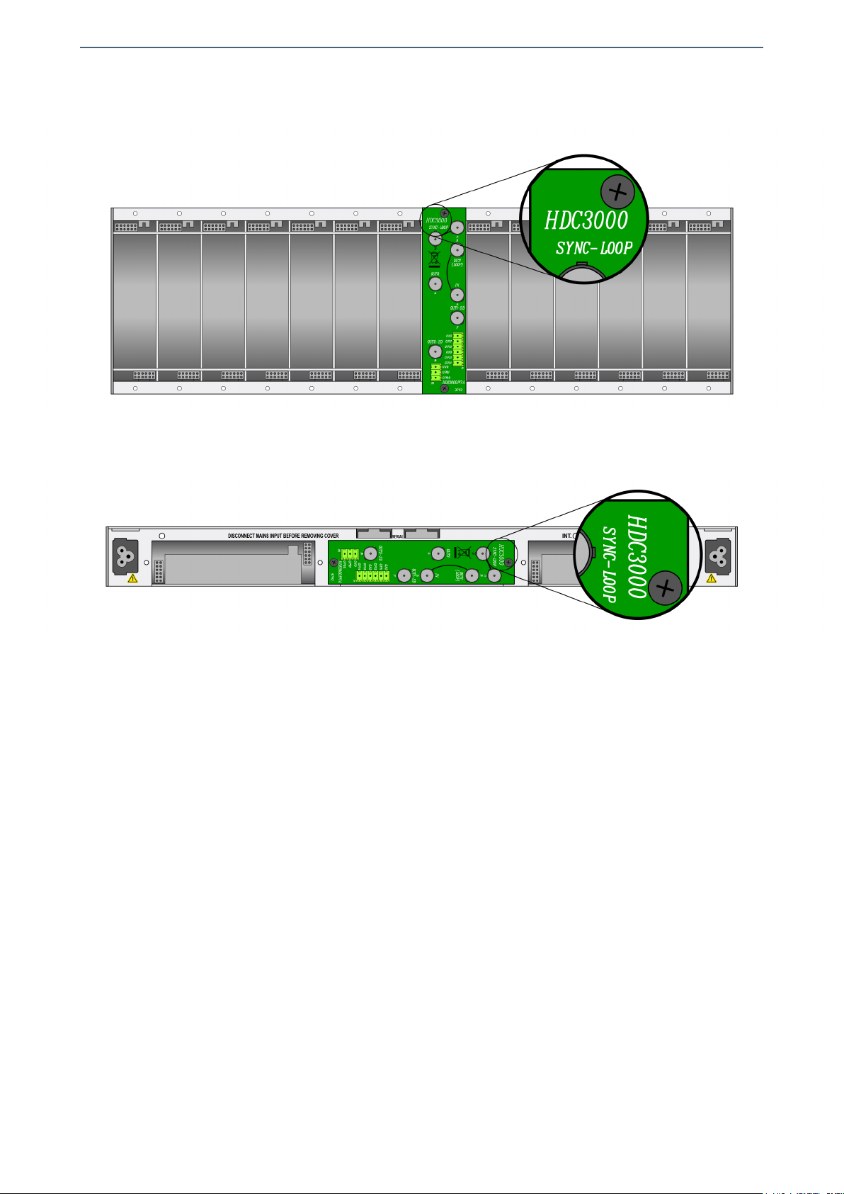
3 - Install the FRS3004P07 rear board ensuring that its 12-pin connectors are properly
aligned with the mounting frame´s mating connectors. Check that the orientation of
the board is correct by looking at the placement of the text printed on it according to
the illustration below.
4 - Attach the rear board to the mounting frame with two M3 metric screws and tighten.
5 - Insert the FRS3004P06 board (main board of the SSW3000C01 module) into the front
of the mounting frame. The edges of the card slide into two plastic guides inside the
mounting frame.
6 - Affix the main board to the mounting frame using the two screws included on the
front panel.
After these steps, the module is ready to be connected to other equipment.
12
Albalá Ingenieros | Manual SSW3000C01
Details for installation of the module in 3 RU mounting frames
Details for installation of the module in 1 RU mounting frames
13
Albalá Ingenieros | Manual SSW3000C01
3.6. Interconnection
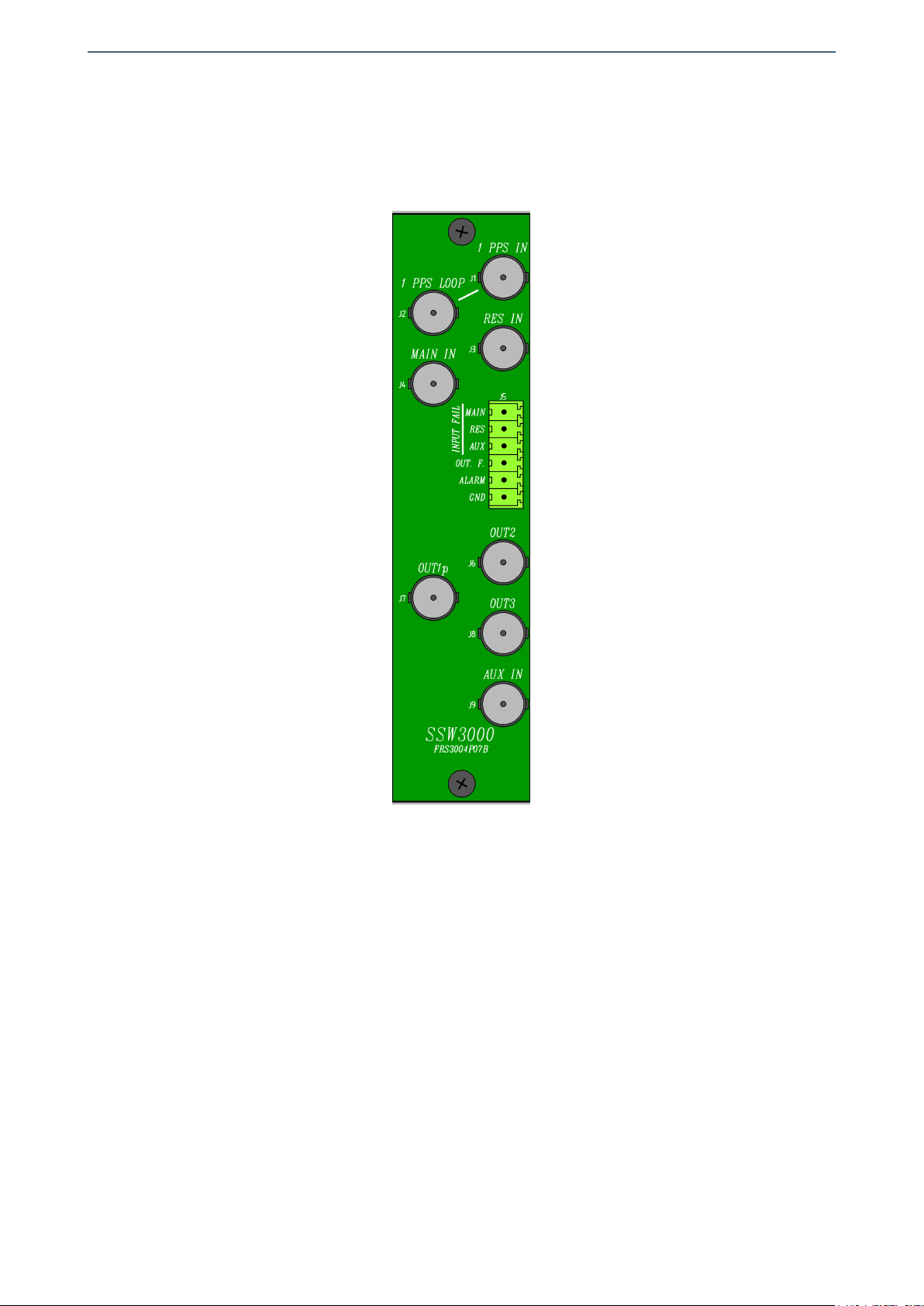
The following figure shows the SSW3000C01 module rear board connector layout.
Rear view of the SSW3000C01
The SSW3000C01 module includes three DVB-ASI signal inputs (MAIN IN,RES IN and AUX
IN) and three outputs (OUT1p,OUT2 and OUT3). The connector labeled OUT1p
corresponds to the output signal that is protected by a bypass relay. This output provides
signal continuity in case of a power supply failure or removal of the module. There are
also two 1 PPS reference loop-through inputs (1 PPS IN and 1 PPS LOOP), three GPI inputs
(INPUT FAIL MAIN,INPUT FAIL RES and INPUT FAIL AUX) and two GPO outputs (OUT. F. and
ALARM).
The rear interconnection board is not designed to withstand mechanical stress. The
wiring must be fastened properly to the frame where the mounting frame is housed to
prevent the rear board from supporting the weight of the cables.
14
Albalá Ingenieros | Manual SSW3000C01
3.6.1. Electrical DVB-ASI video connections
All DVB-ASI digital video electrical connections are BNC type. Below are several
recommendations to consider when wiring electrical signals.
BNC connectors used on cables must be suitable for the high frequencies of DVB-ASI
digital video signals: it is strongly recommended to use high quality connectors from
well known manufacturers.
All coaxial cable used must be Belden 8281 or similar. This type provides the greatest
lengths because it is used to calculate the equalizers in the SSW3000C01. Cables
carrying signal between the module and the devices should use single piece
construction, avoiding spliced sections with double BNC female or barrel connectors.
If it is necessary to split the cable into two sections the same type of wire should be
used in both sections.
The use of analog video coaxial cables (RG-59 type or similar) is not recommended for
digital video except for very short distances.
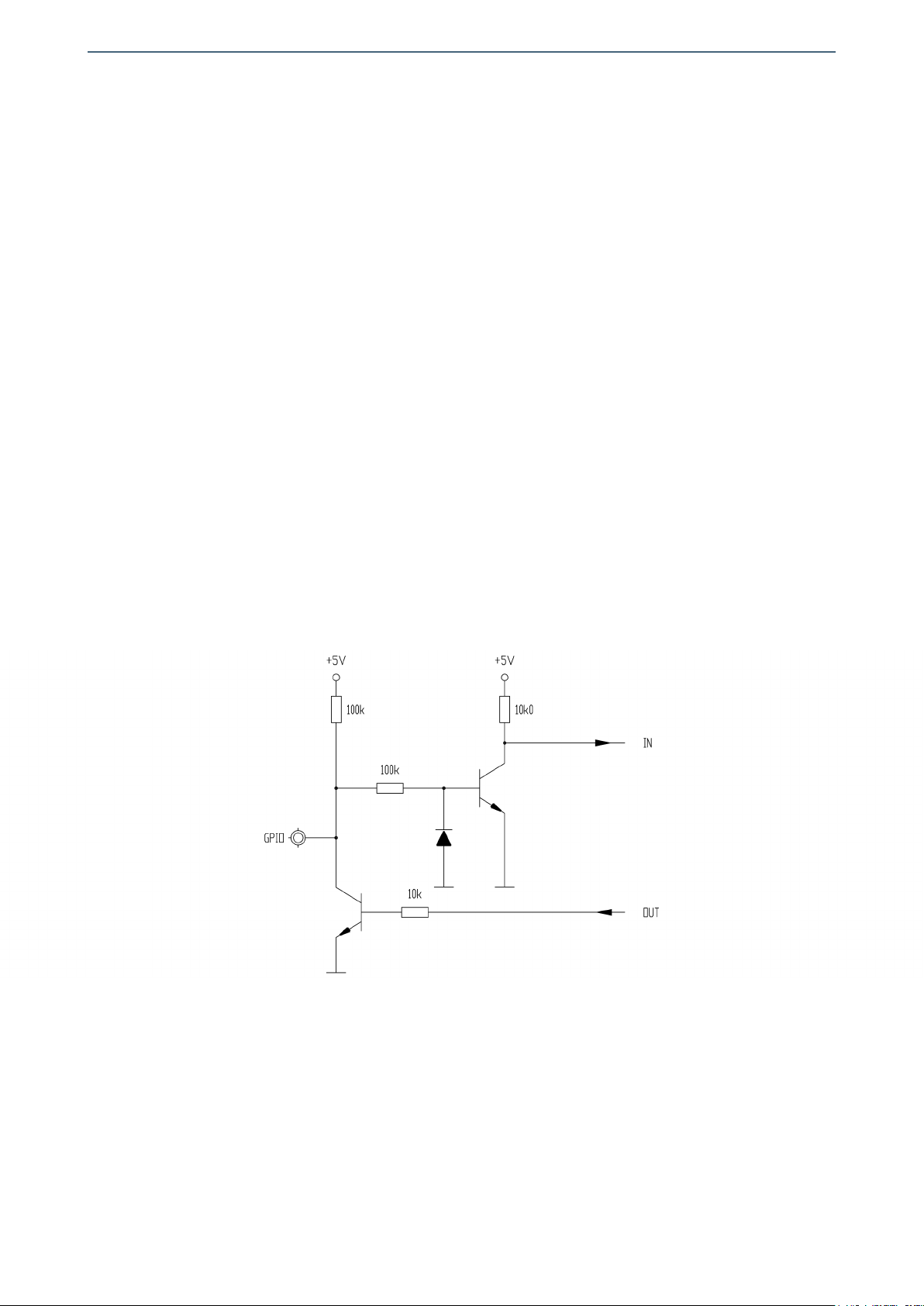
3.6.2. GPIO connections
The GPIO inputs use 3.81mm pitch terminal block connectors and correspond to the
following circuit diagram:
Review the maximum rating listed in the Specifications section before connecting
these signals. Never connect inputs with hazardous voltages to the GPIO inputs.
For construction of a GPIO connection interface cable follow the description provided
in the following box:
15

Albalá Ingenieros | Manual SSW3000C01
PIN NAME FUNCTION
6 INPUT FAIL MAIN External fault indication for the Main signal source.
5 INPUT FAIL RES External fault indication for the Reserve signal source.
4 INPUT FAIL AUX External fault indication for the Auxiliar signal source.
3 OUT FAIL This signal is active when there is no output signal.
2 ALARM This signal is active whenever the SSW3000c01 changes the
selected output.
1 GND Ground connection
16

Albalá Ingenieros | Manual SSW3000C01
4. OPERATION
This section describes the significance of the front panel indicators of the SSW3000C01
module and their remote control and monitoring ability.
4.1. Front panel description
The appearance of the front panel and the elements it contains are shown in the
following illustration.
Front panel of the SSW3000C01
The panel contains the following elements:
17

Albalá Ingenieros | Manual SSW3000C01
In the INPUT FAIL box:
MAIN,
RESERVE,
AUXILIAR: Red. These LEDs light up when no signal is present at the input, the TS
sync is incorrect, the megaframe sync is incorrect or if the
corresponding GPI failure input (INPUT FAIL MAIN, INPUT FAIL RES,
INPUT FAIL AUX) is active. These LEDs will blink when the input signal
delay is greater than the programmed output signal delay. In this case
the megaframe will begin one second later than normal.
In the SEAMLESS STATUS box:
1 PPS FAIL: Red. This LED lights up when no 1 PPS signal is detected or when the
equipment cannot sync to the 1 PPS signal due to excessive jitter.
ACTIVE: Blue. This LED lights up when seamless switching is possible. During
Automatic and Semiautomatic modes this LED lights up when seamless
switching is possible between the active input and the highest priority
input of the remaining two inputs.
In the INPUT SELECTION box:
MAIN: Green. This LED lights up when the Main input is selected.
RESERVE: Green. This LED lights up when the Reserve input is selected.
AUXILIAR: Green. This LED lights up when the Auxiliar input is selected.
In the MODE box:
FULL AUTO: Green. This LED lights up when Automatic switching is selected.
HALF AUTO: Green. This LED lights up when Semiautomatic switching is selected.
MANUAL: Green. This LED lights up when Manual switching is selected.
SELECT: Button. A long press of this button sets the operating mode. In Manual
mode a brief press sets the desired input. The selected operating mode
is stored in non-volatile memory and will be restored in case of power
supply failure.
In the ALARM box:
FAILURE: Red. Alarm LED. This LED will blink whenever the module changes the
selection of the input source.
RESET: Button. A brief press of this button will deactivate the alarm beep and
turn off the alarm LED.
18

Albalá Ingenieros | Manual SSW3000C01
4.2. Functional description
The SSW3000C01 has three operating modes: Automatic, Semiautomatic and Manual.
The operating mode is selected by long presses of the SELECT button in the MODE box.
Selection cycles in order through the Automatic, Semiautomatic and Manual modes.
4.2.1. Operation in automatic mode:
In this mode a set of priorities are established whereby the Main input has the highest
priority and the Auxiliar input has the lowest. The SSW3000C01 automatically selects
the highest priority input with a valid signal.
Failure conditions are produced when there is insufficient signal level at one of the
inputs, when the TS sync received is incorrect, when the megaframe sync received is
incorrect (only in DVB-T mode) or when the corresponding failure input of the GPI
connector is connected to ground.
Whenever the SSW3000C01 changes the input selected the FAILURE LED will blink and
an alarm beep will sound (if the audible alarm is enabled.) The RESET button should be
pressed to clear both indicators. Note that the alarm LED and alarm beep will
continue to function until RESET is pressed even if proper operation prior to the failure
is reestablished.
Recovery time for the switch can be programmed in order to prevent unnecessary
switching after detection of a failure. By default this delay is 2.5 seconds. In addition,
when a failure occurs at one input the SSW3000C01 will only switch to another input
if a valid signal is detected at that input.
4.2.2. Operation in semiautomatic mode:
This mode is designed to minimize switching. The SSW3000C01 will only switch if the
selected input fails and a valid signal is detected at one of the other inputs. When a
new input must be selected among the other two inputs with valid signals the Main
input has the highest priority, followed by the Reserve input and finally the Auxiliary
input.
As with Automatic mode, the alarm LED and alarm beep will activate whenever the
SSW3000C01 changes the input selected. Pressing and holding the RESET button for
less than one second will deactivate both alarms.
4.2.3. Operation in manual mode:
Manual mode is most useful for maintenance. Input selection is performed by the
user and will not switch even if a failure occurs in one or more of the signals.
Input selection in Manual mode is performed with brief presses of the button.
19

Albalá Ingenieros | Manual SSW3000C01
Selection cycles in order through the Automatic, Semiautomatic and Manual modes.
The selected operating mode is stored in non-volatile memory and will be restored in
case of power supply failure.
20
Table of contents


