www.ademsan.net
------------------------------------------------------------------------------
!!! WARNING !!!
xThe machine should be run without vibration.
xThe machine should not be handled in wet environment.
xAny parts lost or damaged while handling should be reported to OSTIM.
xWhile using hoisting and handling equipment, their maximum handling capacity should
be considered.
xMass center of the equipment should be considered while hoisting.
------------------------------------------------------------------------------
!!! WARNING !!!
Cautionary marks on all handling equipment should be considered
------------------------------------------------------------------------------
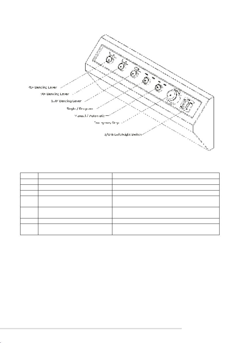
CONTROLS & SETTINGS
NO BUTTON FUNCTION
1 45° Bending Lever Used in setting bending degrees
2 90° Bending Lever Used in setting bending degrees
3 180° Bending Lever Used in setting bending degrees
4 Manuel / Automatic Allows to control the machine automatically or
manually
5 Emergency Stop Used when the machine should be turned off
6 Left/Right Key Ensures the machine to run in left or right direction
7 FootSwitch Ensures operation of the disc
8 Switchboard Includes automation system
45, 90 AND 180ºBENDING:
There are switch adjusting pins in three sizes on the bending disc. These pins are set
upon delivery of the machine. A bending degree is selected by the bending adjusting lever
attached in front of the machine. MAN-AUTO switch left side on the control board should be
moved to MAN position, and rotation direction should be checked. After these checks are
completed, hook bending operation is carried out in the machine. Is the switch pins are
replaced, the switch pin should be moved forward and backward through angle adjusting
grooves installed in edges of the bending disc to readjust, and thus a bending angle should be
set properly for hook bending (When the switch pin approaches the switch, the bending
degree decreases. When the switch pin move away from the switch, the bending degree
increases).
After setting operation is completed, the pin is attached to the spindle rim of the
bending disc, install the bending bush appropriate diameter of any steel plate to be bended on
the pin. Install one of other pins into one of the grooves on the bending disc, and install one of
proper bending balls on the pin to ensure a proper opening according to thickness of the steel
plate to be bended. Put of the steel plate to be bended on the machine, and one of the bending
pins into one of the grooves on the bending sledges. According to thickness of any steel plate
10
to be bended, steel plate of the bending disc should be installed to its front side over bending
sledges for safety to prevent it from moving and causing any injury during bending return.
The bending sledges are moved forward and backward by means of an adjusting wrench, and
it is ensured that the steel plate to be bended is aligned as length of the machine. Thus bending
operations should be completed. The machine should be moved to automatic position for
serial bending operations.
While the machine in Manual position, as long as the foot lever is pressed, the bending
disc of the machine rotates, and then stops at the time when the machine completes bending
operations and comes to standby position. While the machine is in automatic position, after
the foot lever is pressed and released once, the bending disc stops at the time when the
machine completes bending operations and comes to standby position. Further, while the
machine is in automatic position, the bending disc stops at the time the machine completes
bending operations, and the foot lever is held and pressed during return. When the foot lever
is released, it rotates in the return direction, and stops at the zero point.
To change foot, the bending change lever in its front side is moved to the position
shown in figure.
STIRRUP & SINGLE REBAR BENDING:
Single Bending:
The machine will bend single bar when “SINGLE” is chosen in the button. It will, for
example, bend only and only 45ºin every push to footswitch. The bending angle in Single
Bending could also be observed from the buttons, each time, the light inside the button will
appear once during bending.
Stirrup Bending:
In multiple stirrups bending, the SINGLE / PROGRAM button should be turned to
PROGRAM side. The program allows the operator to select the angles consecutively. Each
angle is selected by a single button push, and the next angle is selected by the same. The
operator should enter the angles he wants the stirrup to be bended. After the program is
selected and the angles are determined, the bending disc will turn to each angle consecutively
after each single push to FootSwitch. The memorized angles would be deleted by turning the
button to SINGLE once and back to PROGRAM side.
NOTE: After setting the machine, never run it in adverse direction. It may damage to all
mechanical parts.
10