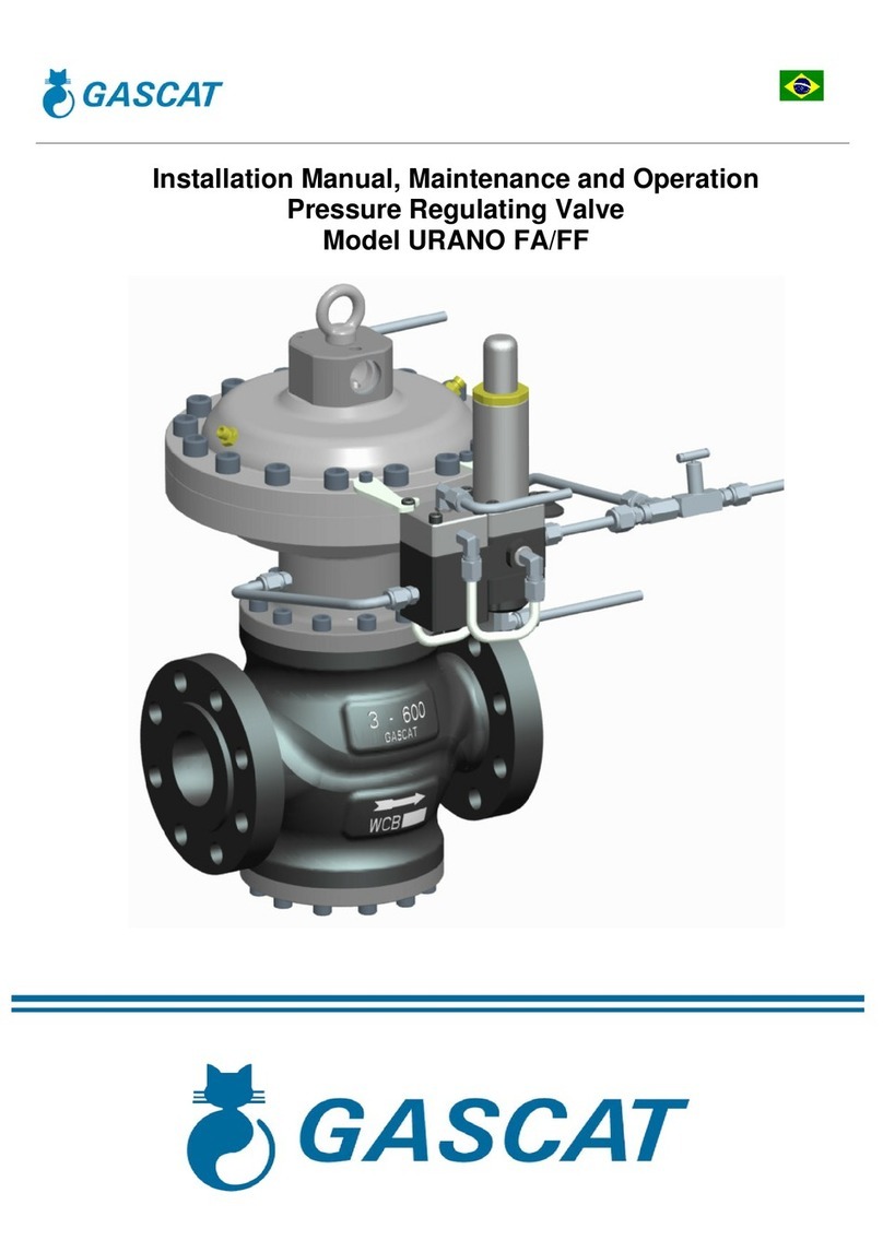
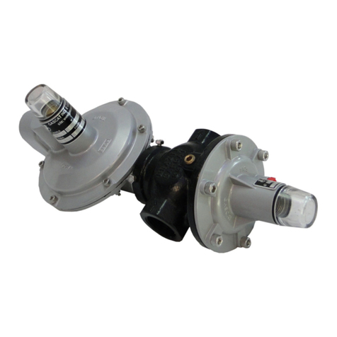
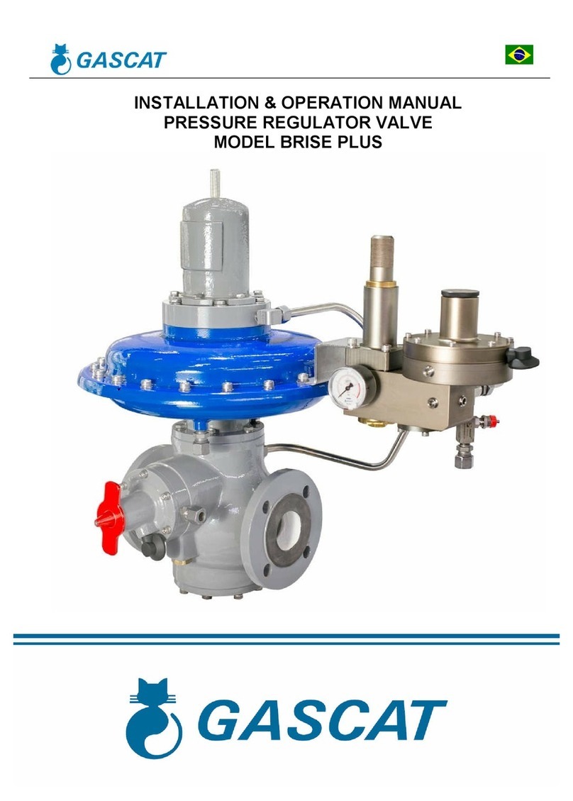
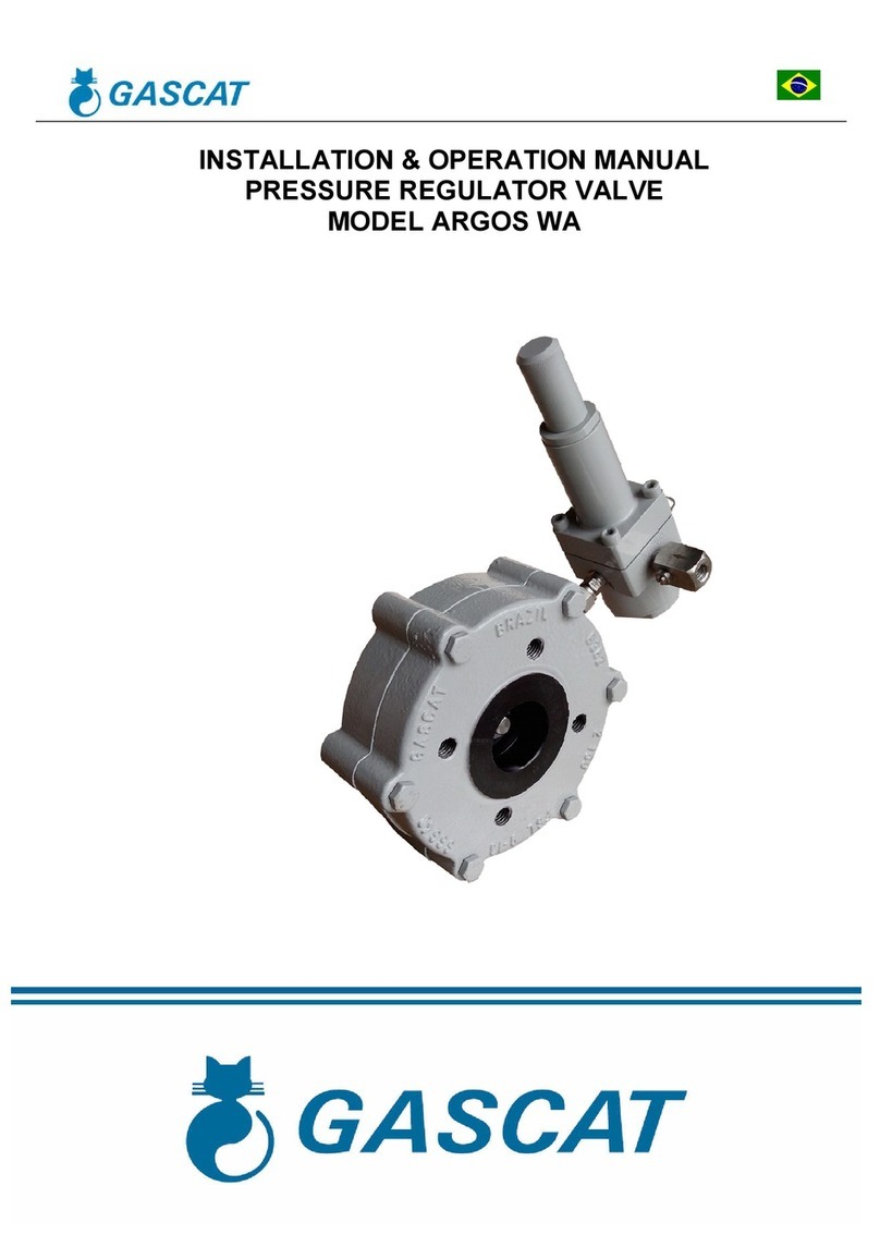
Gascat ARGOS Instruction manual

Installation, Operation & Maintenance Manual
Pressure Regulating Valve
Model ARGOS

Installation and Operation Manual
Argos - Pressure Regulating Valve MI-23
Elaborado Verificado / Aprovado CSQ Data Revisão Página
JJ
VBL JM 13/02/19 07 2 de 32
TABLE OF CONTENTS
1.0 GENERAL WARNING 3
1.1 PRE-COMMISSIONING INSTRUCTIONS 3
1.2 - HEALTH & SAFETY 3
1.2.1 - NOISE 3
1.2.2 - INSTALLATION 3
1.2.3 - OPERATION 3
1.2.4. MAINTENANCE 4
2.0 INTRODUCTION 4
2.1 SCOPE 4
2.2 DESCRIPTION 4
2.3 SPECIFICATIONS 4
2.3.1 AVAILABLE CONFIGURATIONS 4
2.3.2 AVAILABLE CONNECTIONS 4
2.3.3 TEMPERATURE LIMITS 5
2.3.4 COEFFICIENT OF FLOW (CV) 5
2.3.5 WEIGHTS 5
2.3.6 MAXIMUM WORK PRESSURE 5
2.3.7 SET POINT PRESSURES 6
2.3.8 ACCURACY AND LOCK UP 6
2.3.9 SLAM SHUT VALVE SPRING (SET POINT) 7
2.3.10 ACCURACY AND LOCK UP 7
2.3.11 PRESSURE REGULATORS DIMENSIONS 8
3.0 - OPERATION PRINCIPLE 10
3.1 THE REGULATOR 10
3.2 REGULATOR - ACTIVE / MONITOR SYSTEM 11
3.3 PILOTS 12
3.4 FITLERS 12
3.5 SECURITY SHUT-OFF VALVE 13
4.5.1 PH ACTUATOR & H ACTUATOR 13
4.5.2 GENERAL RESET PROCEDURE 13
4.0 - INSTALLATION 15
4.1 FILTER 15
4.2 CLEANING 15
4.3 FLOW DIRECTION AND SYSTEM INTEGRITY 15
4.4 SENSING LINE 15
4.5 RECOMMENDED INSTALLATION SCHEME 16
4.5.1 SINGLE REGULATOR 16
4.5.2 ACTIVE / MONITOR SYSTEM 17
4.5.3 SYSTEM WITH TWO SSV AND ONE REGULATOR 18
4.5.4 WORKING MONITOR SYSTEM 19
4.6 COMMISSIONING AND START-UP 20
4.6.1 GENERAL RECOMMENDATIONS 20
4.6.2 COMMISSIONING (SINGLE REGULATOR - STREAM) 20
4.6.3 STAND BY LINE ADJUSTMENT 21
4.6.4 COMMISSIONING (ACTIVE MONITOR SYSTEM) 21
4.6.5 STAND BY LINE ADJUSTMENT (ACTIVE / MONITOR SYSTEM) 22
4.6.6 COMMISSIONING (WORKING MONITOR SYSTEM) 23
4.6.7 LIST OF RECOMMENDED TOOLS 24
5.0 TROUBLE SHOOTING 25
6.0 MAINTENANCE 26
6.1 RECOMMENDED REPAIR PARTS AND KITS 27
6.2 RECOMMENDED TORQUES 32

Installation and Operation Manual
Argos - Pressure Regulating Valve MI-23
Elaborado Verificado / Aprovado CSQ Data Revisão Página
JJ
VBL JM 13/02/19 07 3 de 32
1.0 GENERAL WARNING
1.1 PRE-COMMISSIONING INSTRUCTIONS
It should be clearly understood that with these information hereby presented in the instructions for commissioning that
follows, there is no intention to revenue or replace the instructions determined by any other organ or institute and should be
done reference to the relevant Standards and/or recommendations existents over this subject.
Before any commissioning, it is understood that the execution of proper purification and cleanness procedures that
shall be observed and all instructions about pressurization and standard of safety and health, should be strictly observed.
The valve suppliers recommendation, as for example, open slowly and open very slowly should be strictly observed.
1.2 HEALTH & SAFETY
Regulators, valves and other pressurized components that contain toxic gases, flammable or other hazardous products,
are potentially dangerous if not operated and maintained correctly. It is mandatory that all users of this equipment are
properly educated and guided on potential dangers, and get assured that the personnel responsible for their installation,
testing, commissioning, operation, and the plant maintenance are competent to perform these tasks. Instruction manuals
are provided for the operators’ guidance, but it is assumed that they have a basic level of knowledge. If there are any
questions or ambiguities that affect the proper procedures ask Gascat Ind. e Com. Ltda., who will be pleased to advise or
provide the relevant service or instruction. TAKE NO RISKS. Our phone, fax and e-mail numbers are the following:
Gascat Indústria e Comércio Ltda.
Rodovia SP 73, 1141 - Indaiatuba / São Paulo.
CEP 13347-990
Phone: 55 19 3936-9300
Fax: 55 19 3935-6009
Email: vendas@gascat.com.br / sales@gascat.com.br
The items that follow, although not exhaustive, provide guidance on possible sources of danger to health and safety.
1.2.1 NOISE
Regulators, valves and pressure reducers can generate high levels of noise, which may be harmful to persons exposed
to them for long periods. Users should ensure that adequate precautions are taken in order to provide health safety to
employees and/or to third parties according to the Standards and recommendations in force.
1.2.2 INSTALLATION
All equipment, piping and vessels are designed to withstand mechanical stress, such as torque and bending moments
in addition to internal pressure. However, maximum care must be taken during installation, not to impose excessive stress,
which may cause cracks that may result in a serious break when the regulator is put into operation. Excessive stress can
also be caused because the valve cannot sustain piping stretches, which require adequate support.
All regulators, shutoff valves, relief valves, etc., must be installed with the correct flow direction.
Impulse lines are important components of any control system, and their proper installation is essential, with no isolation
valves.
Impulse lines shall be properly supported to reduce excessive vibration, which may cause fatigue rupture. They shall
also be positioned so that they cannot serve as hand or footrest. Impulse lines should be slightly inclined so that liquid and
condensates drain towards the main pipe.
When necessary (in underground facilities or indoor area) a ventilation pipe shall be installed from the threaded hole
(ؼ” NPT), found in the valve bell or in the diaphragm housing, and extended to a safe and ventilated location, with the
vent output protected to prevent it from inlet of rain water and insects that can obstruct ventilation.
Auxiliary systems shall not be changed or modified without knowledge of the operating conditions and the responsible
personnel permission.
1.2.3 OPERATION

Installation and Operation Manual
Argos - Pressure Regulating Valve MI-23
Elaborado Verificado / Aprovado CSQ Data Revisão Página
JJ
VBL JM 13/02/19 07 4 de 32
Depending on the regulator type, its valve may be positioned fully open. Consequently, when putting a regulator in
operation the shutoff valves shall be opened slowly, so that the regulator valve can assume its regulating position. If the
shutoff valves are quickly opened, the upstream pressure can pass through the regulator and over-pressurize the
downstream section of the main line.
All regulators, etc. shall operate with the regulation spring specified by the manufacturer. This is particularly important
when operating relief valves or shutoff valves, since incorrect springs may prevent a relief valve to open and a shutoff valve
to close.
Precautions shall be taken to prevent water inlet through breathing and ventilation openings.
1.2.4 MAINTENANCE
Regulators and valves contain gases under pressure, sometimes at a much higher pressure than the atmospheric
pressure. Before attempting to investigate a problem, or perform maintenance work on an equipment, it must be safely
depressurized. Furthermore, as many gases may be flammable, toxic, corrosive, or hazardous, it may be necessary to
purge the system with an inert gas, such as nitrogen. Special precautions are required for operation with gases such as
oxygen or hydrogen chloride, and the user must ensure that proper procedures are implemented.
Eventually, it is not enough to isolate the high-pressure device, since high pressure can be retained downstream of the
isolation valves. Do not try to remove caps, plugs, etc, before the device is properly released. Even so, it is wise to
consider that high-pressure gas may be trapped when removing covers and plugs.
Most regulators use spiral springs as the charging device. It is important to reduce these springs loading by moving
their pressing plates backwards as much as possible. In some cases, the spring may contain some residual load, even
when it is relaxed to the limits of its housing.
2.0 INTRODUCTION
2.1 SCOPE
This manual has the objective to provide information of operation, installation and maintenance about the pressure
regulator model ARGOS manufactured by GASCAT.
2.2 DESCRIPTION
The pressure regulator model ARGOS is pilot operated type designed by Gascat engineering to assist different
applications. It has large utilization in the Gas Distribution.
Outstanding by simplicity of operation and handling, facility of maintenance due of few internal parts and the relation
cost-benefit.
2.3 SPECIFICATIONS
2.3.1 AVAILABLE CONFIGURATIONS
Active / Monitor System
Working Monitor System
Flow Limiter by Orifice Plate
2.3.2 AVAILABLE CONNECTIONS

Installation and Operation Manual
Argos - Pressure Regulating Valve MI-23
Elaborado Verificado / Aprovado CSQ Data Revisão Página
JJ
VBL JM 13/02/19 07 5 de 32
ND FLANGE ASME B16.5 FLANGE DIN 2634 / 2635
1” 150#RF / 300#RF
(Thread NPT Female only for 1’’) PN 25 / PN 40
2” 150#RF / 300#RF PN 25 / PN 40
3” 150#RF / 300#RF PN 25 / PN 40
4” 150#RF / 300#RF PN 25 / PN 40
Note: other diameters and connections should be previously consulted.
2.3.3 TEMPERATURE LIMITS
Operation temperature: -20°C to 60°C
Room temperature: -20°C to 60°C
The temperature limits given in this manual or in any applicable standard shall not be exceeded under any
circumstances, under risk of damage to the equipment, to the installation safety, and to the people involved in the
operation.
2.3.4 COEFFICIENT OF FLOW (CV)
ND CV KG
1” 13.5 420
2” 48 1500
3” 93 2900
4” 206 6400
NOTE:
1) We suggest considering a 20% safety margin on the calculated value.
2) When dimensioning an active-monitor system consider a 25% restriction in the CV/KG of both valves.
2.3.5 WEIGHTS
ND ARGOS ARGOS SSV
150# 300# 150# 300#
1” 11 11.5 - -
2” 15 16 30 31
3” 28 29 43 44
4” 42 44 58 60
NOTE:
1) Approximate weights given in kilograms (Kg)
2) Consider the body in carbon steel SA-216 WCB
2.3.6 MAXIMUM WORK PRESSURE

Installation and Operation Manual
Argos - Pressure Regulating Valve MI-23
Elaborado Verificado / Aprovado CSQ Data Revisão Página
JJ
VBL JM 13/02/19 07 6 de 32
150# 300# PN 25 PN 40
19 bar 51 bar 25 bar 40 bar
The pressure limits given in this manual or in any applicable standard shall not be exceeded under any circumstances,
under risk of damage to the equipment, to the installation safety, and to people involved in the operation.
2.3.7 SET POINT PRESSURES
Pressure regulators model ARGOS can use three pilot models for pressure control G80, G30F or G32F. The table
below presents the adjustment ranges of each model:
G80 PILOT
SPRING COLOR PART NUMBER RANGE
WHITE 01.50.21G 60 - 220 mbar
BLACK 01.50.67 170 - 320 mbar
SILVER 01.50.21 230 - 400 mbar
GRAY 01.50.24 350 – 1100 mbar
G30F PILOT
SPRING COLOR PART NUMBER RANGE
SILVER 01.49.61 0.7 - 2.8 bar
GREEN 01.49.65 2 - 5.5 bar
RED 01.49.34 4.5 – 14 bar
BROWN 01.49.33 7.0 - 18.3 bar
BLACK 01.49.59 14.0 - 32.0 bar
32F PILOT
SPRING COLOR PART NUMBER RANGE
BLACK 01.49.59 14.0 - 36.6 bar
2.3.8 ACCURACY AND LOCK UP
Pressure Regulator:
AC up to 2.5%; SG up to 5%

Installation and Operation Manual
Argos - Pressure Regulating Valve MI-23
Elaborado Verificado / Aprovado CSQ Data Revisão Página
JJ
VBL JM 13/02/19 07 7 de 32
2.3.9 – SLAM SHUT VALVE SPRING RANGE (SET-POINT)
SSV – ACTUADOR H
SPRING COLOR PART NUMBER RANGE
PURPLE 01.52.61 0.3 – 1.5 bar
RED 01.52.62 1.0 – 5.0 bar
YELLOW 01.51.54 4.0 – 11.0 bar
SSV – ACTUATOR PH
SPRING COLOR PART NUMBER RANGE
BROWN 01.52.64 10.0 – 16.0 bar
ZINCATED 01.52.25 14.0 – 38.0 bar
WHITE 01.52.36 28.0 – 60.0 bar
2.3.10 – ACCURACY AND LOCK UP
Pressure regulator: AC up to 2,5% / SG up to 5%
SSV: AG up to 5

Installation and Operation Manual
Argos - Pressure Regulating Valve MI-23
Elaborado Verificado / Aprovado CSQ Data Revisão Página
JJ
VBL JM 13/02/19 07 8 de 32
2.3.11 PRESSURE REGULATOR DIMENSIONS
DIMENSIONS (mm)
A (RF) B C
ND 150# /
PN16
300# /
PN25,
PN40
ANY
CLASS
ANY
CLASS
1” 184 197 222 230
2” 254 267 243 288
3” 298 317 318 340
4” 353 368 340 390
General Tolerance = ±2

Installation and Operation Manual
Argos - Pressure Regulating Valve MI-23
Elaborado Verificado / Aprovado CSQ Data Revisão Página
JJ
VBL JM 13/02/19 07 9 de 32
DIMENSIONS (mm)
A (RF) B C
ND 150# /
PN16
300# /
PN25,
PN40
ANY
CLASS
ANY
CLASS
2” 254 267 550 300
3” 298 317 620 331
4” 353 368 703 410
General Tolerance = ±2

Installation and Operation Manual
Argos - Pressure Regulating Valve MI-23
Elaborado Verificado / Aprovado CSQ Data Revisão Página
JJ
VBL JM 13/02/19 07 10 de 32
3.0 - OPERATION PRINCIPLE
3.1 THE REGULATOR
The pressure regulator Argos works by principle of drop pressure in the upper chamber (diaphragm of main valve).
In the flow absence the pressure regulator stays close, because the pressure in the upper chamber of diaphragm (feed
by the pilot), added to the spring force is superior to the pressure that acts below the diaphragm (inlet pressure).
The pilot, in this condition of flow absence, stays closed, because the outlet pressure added to obturator spring of pilot
is superior to the regulating spring force, and moves the obturator set upward, against the pilot seat, closing the pilot gas
passage.
In case of flow, the pressure in the sensing line start decreasing, causing the pilot opening because of the regulating
spring of pilot added to the pressure under its diaphragm. In parallel, the discharge pressure also decreases. In this
condition, occur the reducing of the pressure in the upper chamber of diaphragm of main valve. Then, the inlet pressure
become superior to the spring force of main valve added to the pressure in the upper chamber of diaphragm of main valve,
allowing that the main valve opens, releasing the gas to the process.

Installation and Operation Manual
Argos - Pressure Regulating Valve MI-23
Elaborado Verificado / Aprovado CSQ Data Revisão Página
JJ
VBL JM 13/02/19 07 11 de 32
3.2 REGULATOR - ACTIVE / MONITOR SYSTEM
In the active / monitor system, the regulator working principle is similar then previously explained.
The upstream regulator (monitor) keeps in the open position, because the pilot sensing line monitors the active
pressure regulator set point and, as its set point is lightly higher, the pilot keeps opened. The reason that this pilot stays
opened is due of pressure under its diaphragm that added to the obturator spring that are lower than the regulating spring
force that moves this obturator set downward opening the pilot.
With this, the pressure in the diaphragm upper chamber in the monitor regulator keeps lightly lower than the inlet
pressure allowing the valve stays in the open position during normal process service conditions.
In case of active regulator fail that results in increase in outlet pressure, the pilot of monitor regulator start closing up to
achieve the set point of this pilot, and then the monitor regulator can assume the control of pressure reduction in the
system. From this moment, the working principle of this valve is similar then the active regulator.
The configuration of assemblage active / monitor is highly utilized in the gas distribution and transmission. This
configuration is normally adopted when the difference between the inlet and outlet pressure is over than 16 bar and the
strength pressure test in the pipe and other components upstream the regulator is inferior than the inlet pressure as
specified, for example in the standard DIN EN 12186, in this case the objective of use of monitor regulator is to increase
the system safety level.
However, is important to remember that this is a recommendation of DIN EN 12186 and that there are other standards
that specifies different conditions of use of active / monitor system.
The active / monitor system consists of utilization of two pressure regulators in series being one of them called active
that will be in operation (regulating the pressure) under normal process service conditions and one monitor regulator that
should stay totally open under normal process service conditions, and will assume the pressure regulating in case of active
regulator fail.

Installation and Operation Manual
Argos - Pressure Regulating Valve MI-23
Elaborado Verificado / Aprovado CSQ Data Revisão Página
JJ
VBL JM 13/02/19 07 12 de 32
3.3 PILOTS
The pressure regulator model ARGOS manufacture by GASCAT use pilot model G80, G30F or G32F depending of the
desired set-point.
This pilot is responsible by the control of feed pressure of main regulator actuator and by consequence of the pressure
regulator aperture.
The set pressure of the G80 pre pilot It should be 0.8 bar more than the desired outlet pressure, for example if you
want to adjust the valve in 0.5 bar, you must adjust your pre pilot in 1.3 bar. You can verify the pre pilot adjusted pressure
in the pressure gauge connected to the pre pilot.
3.4 FILTERS
The GASCAT pilot blocks, consisting of a pilot and pre-regulator always have a mechanical barrier against solid
impurities; this barrier comprises a polypropylene filter element of 10-micra filtration grade.
This barrier is intended to prevent that solid contaminants contained within the pipework can clog or damage the
internal parts of pre-regulator and of the pilot. However, it is important to note that this filter does not replace the
filtration system that shall be provided in preliminary steps to pressure regulating to leave the fluid clean and
according to correct operating conditions. This filter is designed to serve as the last barrier to solid contaminants.
The ARGOS pressure regulators can be provided with an F-10 filter mounted in separate from the pilot unit, or in a
compact version, with the filter element already coupled to the pre-regulator.
G30F/G32F PILOT
G80 PILOT

Installation and Operation Manual
Argos - Pressure Regulating Valve MI-23
Elaborado Verificado / Aprovado CSQ Data Revisão Página
JJ
VBL JM 13/02/19 07 13 de 32
3.5 SECURITY SHUT-OFF VALVE
3.5.1 PH ACTUATOR & H ACTUATOR
The slam shut valve has two actuators models, one with a diaphragm (for pressures 1.0 – 11.0 bar) and other with a
piston (for pressures 10.0 – 60.0 bar).
Mechanism consists in a shaft (stem) and spheres collar monitoring the outlet pressure. In case of outlet pressure
increase or decrease, the external bush will move up or move down, allowing the spheres running out of channel and the
main shaft moves according to the force exerted by closing spring to close the valve against the seat, shutting downs the
gas totally tight (see the picture with the two conditions).
After reestablishing to the normal service condition operation it is necessary to reset manually the slam shut valve.
- Position 1: Shutting by increase pressure
- Position 2: Balanced mechanism
- Position 3: Shutting by decrease pressure
3.5.2 – GENERAL RESET PROCEDURE
To reset the valve to the open position (ready to work), the sensing line should be connected in the actuator
chamber .
Position 1
Position 2
Position 3

Installation and Operation Manual
Argos - Pressure Regulating Valve MI-23
Elaborado Verificado / Aprovado CSQ Data Revisão Página
JJ
VBL JM 13/02/19 07 14 de 32
3.5.2.1 – PROCEDURE TO RESET VALVE IN CASE OF OVER PRESSURE
1. Adjust the pressure of sensing line around 10-15% below under the set-point.
2. Use the by-pass valve to equalize the internal pressure of the valve.
3. Pull up the actuator stem until the upper position using the cap.
3.5.2.2 – PROCEDURE TO RESET VALVE IN CASE OF UNDER PRESSURE
1. Adjust the pressure of sensing line around 10-15% above the over set-point.
2. Use the by-pass valve to equalize the internal pressure of the valve.
3. Pull up the actuator stem until the upper position using the cap
3.5.3 – SHUT-OFF RESET & INTEGRATED BYPASS PROCEDURE
To reset the shut-off, it is necessary to equalize the pressure before and after the shutter. However it is
necessary to use the integrated bypass in the reset lever. See below how to proceed:
When there is a lock, the position indicator will be indicated in closed position (according the picture). Then
it is necessary to use the cap screwing it to pull up the shaft (according the picture). After connecting the cap in
the actuator stem, the user should pull up the cap and to move the reset lever at the same time (according the
picture). The reset lever will move 20% of course, there is a resistance (because the differential pressure
between the inlet pressure and the outlet pressure) until the pressure before and after the shutter to be the
same.
The SSV is supplied in the closed position and with the actuator of under pressure blocking disarmed. The
springs for over and under pressure blocking are adjusted in Gascat.
Position Indicator
(closed position)
Reset Lever
Cap

Installation and Operation Manual
Argos - Pressure Regulating Valve MI-23
Elaborado Verificado / Aprovado CSQ Data Revisão Página
JJ
VBL JM 13/02/19 07 15 de 32
4.0 - INSTALLATION
4.1 FILTER
We recommend the installation of a cartridge type filter, with 5 micra filtration degree, as close to the regulator inlet as
possible, without being joined flange to flange, because the filter installed immediately upstream of the regulator may
produce turbulence and cause disturbance in the pressure control of the regulator. Care in filter installation is essential for
the regulator proper operation, as any existing particles in the pipe may take lodge between the seat and the shutter,
damaging them and causing feedthrough.
4.2 CLEANING
Check the pipe cleaning before valve installation. We advise a complete purge of the line with nitrogen or compressed air.
4.3 FLOW DIRECTION AND SYSTEM INTEGRITY
Before proceed with installation it is necessary to verify if:
1) The equipment is with perfect conditions or have evidences of damage in function of handling during the
transportation; in case of damage do not install it before contacting GASCAT.
2) The space foresee for access and installation of equipment is adequate, including future maintenance.
3) The installation was designed to support the charge (weight) of equipment.
4) The inlet and outlet connections where the regulator will be installed are perfectly aligned.
5) All sensing line needed in the pipe downstream the equipment were supplied and are respecting the
recommended dimensions by the manufacturer.
6) It was foresee pressure gauge or other pressure indicator to allow correct setting during the commissioning and
operation.
7) It was foresee venting line between the pressure regulator and first slam shut to assist the operator during the
start up.
8) Flow direction of pressure regulator is in the adequate position.
4.4 SENSING LINE
The correct positioning of sensing line in the pipe is essential for correct working of pressure regulator, because of
this install the sensing line of pilot distant of 5 times the nominal pipe diameter in a stretch free of obstruction, in a pipe
size where the gas velocity do not exceed 25m/s (considering the lower outlet pressure and maximum flow).
To obtain better pneumatic signal, utilize tubings D.E ½” in stainless steel AISI 316 to connect the sensing line in
the process.
In order to avoid accumulate particles and condensates in the sensing lines it is recommended to install it with
inclination of 5%~10% to allow flow it to the main pipe.
Check the welded connections in the pipe to avoid it clogged, without any welding residue that can affect the
pneumatic signal.
Do not install insulating valves in the sensing line of pressure regulators.
The pressure regulator model Argos needs only one connection to the process per valve, that is the sensing line of
pilot, independently of system configuration (active / monitor, working monitor and only active regulator). Exception
only for flow limiter that have two extra connections in the orifice plate.
The loading and discharge sensing lines are connected directly in the body.

Installation and Operation Manual
Argos - Pressure Regulating Valve MI-23
Elaborado Verificado / Aprovado CSQ Data Revisão Página
JJ
VBL JM 13/02/19 07 16 de 32
4.5 RECOMMENDED INSTALLATION SCHEME
4.5.1 SINGLE REGULATOR
1 – Inlet ball valve (or similar)
2 – Cartridge filter Metrius with 5 micron
3 – Inlet pressure gauge
4 – Slam shut valve with fail close actuator model GIPS-FC
5 – Pressure regulator model ARGOS
6 – Partial pressure relief valve CH Relief
7 – Outlet pressure gauge
8 – Vent valve
9 – Outlet ball valve (or similar)
Notes:
1) The position of sensing line can be inferior than 5 times if the project of installation had been analised and
approved by GASCAT engineering.
2) Other option of insllation is the utilization of a pipe in parallel to connect all sensing lines close of respective
equipment. Some advantages of this configuration are:
a. More practicity during maintenance.
b. Pneumatic signal with better quality (stable).
c. Reduction of damages in the tubings during maintenance and transport.

Installation and Operation Manual
Argos - Pressure Regulating Valve MI-23
Elaborado Verificado / Aprovado CSQ Data Revisão Página
JJ
VBL JM 13/02/19 07 17 de 32
4.5.2 ACTIVE / MONITOR SYSTEM
1 – Inlet ball valve (or similar)
2 – Metrius cartridge Filter – 5 micron
3 – Inlet pressure gauge
4 – Slam shut valve with fail close actuator model GIPS-FC
5 – Monitor pressure regulator Argos
6 – Pressure gauge
7 – Active pressure regulator Argos
8 – Partial pressure relief valve model CH Relief
9 – Outlet pressure gauge
10 – Vent valve
11 – Outlet ball valve (or similar)
Notes:
1) The position of sensing line can be inferior than 5 times if the project of installation had been analised and
approved by GASCAT engineering.
2) Other option of insllation is the utilization of a pipe in parallel to connect all sensing lines close of respective
equipment. Some advantages of this configuration are:
a. More practicity during maintenance.
b. Pneumatic signal with better quality (stable).
c. Reduction of damages in the tubings during maintenance and transport.

Installation and Operation Manual
Argos - Pressure Regulating Valve MI-23
Elaborado Verificado / Aprovado CSQ Data Revisão Página
JJ
VBL JM 13/02/19 07 18 de 32
4.5.3 SYSTEM WITH TWO SSV AND ONE REGULATOR
1 – Inlet ball valve (or similar)
2 – Metrius cartridge Filter – 5 micron
3 – Inlet pressure gauge
4 – Slam shut valve with fail close actuator model GIPS-FC
5 – Slam shut valve with fail close actuator model GIPS-FC
6 – Active pressure regulator model ARGOS
7 – Partial pressure relief valve model CH Relief
9 – Outlet pressure gauge
9 – Vent valve
10 – Outlet ball valve (or similar)
Notes:
1) The position of sensing line can be inferior than 5 times if the project of installation had been analised and
approved by GASCAT engineering.
2) Other option of insllation is the utilization of a pipe in parallel to connect all sensing lines close of respective
equipment. Some advantages of this configuration are:
a. More practicity during maintenance.
b. Pneumatic signal with better quality (stable).
c. Reduction of damages in the tubings during maintenance and transport.

Installation and Operation Manual
Argos - Pressure Regulating Valve MI-23
Elaborado Verificado / Aprovado CSQ Data Revisão Página
JJ
VBL JM 13/02/19 07 19 de 32
4.5.4 WORKING MONITOR SYSTEM
1 – Inlet ball valve (or similar)
2 – Metrius cartridge Filter – 5 micron
3 – Inlet pressure gauge
4 – Slam shut valve with fail close actautor model GIPS-FC
5 – Pressure regulator valve model ARGOS WORKING MONITOR (1st stage of pressure reduction)
6 – Pressure gauge
7 – Pressure regulator valve model ARGOS (2nd stage of pressure reduction)
8 – Partial pressure relief valve model CH Relief
9 – Pressure gauge
9 – Vent valve
10 – Outlet ball valve (or similar)
Notes:
1) The position of sensing line can be inferior than 5 times if the project of installation had been analised and
approved by GASCAT engineering.
2) Other option of insllation is the utilization of a pipe in parallel to connect all sensing lines close of respective
equipment. Some advantages of this configuration are:
a. More practicity during maintenance.
b. Pneumatic signal with better quality (stable).
c. Reduction of damages in the tubings during maintenance and transport.

Installation and Operation Manual
Argos - Pressure Regulating Valve MI-23
Elaborado Verificado / Aprovado CSQ Data Revisão Página
JJ
VBL JM 13/02/19 07 20 de 32
4.6 COMMISSIONING AND START-UP
4.6.1 GENERAL RECOMMENDATIONS
Before proceeding with the commissioning of equipment is important:
1) Verify if the equipment is correctly installed according to recommendations of this manual.
2) Close the inlet, outlet, by-pass valves, when applicable, of each stream.
3) Open the downstream vent valve of last regulator installed in the respective stream.
4) Certify that the Skid is depressurized.
ATTENTION:
* Under no hypotheses proceed with stream pressurization where the equipment is installed by
downstream valve.
* Under no hypotheses proceed with depressurization of stream where the equipment is installed
by the last valve located upstream the equipment, as filter drain, for example.
5) Verify if all connectors are properly installed before proceed with stream pressurization.
6) Verify if all equipment are installed adequate to the process conditions, through information provided in the
equipment nameplate.
7) Verify if the SSV (slam shut valve) is closed.
The SSV are released to the field calibrated, however, because of transport conditions and handling of
equipment its set point can be changed.
Then, it Gascat recommends to check the using external pneumatic source connected directly in
the actuator, before proceeding the stream pressurization.
The regulator model Argos is not supplied adjusted. It tends to preserve the life time of internal
parts. So that it is necessary to adjust the regulator prior to operation.
The configuration of Pressure Regulating Skid shall be according to DIN EN 12186 / NBR 12712 and other
standards where it will be installed.
4.6.2 COMMISSIONING (SINGLE REGULATOR - STREAM)
Utilizing as reference the scheme showed in item 4.5.1, proceed with the descriptive indicate for commissioning of
pressure regulator model ARGOS in a single stream, considering that all recommendations of item 4.6.1 were
already observed.
The procedure considers the utilization of slam shut valve model GIPS-FC GASCAT as safety device.
1) Close the vent valve.
As the slam shut valve is closed it is necessary to utilize the vent to simulate a low flow and then proceed with
regulator adjustment before align the stream.
2) Verify if the regulating spring of pilot is with no charge (with no charge).
Releasing the spring the valve will stay closed during pressurization.
3) Verify if the restrictor installed in the pilot inlet, loading sensing line, is opened between 30%~70%.
4) Open SLOWL AND GRADUALLY the inlet ball valve of Skid, or when the skid is adopted of by-pass in the
ball valve utilize it to pressurize the stream.
5) As there is no pressure upstream the regulator the slam shut valve is blocked (fail close type). Keep the by-
pass or push button (located in the SSV body) to pressurize the line between the slam shut valve and the
pressure regulator.
Table of contents
Other Gascat Control Unit manuals
Popular Control Unit manuals by other brands
Redbusbar
Redbusbar CircuitSpy 80 Installation and operation manual

Bodine
Bodine 1865 Instructions for installation and operation

Nero
Nero Radio 8113 IР65 manual

Wenglor
Wenglor BB1C5 Series operating instructions
Siemens
Siemens FMT-A-ADPT installation instructions

Allen-Bradley
Allen-Bradley CENTERLINE 1500 user manual

