Albixon ALBISTONE G1 BENEFIT User manual

Skimmer pools
ALBISTONE®
G1 BENEFIT
G1 PLUS
Version: 12/10/2020 / Update: 31/07/2021
L. V.
Preparation for construction
www.ALBIXON.com

2/ ALBISTONE®G1 BENEFIT/G1 PLUS Skimmer Pools
Contents
1.
If you require any additional information, please do not hesitate to
contact our customer helpline. We are here for you.
Customer helpline: 477 07 07 11
www.ALBIXON.com
1. Contents 2
2. Surveying and Excavation 3
3. Levelling the Bottom of the Excavation and Drainage of the Foundation Slab 8
4. Concreting of the Foundation Slab 10
5. Notification of Readiness for Construction 11
6. Placing the Pool Shell and Installation of the Pool Technology 12
7. Bracing the Pool 13
8. Concreting around the pool 14
9. Making the Base Plate for the Final Surface 16
10. Form 20
11. Electrical Wiring 22
12. Notes 29

ALBISTONE®G1 BENEFIT/G1 PLUS Skimmer Pools / 3
2.
Surveying and excavation
Swimming pool
Techn.
shaft
For the correct dimensions of the excavation, always refer to the diagrammatic drawing that is part of the
contract for work.Have a construction expert confirm in writing that placement at the intended location
is feasible from a constructional point of view and that it does not conflict with already installed utility
lines. The location of the pool must be in accordance with ČSN 33 2000-7-702.
1. Layout of the Pool
Excavation Width and Length for the Pool
The width and length of the excavation for the pool, for the pool placed by a crane = +500 mm on
each side counted from the outer dimension of the pool. These dimensions are shown as points
S1 and L1 in the images below.
Excavation Width and Length for Technology Shafts
Width and length of excavation for technology shafts = +600 mm from the outer diameter of the
shaft, or its outer width and length.
Example: Outer shaft diameter 1265 mm
Excavation dimensions 1865 x 1865 mm
Plan view of excavation for the pool and technology shaft (in mm)
1. Layout of the Shape of the Pool.
2. Excavation Depth.
3. Preparations for Placement of Miscellaneous Technology.

4/ ALBISTONE®G1 BENEFIT/G1 PLUS Skimmer Pools
Plan view of the excavation for a pool with a counterflow shaft
2.
Foundation slab
Swimming pool
Excavation
Technology wall
Shaft
to be placed so as not to interfere with the
concrete of the foundation slab
Disconnecting shaft
If the technology wall is placed higher than the water
level in the pool, it is necessary to create a disconnect-
ing shaft at the lowest point of the piping
counterflow shaft
Connection between the counter-
flow shaft and the pool indicated
min. 500 mm
Surveying and excavation
L pool length 4000 mm 6000 mm 8000 mm
L1 outer length of the pool 4250 mm 6250 mm 8250 mm
L2 foundation slab length 4700 mm 6700 mm 8700 mm
L3 excavation length 5250 mm 7250 mm 9250 mm
S pool width 3000 mm 2700 mm 3450 mm
S1 outer width of the pool 3250 mm 2950 mm 3700 mm
S2 foundation slab width 3700 mm 3400 mm 4150 mm
S3 excavation width 4250 mm 3950 mm 4700 mm
CSD dimensions of the excavation for the
counterflow shaft
1050 mm
PPL 1650 mm
ST dimensions of the excavation for the
technology shaft
for shaft diameter 1200 mm ST = 1 865 mm
for shaft diameter 1500 mm ST = 2 165 mm
layout of the pool shape
Subject to the type and size of the pool, mark (with sand, lime) the space for the pool. All measure-
ments and determination of the location of the pool should be carried out with the greatest care and
with regard to finishing works on the pool (paving etc.).

ALBISTONE®G1 BENEFIT/G1 PLUS Skimmer Pools / 5
2.
SD
2. Excavation Depth – Calculation.
Determine the depth of the pool excavation and of the excavation for placing the technology shaft
according to the calculations below. First determine the total depth of the pool excavation. The depth
of the excavation for the technology shaft (counterflow shaft) should be determined afterwards. The
height of the step (E) for the correct placement of the technology shaft should be determined at the
end. Please remember to account for the dierence from the raised terrain (U). The value “U” directly
addresses the final height of the complete construction of the pool; therefore it is necessary to take
into account all the construction steps performed subsequently (raised paving, recessing or raising
the pool, etc.).
The upper edge of the technology shaft should be set to at least 40mm (F) above the planned final
surface around the pool (make sure it does not collide with the travelling front of the roof). This is due
to the need to protect the shaft from rainwater. If you do not want to have the shaft elevated above
the final surface level, adequate drainage of rainwater must be provided around the shaft. The shaft
must not be located where the future rails for the roof will be installed. The bottom of the shaft is
intentionally kept without thermal insulation so that the shaft is naturally ‘heated’ in the winter from
the soil below.
A1 gravel bed with drain pipes 200 mm
A2 concrete foundation slab with a rebar mesh 200 mm
B bottom insulation (extruded polystyrene) 30 mm
C1 pool bottom thickness 8 mm or 6 mm
C2 pool depth subject to the pool type
D total depth of the technology shaft/counterflow shaft technology shaft = 1213 mm
counterflow shaft = 796 mm
E dierence in elevation between the pool foundation slab and the
shaft foundation slab
(H + F) - (A1 + A2 + D)
F elevation of the technology shaft specified by the manufacturer 40 mm
G concrete plus gravel (gravel 50 mm; concrete 100 mm) 150 mm
H pool excavation depth A1 + A2 + B + C1 + C2 + (±U)
SD shaft excavation depth (D - F) + G + (±U)
U thickness of paving/stone carpet/pool recess subject to the type
Surveying and excavation

6/ ALBISTONE®G1 BENEFIT/G1 PLUS Skimmer Pools
2.2. Surveying and excavation
Excavation and Securing the Perimeter Walls.
Excavation and securing of the perimeter walls of the pit (if necessary because of the geological conditions)
should be carried out exclusively by a specialized company. The excavated soil can be used for landscaping
around the pool; you can count on the majority of the soil being used this way. This means there is no need
to dump the soil. Landscaping around the pool refers to the pool as a new structure; not always necessary.
The aforementioned data and calculations apply to the standard location of the technology shaft –
see plan view of excavation.
Note:
Along with the earthworks and excavation, consider connecting the pool to the sewage and rainwater
system on the premises. This will enable the drainage pump and pool technology to be connected
directly to the drainage, which gives you more comfort in pool maintenance, for example, when
draining water from the filter, etc.
The following types of technology shafts may be included in the scope of the con-
tract for work:
Technology shaft with cover for installation of filtration (Ø 1200, height 1200 mm)
Technology shaft with cover for installation of filtration and counterflow (Ø 1500, height 1200 mm)
Technology shaft with cover for counterflow installation (1200 x 600 x 800 mm) = L/W/H
Important notice:
The contractor is responsible for securing the excavation walls.
Ø 1520
1360
1250
756
650
Ø 1220
TECHNOLOGY SHAFT
FOR FILTER INSTALLATION
TECHNOLOGY SHAFT
FOR FILTER AND
COUNTERFLOW INSTALLATION
TECHNOLOGY SHAFT
FOR COUNTERFLOW INSTAL-
LATION
Ø 1220
Ø 1265
Ø 1520
Ø 1600
Ø 1220
Ø 1170
Ø 1520
Ø 1470
1250
1200
1240
1360
D=796
788
D=1213
1205
D=1213
1205
40
40
40

ALBISTONE®G1 BENEFIT/G1 PLUS Skimmer Pools / 7
2.
Preparations for Placement of Miscellaneous Pool Technology.
Another possible location of the technology is oered by using the ALBIXON technology wall, in its own
dedicated shaft or in any other place (service room, garden house…). The pool technology should be placed in a
room with limited access (protected against unauthorized persons or children), where the ambient temperature
does not exceed 40 °C and where the ambient humidity is suitable for the needs of electrical components.
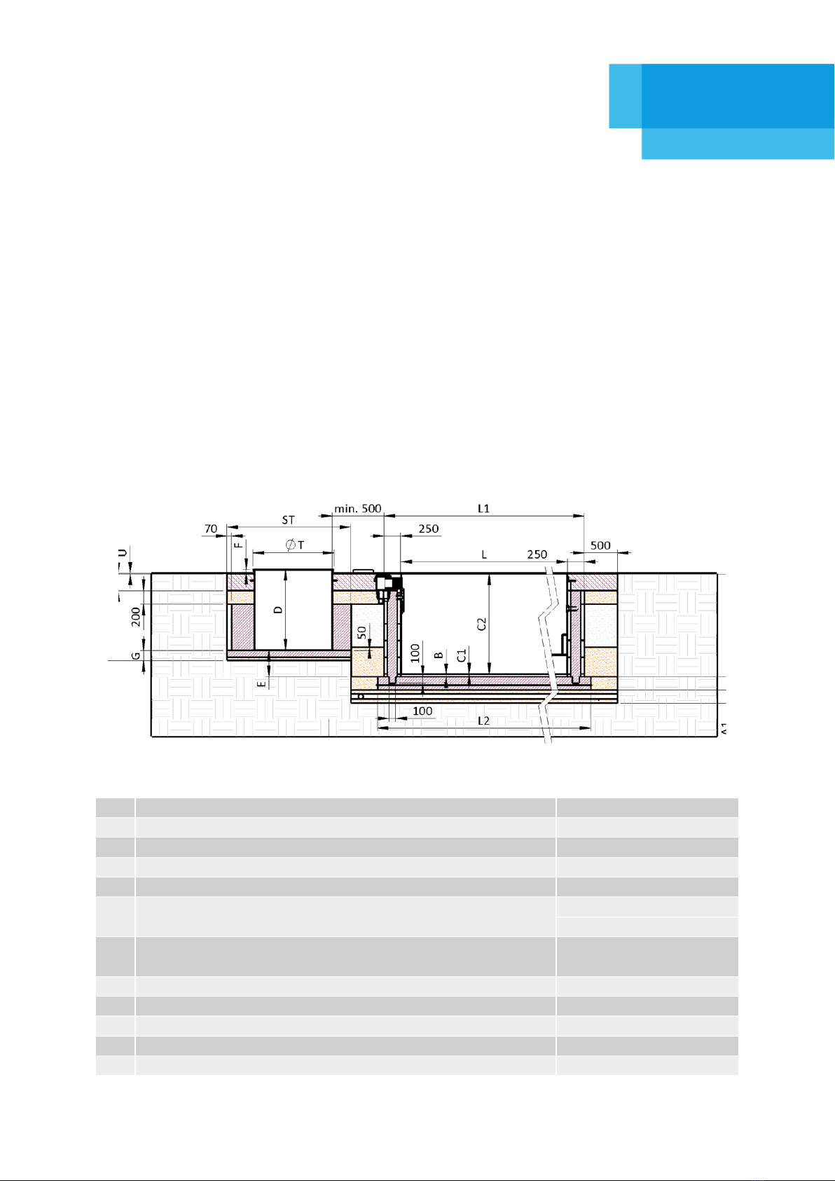
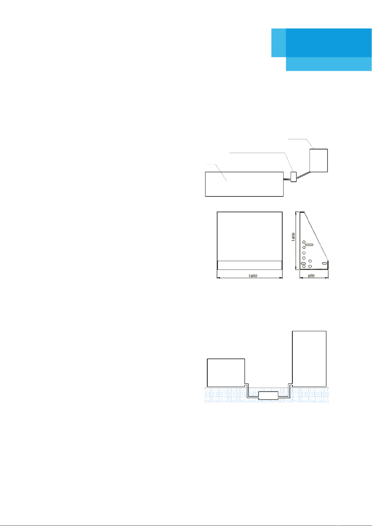
Where the technology is placed above the water level in
the pool, a maintenance (disconnecting) drain shaft should
be created. Maintenance shaft for convenient disconnection
of fittings. The disconnect at the lowest point must enable
draining all water from the shaft system used to drain water
fromthepipingfor winter. Thedimensions ofthe maintenance
shaft should be of at least 500 x 500 mm (subject to the
depth) and the depth should be adequate to the pipe route,
however always allowing for the convenient disconnection of
the pipes and discharge of water. For the location of the disconnect fitting, see the picture. The disconnect must
be placed at the lowest point of the piping.
Technology wall (left, right) – a technological unit designed to be
placed in a service room or in other suitable garden structure. The
wall must be placed on a horizontal and sufficiently rigid base. On the
side of the outlets (left or right), it is necessary to leave at least 500 mm
of space for connections and further handling. To connect the pool
technology and the pool and – if applicable – external heating, make
sure to prepare pipeline routes and penetrations of the appropriate
size (pipe Ø + insulation) into the technology installation space. This
also applies to technology that is installed atypically.
Install the counterflow device separately in the counterflow shaft or in the technology shaft. The counterflow
shaft should be positioned so that the counterflow pipe from the shaft is aligned with the pool axis and runs towards
the outlets of the counterflow body placed on the pool shell. This is to achieve the lowest power losses. The
maximum distance from the exterior contour of the pool shell is 2000 mm. If the counterflow is not aligned with
the axis of the pool shell, its performance will be diminished.
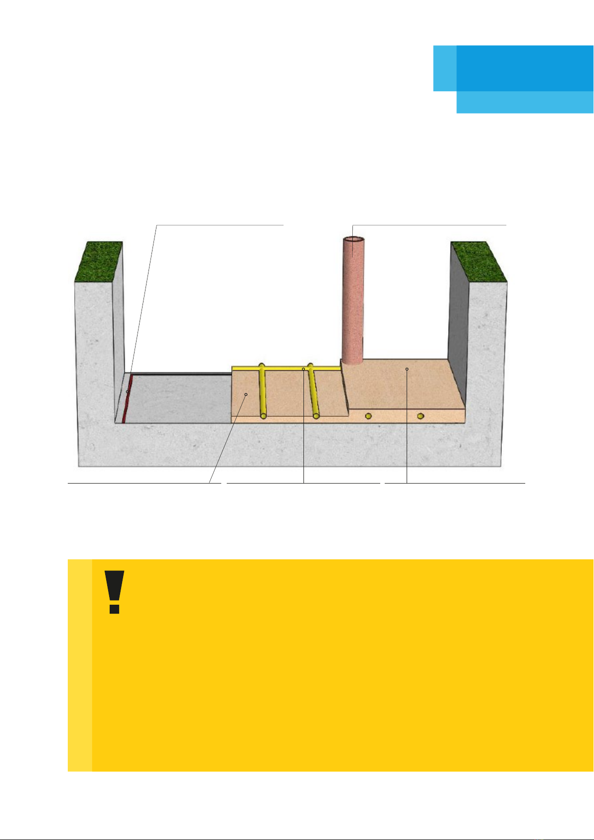
Heat pump – to connect the pool technology and the heat
pump, it is necessary to create routes for laying the connecting
pipe (excavation width 200 mm at minimum, pipe slope 1.5 °
along its entire length towards the shaft). To connect the heat
pump and the technology wall, it is necessary to place the
disconnectors for water discharge in the maintenance drain
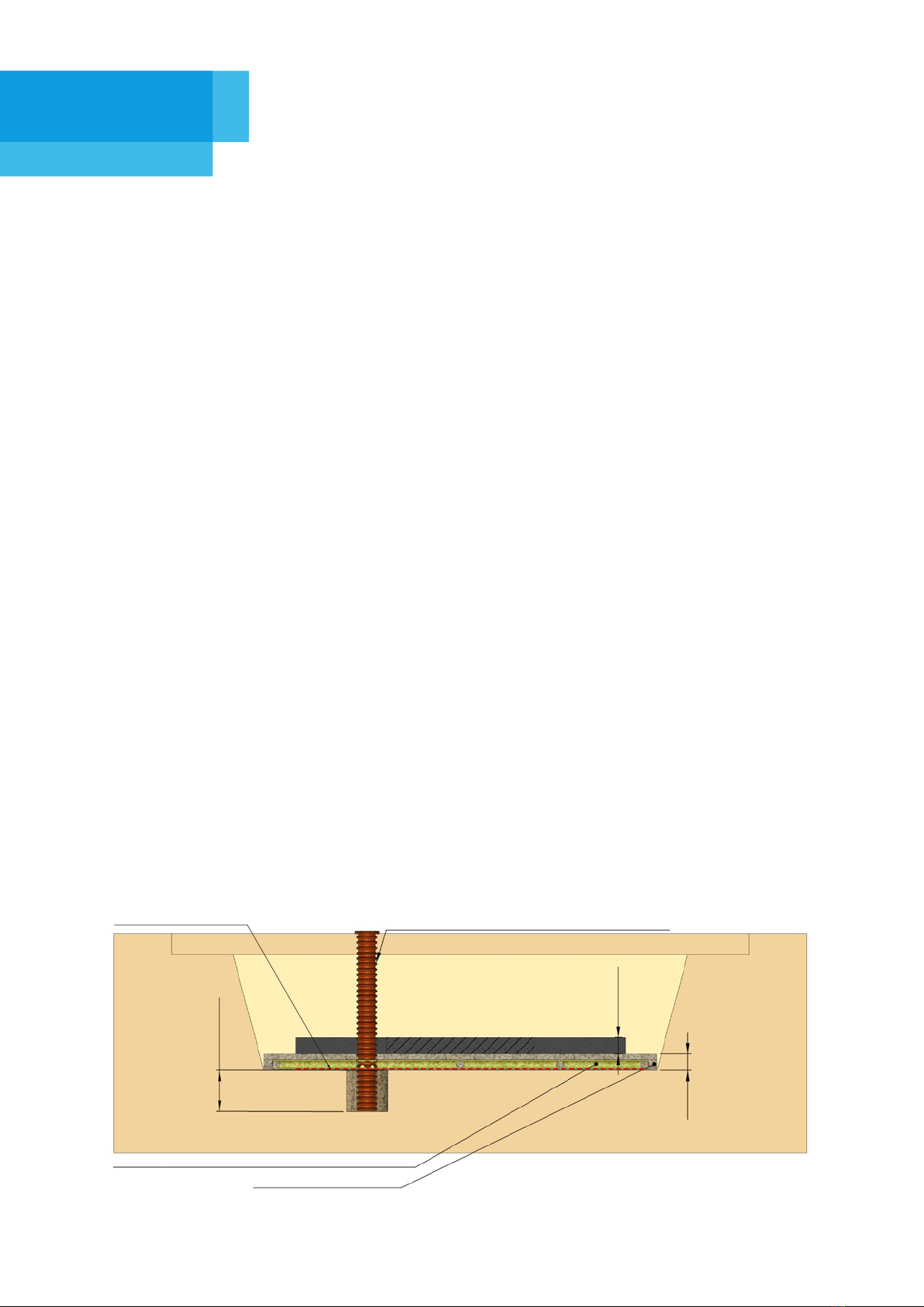
shaftat thelowest pointof thepipe. Theheat pumpfoundation
slab must be suciently firm and level (a concrete foundation
150mm high with floor plan dimensions that exceed those of
the heat pump by at least 40mm on each side). Install the heat pump in a spacious and sunny location with good
ventilation. Its position must allow for smooth air circulation; see the instructions for the respective heat pump.
During its operation, the heat pump may produce a considerable amount of water condensate. This needs to be
accounted for and drainage must be provided. Ensure that after installation the device is in an upright position
without any tilt. Do not install the device in places with the presence of contamination or corrosive gases, or where
dirt or fallen leaves collect. The place where it is installed must not be near flammable or explosive environments
with usual fire hazards. Observe distances from obstacles, always in accordance with the respective heat pump
manual. Install the heat pump at least 3500 mm from the edge of the pool (according to ČSN 33 2000-7-702)
and up to 7500 mm from the pool technology and with a vertical dierence of up to 1000 mm between the
water level in the pool and the bottom edge of the heat pump. This installation does not result in an excessive
decrease in the performance of the circulation pump and does not cause heat loss in the longer piping.
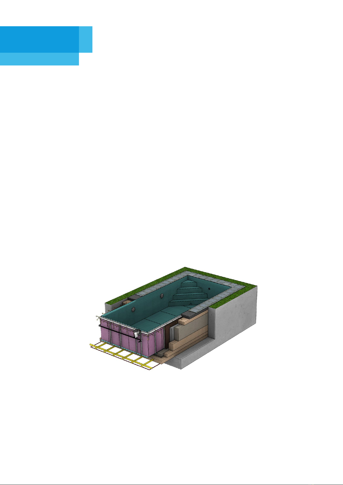
Swimming pool
Technology wall
Maintenance shaft for convenient
disconnection of fittings. Discon-
nection at the lowest point must
drain all water from the system.
Technology
shaft/wall
Heat
pump
Disconnecting
shaft
Surveying and excavation

8/ ALBISTONE®G1 BENEFIT/G1 PLUS Skimmer Pools
3.
1. Installation of earth strip and drainage set – 1st Stage.
An earth strip in accordance with the applicable standards must be installed at the bottom of the excavation.
For more details on electrical wiring, see the Electrical Wiring section.
The foundation slab must be permanently drained. For proper drainage of the foundation slab, it is necessary
to install drainage piping under the foundation; the piping should be connected to a drainage set (for drainage
pump shaft + drainage pump permanently connected to a power supply, see the following paragraph).
Ask your construction company for the ideal design of draining the pool foundation slab and any shafts,
according to the local geological conditions. Be sure, though, to account not only for groundwater but also
for rainwater, which may have equally negative eects on the pool shell as a whole, such as groundwater.
`
Drainage pump shaft – a pipe
with a diameter of approx. 300 mm placed
vertically next to the foundation slab. Pour gravel
with an 8-to-16-mm grain size onto the bottom
of this pipe. There must be a height dierence of at
least 500 mm between the gravel and the final
level of the pool foundation slab. The drainage
pump shaft serves as a sump for collecting
groundwater and rainwater. It must be provided
with a submersible pump. This pump must
trigger automatically when the water level in the
shaft rises and must be permanently connected
to the power supply via an underground cable.
The supply cable must run from the house
switchboard, and yet it must not be connected
through the switchboard in the technology
shaft. The pumped water must flow out of the
pool area and must not return under the pool
(see note on page 6 regarding the sewage and
rainwater system).
2. Backfilling with Gravel and Drainage Piping Installation, 2nd Stage.
Spread gravel with an 8–16mm grain size to form a layer about 100 mm thick the bottom of the
excavation. The 80-mm drainage piping is to be laid in the gravel layer, sloped down towards the
water outlet point (drainage pump shaft). The drainage pipe must be laid with a minimum slope of 1%.
In the layout, the mutual distances between the drainage pipes must not be greater than 800 mm.
All drainage pipes must be covered with a special geotextile before being overlaid with gravel and
concrete
Shaft
Earth wire
diameter of
8mm
Earth strip FeZn
30x4
For pools over 8 metres long – add
a “middle” guide for the earth strip
FeZn 30x4.
The measured earth resistance must
comply with the applicable standards
and regulations.
Levelling the Bottom of the Excavation
and Drainage of the Foundation Slab

ALBISTONE®G1 BENEFIT/G1 PLUS Skimmer Pools / 9
3.
3. Final Covering with Gravel, 3rd Stage.
Lay another approx. 100-mm-thick layer of gravel (grain size 8–16 mm) on top of the first layer of gravel with
the laid drainage pipes covered with geotextile. The gravel needs to be adequately compacted, but be careful
not to damage the drainage pipes.
2. Stage
Drainage pipes (placed after the
first gravel backfill; about half-
way through the total layer of
200mm, covered with geotextile)
3. Stage
Final gravel backfill
(up to 200 mm in total)
Important notice:
Drainage of the foundation slabs is an essential part of the construction preparation.
Rainwater and/or groundwater can cause quite extensive deformations of the pool shell;
therefore the foundation slab of the pool must always be properly drained. If the place for
installing the pool is in sloping terrain, or, after beginning the earthworks, it is found that it
has a clay subsoil (which means a higher probability of groundwater and its exercising of
pressure on the pool body), we recommend that you have a geological survey conducted
for foundation engineering. As a follow-up to its result, we recommend that you take
extended construction and drainage measures in relation to the target site, which will be
implemented outside the actual pool drainage system.
Damage to the pool caused by insufficient or inadequate preparation for construction is
not covered by the right arising from defective performance. Therefore, it is important to
monitor the construction company and its procedures continuously. We recommend
regular photo documentation of all the construction steps.
Levelling the Bottom of the Excavation
and Drainage of the Foundation Slab
1. Stage
earth strip FeZn 30x4
(around the pool excavation perimeter)
1. Stage
drainage shaft for pump
(located 500 mm below the excavation)
2. Stage
gravel backfill
(approx. half from a total height
of 200 mm)

10 / ALBISTONE®G1 BENEFIT/G1 PLUS Skimmer Pools
4.
1. Preparation of formwork for concreting.
Place the formwork on the compacted layer according to the floor plan dimensions on page 4. The formwork
height of 200 mm needs to be adjusted to the other height parameters – page 5. The formwork must be
level. (The specified flatness of the formwork is +/- 2 mm along the entire perimeter. Final inspection of the
backfilled excavation.
2. First Layer of Concrete.
Spread the first layer of concrete into the prepared formwork up to one-third of its height. The reinforcement
will be placed on this layer.
Use C16/20 grade concrete for concreting the foundation slab.
3. Installation of rebar meshes
Reinforce the foundation slab using a rebar mesh with the dimensions of 100 x 100 x 6 mm. It is not
necessary to reinforce the foundation slab under the technology shaft.
4. Second Layer of Concrete (Preparation for Final Layer).
Now, pour a second layer of concrete on the laid rebar mesh, up to the height of the formwork. Level
the surface of the concrete base so that the flatness of the slab is within +- 2 mm across the entire
surface.
5. Final Layer of Concrete.
After at least 48 hours, carry out a flatness check. Apply this layer with a self-levelling cement screed
only if the required flatness in the second layer has not been achieved.
Record the final surveying result in the attached protocol (CUSTOMER’S DECLARATION ON
MEASUREMENT OF THE FOUNDATION SLAB FOR THE POOL).
Concreting of the Foundation Slab
Drainage shaft for pump placement
200 mm
200 mm
500mm
Gravel with grain size 8 to 16
Draining pipes sloped into the shaft
Earth strip

ALBISTONE®G1 BENEFIT/G1 PLUS Skimmer Pools / 11
* The blank form can be found on page 21.
5.
Notification of Readiness
for Construction
Notification of Readiness for Construction
Purchase order number 123456789 Customer’s name and surname Josef Novák
Address Novákova 123, Předměstí 123 45
Dimensions of the pool ac-
cording to the purchase order
Width Length Depth Units
400 750 150 cm
Empty field for drawings of any obstacles:
The photo “Excavation Surroundings” shows the neighbour’s fence, which is at a distance of
120cm from the excavation.
The distance between the excavation and
the place reachable
by a vehicle carrying the pool
Clearance of the narrowest
passage point (gates, trees,…)
Choose the type of
crane to order accord-
ing to the weight of
the pool and the reach
at which the pool is to
be placed. With great-
er reach required, the
lifting capacity of the
cranes diminishes.
150
Units
450
Units
cm cm
Photo documentation of the preparation for the construction: attached to the email
Excavation YES Foundation slab YES Drainage
set YES
Space to install technology
shaft YES Surroundings of
the excavation YES Other YES
Photo documentation of the driveway from the road to the excavation site: attached to the email
Access road YES Entrance
to the property YES
Parking
place
for the
vehicle
with the
pool to
install
YES
Please send this form along with complete photo documentation to:
Excavation for the
swimming pool Neighbour’s fence
* The blank form can be found on page 21.
sample of correctly completed form* – green text

12 / ALBISTONE®G1 BENEFIT/G1 PLUS Skimmer Pools
6.
1. Laying the thermal insulation. 1st Stage
Place thermal insulation (extruded polystyrene, 30 mm in thickness, with a minimum compressive strength of
200 kPa) on the foundation slab, under the bottom of the pool, and secure it against shift.
2. Placing the Pool Shell in the Excavation (in conjunction with the supplier)
2nd Stage
Place the pool shell, in accordance with local conditions. Once the pool has been laid in the excavation, the
customer should check the correct location and approve the fact with the workers installing the pool. The
customer then starts filling the pool with water (about 300 mm) to load it.
3. Technology shaft placement in the excavation
Technology shaft placement in the prepared excavation
4. Complete installation of the pool technology
Installation of technology and its interconnection via pipes with the pool shell. In order to interconnect
the pool and the technology shaft correctly, it is necessary to have an accurately prepared step for the
shaft in accordance with Chapter 2 Excavation Depth.
5. Tightness test by flooding the technology
The tightness of joints and pipes is verified by performing a “technology flooding”. For this test it
is necessary to ensure a sucient amount of water to fill the technology to a water level of about
300 mm.
1. Stage
thermal insulation
(extruded polystyrene)
2. Stage
pool shell
Foundation slab with a rebar mesh
Warning!
– it is necessary to carry out works subsequently at least according to points 7 and 8 of the construction prepa-
ration document so as to prevent damage to the pool (torrential rain, collapse of the excavation wall, etc.).
Placing the Pool Shell and Installa-
tion of the Pool Technology

ALBISTONE®G1 BENEFIT/G1 PLUS Skimmer Pools / 13
7.
Bracing the Pool Shell
Before concreting, appropriate bracing needs to be put in place to support the pool shell. The braces are
placed in order to prevent any potential deformations of the pool shell. Deformations may be caused by
careless handling of the concrete (such as when backfilling with concrete that is too thin or when tamping
it), or by too high an added water level. The pool walls must not deform inwards or outwards; the walls must
be flat and vertical. We recommend that you check the wall perpendicularity and flatness and the overall
shape of the pool and its diagonals frequently. We recommend that the shell should always be braced at
the points where reinforcing elements (ribs) are provided. When installing the bracing, care must be taken
not to damage the pool’s interior walls, e.g. by wrapping the braces with geotextile. For rectangular pools,
horizontal bracing must be omitted within a distance of 200–250 mm from the pool’s corners; see below,
highlighted in red.
max. 1300 mm
Stand prism 60
x 80 mm
Transverse spacer
prism 60 x 80 mm
Longitudinal reinforcement
prism 60 x 80 mm
Spacer prism
60 x 80 mm
Longitudinal reinforcement
prism 60 x 80 mm
max.
1000 mm
Prisms 60 x 80
Bracing the Pool

14 / ALBISTONE®G1 BENEFIT/G1 PLUS Skimmer Pools
Water level
higher than
concrete
Individual layers
of dry concrete
Permanent
formwork
8.
1. Lining the supporting walls and concreting around the pool shell
Before commencing the lining and concreting works, all elements of the technology (e.g. circulation nozzles,
pipes, fittings, etc.) must be fitted with suitable insulation – for example, MIRELON sleeves with a thickness of
10 mm. This will insulate these components thermally, enable their thermal expansion, and protect them from
damage during concreting.Once the preparation of the pool shell,
technology shaft and counterflow shaft, if any, is complete,
gradual lining of the supporting walls – which separate the
layers of concrete and soil – can begin. The support-
ing walls (150mm in width) can be built after the
pool has been placed in position and its tech-
nologies have been connected. The foun-
dation slab must be suitably joined
with the underpinning wall. When
lining, it is important to main-
tain a sucient distance
(50 mm) between the
retaining wall and the
reinforcing elements
of the pool shell and
the technology shaft
so that it is possible to
backfill this space with
dry concrete. Dry con-
crete must not be packed.
This will prevents the pool shell
from becoming uneven.
During concreting, it is necessary to con-
tinuously check the verticality (perpendicularity)
and flatness of the walls and the identical length of the diagonals of the pool shell. In case of any deviation,
immediately stop the concreting operation and level the shell. Concreting is carried out in layers, keeping the
height of a single layer of concrete to a maximum of 300 mm. After each single layer of concrete is completed,
the next layer is applied only after the previous layer has set. During concreting, it is necessary to gradually add
water to the pool so that the water level is 100 to 200 mm higher than the layer of concrete. The part of the wa-
ter level higher than the concrete de-
pends on the plasticity of the concrete
used. Choose a lower height of the
water level above the concrete for dry
concrete varieties and a higher level
for wet concrete. Do not connect the
pool shell to the lining firmly from the
bottom up to the height of the shell
reinforcing elements where these are
located – see chapter below. Lay the
piping during construction comple-
tion operations in perfectly packed
sand that contains no stones or clay,
and cover it with fine-grained sand
that contains no clay (cover sand bed
of at least 100 mm). It is necessary to proceed in such a way that no damage to the piping occurs e.g. by move-
ments (settling) of insuciently packed subsoil and its surroundings, movements of frozen soil, etc. Vehicles
must not be allowed to drive over places where the piping runs. The remaining surrounding space between the
lining and the ground should be refilled with soil. Pack (compact) this soil carefully. Do not concrete the place
where the counterflow is installed, but only refill it with packed sand.
Steel rebar
Ø8
mm
Dry concrete
Concreting around the pool

ALBISTONE®G1 BENEFIT/G1 PLUS Skimmer Pools / 15
8.
Concreting around the pool
2. Concreting of Technology Shaft (if part of the contract for work)
The technology shaft is to be fitted with a lining or concreting. The lower part of the technology shaft
must be anchored in concrete and then lined with concrete in a layer about 150 mm thick up to the top
plastic collar, which must be concreted into the base plate for the final surface.The technology shaft can
be protected against damage by geotextile. Depending on local conditions (changes between shade and
sun, etc.), it is necessary to insulate the inner surface of the shaft cover with polystyrene at least 3 cm thick.
This insulation will prevent the precipitation of moisture on the inside of the cover. The interior of the
shaft should be dry and ventilated. To ensure this, place a support under the shaft lid so that air can flow
between the edge of the shaft wall and below the cover. These measures are the responsibility of the user.
Pipes around the technology shaft (or to the service room) must be laid in a sand bed with a minimum
covering of 100 mm above and below the pipe, thanks to which any pressures on the pipe are equalized. The
sand bed must be provided from the duct transition to the technology shaft up to the outlet of the piping
from the pool insulation.
3. Anchoring the walls of the pool shell
Anchor the edge of the pool with 800-mm-long steel rebars (Ø 8 mm) bent at an angle of 90° each 400
mm. The rebars should be pulled through the drilled holes in the edge of the pool. A detailed illustration –
anchoring of the side wall of the pool shell. Finish concreting up to the final height of the base concrete.
The height of the base concrete means its level in relation to the final landscaping around the pool shell,
so the height of the pavement or other final finish must be allowed for. During concreting, keep checking
the verticality and flatness of the walls and the shape (diagonals) of the pool.

16 / ALBISTONE®G1 BENEFIT/G1 PLUS Skimmer Pools
9.
1. Measures against Damage to the External Shell of the Pool.
Protect the pool shell around the perimeter against damage in a suitable manner, e.g. by applying a mirelon
tape, which protects the outer shell from damage by sharp objects and, at the same time, allows for dilatation.
Measure the height at which you will need the cover of the skimmer; its height can be adjusted manually by
extending it by up to 30 mm.
2. Gravel Underlay for Final Surface
Lay the aggregate (grain size 16 to 32mm) under the concrete plate on which the final surface around the
pool will be created.The visible upper part must be connected to the final surface by means of commonly
available permanently elastic sealants (ideally, the filled space between the final surface and the pool outer
wall is at least 5mm).
3. Making the Base Plate for the Final Surface
The height of the base plate depends on the height of the final surface (paving, stone carpet,…) and its levelling.
This plate should be made of monolithic concrete reinforced with rebar mesh (100 x 100 x 6mm). The height
of the base plate depends on the height of the type of paving that is chosen. Make the final base plate for the
paving; any irregularities can be levelled with a trowel. At this stage, it is also necessary to install the anchoring
elements (plastic footing) for the pool steps and the junction boxes for pool lights, if these are included in
the contract for work. The final surface for the enclosure, if any, must be firmly connected to the concrete
base. Paving is the most suitable option of the final surface. It must be firmly attached to the concrete base
(must not be supported by sand or gravel). Other suitable types of final layers include all solid materials that
are designated for the purpose, to be firmly attached to the concrete base. The visible (final) upper part must
be connected by means of commonly available permanently elastic sealants to the outer coat of the pool
(ideally, the filled space between the final surface and the pool outer wall is at least 5 mm).
Gravel
SoilDry concreteBase plate
Making the Base Plate
for the Final Surface

ALBISTONE®G1 BENEFIT/G1 PLUS Skimmer Pools / 17
FINISHING WORKS FOR G1 BENEFIT SKIMMER POOL
Mirelon
Reinforcing wires
Pool bottom
Thermal insulation
(extruded
polystyrene 30 mm)
Draining pipe
Concrete reinforced with rebar mesh
Backfill with gravel (grain size 8 to 16 mm)
Backfill with soil
Concrete
Gravel
Raised terrain
Dry bulk
concrete Gravel
Backfill with soil
Gravel
Gravel
Gravel with draining pipe
Dry bulk concrete
Foundation slab
with a rebar mesh

18 / ALBISTONE®G1 BENEFIT/G1 PLUS Skimmer Pools
POSSIBLE FINISHING WORKS FOR ALBISTONE POOLS:POSSIBLE FINISHING WORKS FOR ALBISTONE POOLS:
concrete crushed aggregate
edge tube
permanently elastic sealant reinforcing wire
slid through the edge
Mirelon
concrete
paving
concrete crushed aggregate
edge tube
permanently elastic sealant
reinforcing wire
slid through the edge
Mirelon
concrete
paving
concrete crushed aggregate
support prisms reinforcing wire
slid through the edge
Mirelon
concrete
terrace boards
concrete crushed aggregate
reinforcing wire
slid through the edge
Mirelon
concrete
paving paving paving
pool edge
X-SHAPE
Paving
Concrete with
rebar mesh
Pool
SAMPLE

POSSIBLE FINISHING WORKS FOR ALBISTONE POOLS:POSSIBLE FINISHING WORKS FOR ALBISTONE POOLS:
20. 2. 2016
20. 2. 2016
CUSTOMER’S STATEMENT ON REMEASURING THE POOL FOUNDATION SLAB
Business case number 1234567890
Name and surname of the
Jan Novak
Address Zbraslavska 55, Praha 5, 158 00
Pool dimensions according
to the business case
Widt Lengt Depth
3 000 mm 6 000 mm 1 500 mm
Excavation pit dimensions
(Minimum required values)
Pit width Pit length Pit depth
4 500 mm 7 500 mm 1 500 mm
Measured excavation pit dimensions
4580
mm
7620
mm
1530
mm
Customer name
and surname:
Date
and
signature:
Send the properly completed report to the address: montaze.bazeny@albixon.cz
Frantz Kozel,
Stavbaz,
Jan Novak
mm
mm
Slab length
The slab width
Pool length: 6 000 mm
Pool width: 3 000 mm
0
-1
-1
-2
-1
-1-2-1+1-1
+1 +2 +1 -1
-1
-2 -1 00
-1 -1 -2
-1
-2
0-1+1
-1
-2
-1 0
-2
-1
7620
4580
Failure to comply with the prescribed level of the base plate will not cause water to spill evenly over the entire perimeter of
the pool, and this cannot be the subject of a claim.
Remeasuring of the mandatory tolerance must be done by an authorised person.
Options of remeasuring and confirming the measured values: (circle the chosen option)
1,
The customer remeasures the slab personally and takes full responsibility for the values and parameters specified in the report
2,
Remeasuring will be carried out by an authorised person in the construction industry – the parameters specified in the
report are the responsibility of the authorised person
3, Remeasuring will be made by the ALBIXON a.-s. engineer - this service will carry a charge of CZK 5,000
Submission of this duly completed and confirmed customer statement is a condition of entering into an agreement for
the handover of the workplace and starting works by ALBIXON a. s.
ALBIXON a. s. points out that in case of delay in notification of construction readiness, the delivery date specified in the
agreement will be extended accordingly.
Use an optical or laser device with a minimum measurement accuracy of +/- 1 mm / 10 m to measure the mandatory horizontality.
Flatness of the foundation slab OK / NOT OK *in terms of the mandatory tolerance +/– 2 mm in the whole area of the pool skeleton.
* cross out which doesn’t apply
Measured on:
Date,
stamp and
signature:
The date of the latest
device calibration
Type of used of the device:
Measurement/
alignment
made by:
20. 2.
2016
Parameters
and accuracy of the device:
Authorisation number:
0 – reference point of measuring Minimum number of measurements: + 20 points on the perimeter + 12 inner points (all measured details must be specified in mm)
The slab must within the tolerance ± 2 mm along
the perimeter
SAMPLE
HILTI PR-2 HS +/- 0,5 mm/10 m
CKAIT - xxxxxxx
11. 11. 2015

CUSTOMER’S STATEMENT ON REMEASURING THE POOL FOUNDATION SLAB
Business case number
Name and surname of the
Address
Pool dimensions according
to the business case
Widt Lengt Depth
mm mm mm
Excavation pit dimensions
(Minimum required values)
Pit width Pit length Pit depth
mm mm
Measured excavation pit dimensions
mm mm mm
Customer name
and surname:
Date
and
signature:
mm
mm
Slab length
The slab width
Pool length: mm
Pool width: mm
Failure to comply with the prescribed level of the base plate will not cause water to spill evenly over the entire perimeter of
the pool, and this cannot be the subject of a claim.
Remeasuring of the mandatory tolerance must be done by an authorised person.
Options of remeasuring and confirming the measured values: (circle the chosen option)
1,
The customer remeasures the slab personally and takes full responsibility for the values and parameters specified in the report
2,
Remeasuring will be carried out by an authorised person in the construction industry – the parameters specified in the
report are the responsibility of the authorised person
3, Remeasuring will be made by the ALBIXON a.-s. engineer - this service will carry a charge of CZK 5,000
Submission of this duly completed and confirmed customer statement is a condition of entering into an agreement for
the handover of the workplace and starting works by ALBIXON a. s.
ALBIXON a. s. points out that in case of delay in notification of construction readiness, the delivery date specified in the
agreement will be extended accordingly.
Use an optical or laser device with a minimum measurement accuracy of +/- 1 mm / 10 m to measure the mandatory horizontality.
Flatness of the foundation slab OK / NOT OK *in terms of the mandatory tolerance +/– 2 mm in the whole area of the pool skeleton.
* cross out which doesn’t apply
Measured on:
Date,
stamp and
signature:
The date of the latest
device calibration
Type of used of the device:
Measurement/
alignment
made by:
Parameters
and accuracy of the device:
Authorisation number:
0 – reference point of measuring Minimum number of measurements: + 20 points on the perimeter + 12 inner points (all measured details must be specified in mm)
The slab must within the tolerance ± 2 mm along
the perimeter
Send the properly completed report to the address: montaze.bazeny@albixon.cz
This manual suits for next models
1
Table of contents
Popular Swimming Pool manuals by other brands

Outside Living Industries
Outside Living Industries sunwater Sun 300x490 H120 cm Note of assembly

Aqua Finesse
Aqua Finesse Pool user manual

Intex
Intex 57173NP manual

Chad Valley
Chad Valley 6FT FILL N FUN OCEAN POOL Assembly

Intex
Intex 18' x 10' (549cm x 305cm) owner's manual

Clas Ohlson
Clas Ohlson JL010202EPF instruction manual