1/15Alcatel Vacuum Technology France - User’s Manual ASD 2001/2002/2003/2004 2/15 3/15 4/15
7/15
Capacitance Diaphragm Gauge ASD
Manual Reference:
113196
Edition : 03 - Date : 09/2010
6/155/15
Alcatel Vacuum Technology France - User’s Manual ASD 2001/2002/2003/2004 Alcatel Vacuum Technology France - User’s Manual ASD 2001/2002/2003/2004 Alcatel Vacuum Technology France - User’s Manual ASD 2001/2002/2003/2004
Alcatel Vacuum Technology France - User’s Manual ASD 2001/2002/2003/2004 Alcatel Vacuum Technology France - User’s Manual ASD 2001/2002/2003/2004 Alcatel Vacuum Technology France - User’s Manual ASD 2001/2002/2003/2004
Measurement principle Capacitance diaphragm gauge
Measurement range ASD2001 : 1x10⁻¹…1333 mbar
ASD2002 : 1x10⁻³…133.3 mbar
ASD2003 : 1x10⁻³…13.33 mbar
ASD2004 : 1x10⁻⁴…1.333 mbar
Full Scale ASD2001 : FS = 1333 mbar
ASD2002 : FS = 133.3 mbar
ASD2003 : FS = 13.33 mbar
ASD2004 : FS = 1.333 mbar
Measurement accuracy
(with ambiant temperature 25 °C)
± 0.25% of reading
Temperature Influence on zero ± 0.005% FS /°C
± 0.015% FS /°C for ASD 2004
Respons time 40 ms
Supply Voltage range 15 to 24 V DC ±10%
Power consumption 0.5 W (current < 30 mA)
Protection IP40
Gauge identification resistance 7.5 kΩ
Analog output 0-10 V linear
10 V = FS - 1 V = FS x 0.1
Electrical connection D-sub 9 Pin (Male)
Max. cable length 30 m - 0.34 mm2
Temperature Operation +5 to +50 °C
+15 to +42 °C for ASD 2004
Storage –20 to +70 °C
Relative humidity 70% without any condensation
Vacuum connection DN16 ISOKF, 8VCR® (1) female
Operating position Any orientation
Internal volume 2.5 cm3
Recevable maximum pressure (DN16 ISOKF) 2 bars
Materials exposed with vacuum SUS304, SUS316L, Glass, FPM,
AL2O3 (ASD2001, 2002, 2003) SiO2
(ASD2004)
(1) VCR is a trade mark of Swagelock Company
Capacitance Diaphram Gauges
ASD 2001, ASD 2002,
ASD 2003, ASD 2004
User’s Manual
Alcatel Vacuum Technology France - 98, avenue de Brogny - BP 2069 - 74009 Annecy cedex - FRANCE
Tel. (33) 4 50 65 77 77 - Fax. (33) 4 50 65 77 89
Web site: www.adixen.com
Realization : Axess - www.axess-groupe.com - Publication: Alcatel - P/N. : 113196 - Ed 03 - Date :09/2010
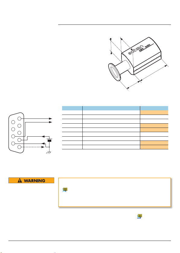
69.5
44.4
44.4
X
Connecting flange DN 16 ISO KF X = 30.8 mm
Connecting flange VCR®X = 27.7 mm
/41.9 mm (swivel nut)
The capacitance diaphragm gauge ASD2001, ASD2002,
ASD2003, ASD2004 has been designed for vacuum measurements
of gases in the pressure range of 1333 mbar to 10-4 mbar.
That’s It is an active gauge. It can be operated in connection with the
an Adixen controller (ACS 2000 or ACM2000) or as a stand alone
gauge sending a signal directly to other equipment.
Pin Signal ASD 200x 0/10 V
1Analog output 0-10 V (+) X
2 Not used
3 Not used
4 DC power input (+) X
5 Gauge ID X
6 Not used
7 Not used
8 Analog output 0-10 V (–) X
9 DC Power input (O V) (–) X
1
2
3
4
5
6
7
8
9
Analog out (+)
Gauge
identificate
resistance
Protective earth
+
–
Analog out (–)
24 V DC
ASD 200x - 0/10 V
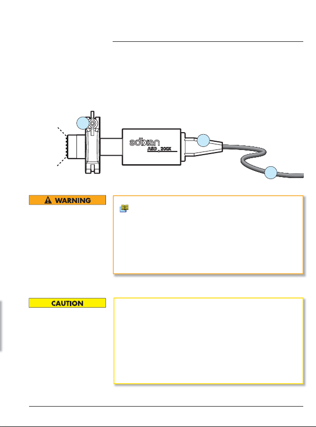
5- Gauge Installation
Connection
1
2
3
Safety . . . . . . . . . . . . . . . . . . . . . . . . . .p. 2
Responsibility and Warranty . . . . . . . . . .p. 3
Accessories . . . . . . . . . . . . . . . . . . . . . .p. 3
Technical Data . . . . . . . . . . . . . . . . . . . .p. 5 and 6
Gauge Installation . . . . . . . . . . . . . . . . .p. 7
Operation . . . . . . . . . . . . . . . . . . . . . . .p. 8 to 10
Gauge Removal . . . . . . . . . . . . . . . . . . .p. 11
Maintenance . . . . . . . . . . . . . . . . . . . . .p. 12
Returning the Products . . . . . . . . . . . . . .p. 13
Decontamination and Product Recycling. .p. 14
Declaration of Conformity. . . . . . . . . . . .p. 15
Contents
Symbols used
This type of warning is used to indicate a potential risk that can
cause serious injury or death if instructions are not followed.
This type of warning is used to indicate an imminent risk that can
cause serious injury or death if instructions are not followed.
This type of warning is used to indicate a potential risk that can
cause significant damage to the equipment and/or installations if
instructions are not followed.
1- Safety
General instructions
Use an Appropriate Power Source: Do not use this gauge with a
power supply over 30V DC. Disregarding this maximum voltage can
cause product damage or personnel injury.
Use appropriate grounds: An appropriate protective ground
connection is mandatory to avoid electric shock in the event of a
fault. Make sure there is no difference in protective ground potential
between gauge head and controller device/power supply.
Use Caution when installing this gauge.
Check that there are no harmful gasses or vapors within the lines
or chambers before opening them to install this gauge. Clean and
purge with a clean dry gas to remove these harmful gasses or
vapors if necessary.
Do not over pressure: Do not pressurize the inside of this gauge
beyond the receivable maximum pressure. Disregarding this can
lead to either damage to this gauge, or a gas leakage which may
cause personnel injury.
Maintenance of the product: Do not disassemble the gauge head
or electronics sub-assembly. Refer to section 8 for sub-assembly
replacement Instructions.
Do not modify the product: Do not modify the electrical or
mechanical components of this gauge. Any modification could cause
damage or personnel injury.
Skilled personnel: All work described in this document should be
carried out only by qualified persons who have suitable technical
training and the necessary experience.
Do not use this gauge with corrosive gases and take special
care with toxic gases, which can lead to gas leakage and cause
injury. In case of doubt contact Adixen application support for
recommendations.
The end-user assumes the responsibility in conjunction with the
process gases used.
- fails to observe the instructions in this document,
- uses this product in a way that is not consistent with the
manufacturer’s intended use,
- modifies this product in any way whatsoever,
- uses the product with accessories not listed in the product
documentation,
Gauge failures due to contamination, as well as expendable
parts (filament), are not covered by the warranty.
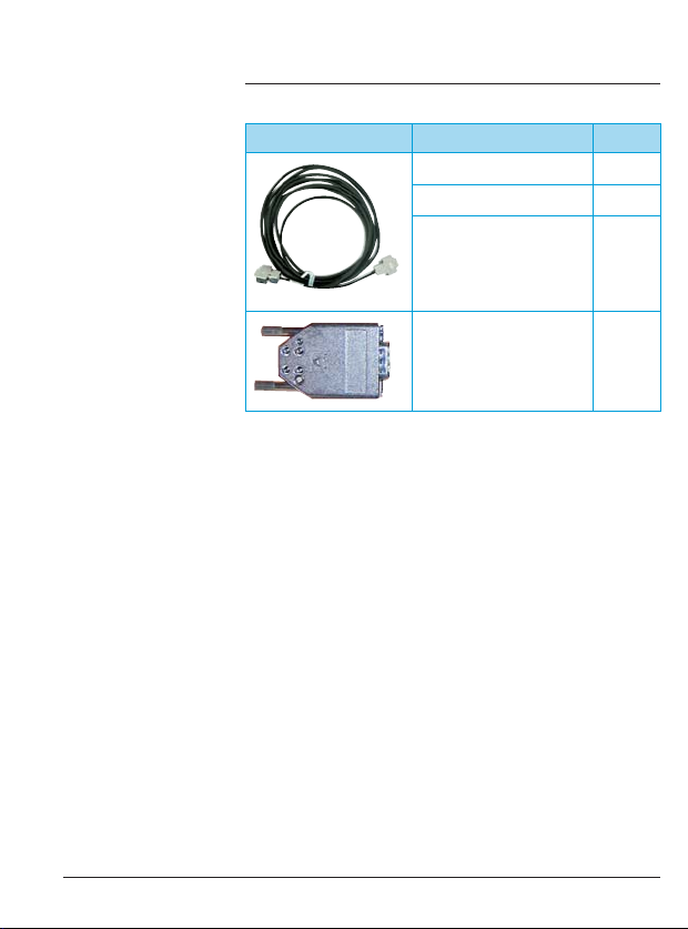
2- Responsibility and Warranty 3- Accessories
Description P/N
Gauge cable length (5 m) 112752
Gauge cable length (10 m) 112753
Gauge cable length (20 m) 112754
“D-Sub“ 9P (female)
connector (for custom
equipment connections)
114848
Specifications
4- Technical data
Gauges dimensions
4- Technical Data (ctd)
Electrical Connections
Do not use or apply voltage or ground to the pins marked “not used”.
Select the correct wire size for voltage if you use your own cable
( 4 p. 5) (1).
Always connect the protective ground wires or an electric shock can result.
Install a circuit breaker on the power source. Disregarding these
instructions can cause damage and/or injury.
(1) ”D-Sub” 9P (female) connector is available to allow the gauge
to be connected directly to customer equipment. ( 3 p. 4).
Connect the gauge to the installation using appropriate fitting
accessories (1) (from the Adixen product catalog).
Connect the cable (2). Use cable ties or other methods to support
the cable so that its weight does not put excessive strain on the
connector (3).
Do not touch the inside surfaces of this gauge with bare hands,
especially the inlet flange. Fingerprints will increase outgassing in
the gauge and cause erroneous pressure readings.
Install this gauge on the vacuum system with care. If it is
necessary to reposition it, do not twist or bend the sensor by the
electronic enclosure. Disconnect the gauge, position it in the correct
position, and connect it again.
Install this gauge away from vibration. High vibration can cause
the gauge to malfunction.
Install this gauge away from drastic temperature changes (away
from any heat sources or fans) for higher accuracy.
Do not exceed the max. overpressure rating of the gauge
( 4 p. 5). If the maximum pressure of the gauge is exceeded, it
can lead to gas leakage and cause injury.
Do not open the installation on which a gauge is installed when
the internal pressure is above 1 bar. Internal components may be
ejected and cause personal injury.
Do not use this gauge with corrosive, toxic, flammable or
explosive gasses.
Do not heat this gauge beyond 70 °C. Disregarding this instruction
can cause damage to the gauge circuits or a vacuum leak.
Intended Use: The capacitance diaphragm gauge ASD2001,
ASD2002, ASD2003, ASD2004 have been designed for vacuum
measurement of gases in the pressure range of
ASD2001 : 1x10⁻¹…1333 mbar, ASD2002 : 1x10⁻³…133.3
mbar, ASD2003 : 1x10⁻³…13.33 mbar, ASD2004 :
1x10- 4…1.333 mbar. The gauge must not be used for measuring
flammable or combustible gases which react in air.
English original version