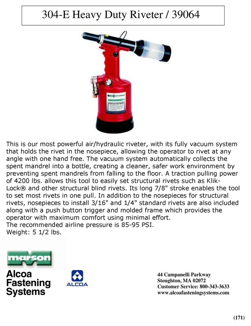
Alcoa 200 User manual

07-21-2009
HK154
INSTRUCTION MANUAL
MODEL 200
PNEUDRAULIC INSTALLATION TOOL

200 Series Tooling Alcoa Fastening Systems
2
EC Declaration of Conformity
Manufacturer:
Alcoa Fastening Systems, Industrial Products Group, 1 Corporate Drive, Kingston, NY,
12401, USA
Description of Machinery:
Model number 200 Pneudraulic Installation Tool
Relevant provisions complied with:
Council Directive related to Machinery (98/37/EC)
British Standard related to Hand-Held, Non-Electric Power Tools (EN 792-1:2000) - Safety
Requirements, Part 1, Assembly power tools for non-threaded mechanical
European Representative:
Rob Pattenden, Huck International, Ltd. Unit C Stafford Park 7, Telford Shropshire TF3 3BQ,
England, United Kingdom
Authorized Signature/date:
I, the undersigned, do hereby declare that the equipment specified above conforms to the
above Directive(s) and Standard(s).
Signature:
Full Name: Larry M. Krieg
Position: Engineering Manager
Installation Systems Division
Place: Kingston, New York, USA
Date: July, 2009
Test data to support the above information is on file at Alcoa Fastening Systems, Industrial Products Group, Kingston
Operations, Kingston, NY, USA.
Declared dual number noise emission values in accordance with ISO 4871
A weighted sound power level, LWA: 100.2 dB (reference 1 pW)
Uncertainty, KWA: 3 dB
A weighted emission sound pressure level at the work station, LpA: 89.2 dB (reference 20 µPa)
Uncertainty, KpA: 3 dB
C-weighted peak emission sound pressure level, LpC, peak: 106.5 dB (reference 20 µPa)
Uncertainty, KpC: 3 dB
Values determined according to noise test code ISO 15744, using as basic standards ISO 3744 and ISO 11203. The sum of
a measured noise emission value and its associated uncertainty represents an upper boundary of the range of values which
is likely to occur in measurements.
Declared vibration emission values in accordance with EN 12096
Measured Vibrations emission value, a:0.66 m/s2
Uncertainty, K: 0.075 m/s2
Values measured and determined according to ISO 8662-1, ISO 5349-2, and EN 1033

200 Series Tooling Alcoa Fastening Systems
3
C
CONTENTS
ONTENTS
EC DECLARATION OF CONFORMITY . . . . . . . . . . . . . . . . . . . . . . . . . . . .2
SAFETY . . . . . . . . . . . . . . . . . . . . . . . . . . . . . . . . . . . . . . . . . . . . . . . . . . .4
DESCRIPTION . . . . . . . . . . . . . . . . . . . . . . . . . . . . . . . . . . . . . . . . . . . . . . .5
SPECIFICATIONS . . . . . . . . . . . . . . . . . . . . . . . . . . . . . . . . . . . . . . . . . . . . .6
PRINCIPLE OF OPERATION . . . . . . . . . . . . . . . . . . . . . . . . . . . . . . . . . . . . .7
PREPARATION AND USE . . . . . . . . . . . . . . . . . . . . . . . . . . . . . . . . . . . . . .8
FILLING AND BLEEDING . . . . . . . . . . . . . . . . . . . . . . . . . . . . . . . . . . . .9-10
SETTING AND CHECKING SHIFT VALVE . . . . . . . . . . . . . . . . . . . . . .11-13
SPINDLE LOADS & HYDRAULIC PRESSURES AT SHIFT . . . . . . . . . . . .14
MAINTENANCE . . . . . . . . . . . . . . . . . . . . . . . . . . . . . . . . . . . . . . . . . . . . .15
TROUBLESHOOTING . . . . . . . . . . . . . . . . . . . . . . . . . . . . . . . . . . . . . . . . .16
AIR AND/OR HYDRAULIC FLUID LEAKAGE . . . . . . . . . . . . . . . . . . . .17-21
MAJOR COMPONENTS ASSEMBLY AND DISASSEMBLY . . . . . . . . . .22-37
KITS AND ACCESSORIES . . . . . . . . . . . . . . . . . . . . . . . . . . . . . . . . . .38-43
TOOL & PRODUCT UPDATE PB141 . . . . . . . . . . . . . . . . . . . . . . . . . . .44
NOTE
Throughout this manual, reference numbers for
finding a component or (sub) assembly are linked
to the figure number where they will be found.
Example: (2-21) indicates Pull Piston and Quad
Ring Assembly, part number 111078 found in
Figure 2.

200 Series Tooling Alcoa Fastening Systems
4
S
SAFETY
AFETY
This instruction manual must be read,
with particular attention to the following
safety guidelines, by any person servic-
ing or operating this tool.
1. Glossary
Notes - are reminders of required procedures.
Bold, Italic type and underlining - empha-
sizes a specific instruction.
2. A half hour long hands-on training session with qualified personnel
is recommended before using Huck equipment.
3. Huck equipment must be maintained in a safe working condition at
all times. Tools and hoses should be inspected on a regular basis
for damage or wear. Any repair should be done by a qualified
repairman trained on Huck procedures.
4. Repairman and Operator must read manual prior to using equip-
ment. Warning and Caution stickers/labels supplied with equipment
must be understood before connecting equipment to any primary
power supply. As applicable, each of the sections in this manual
have specific safety and other information.
5. Read MSDS Specifications before servicing the tool. MSDS
Specifications are available from the product manufacturer or your
Huck representative.
6. When repairing or operating Huck installation equipment, always
wear approved eye protection. Where applicable, refer to ANSI
Z87.1 - 2003
7. Disconnect primary power source before doing maintenance on
Huck equipment or changing Nose Assembly.
8. Tools and hoses should be inspected for leaks at the beginning of
each shift/day. If any equipment shows signs of damage, wear, or
leakage, do not connect it to the primary power supply.
9. Mounting hardware should be checked at the beginning of each
shift/day.
10. Make sure proper power source is used at all times.
11. Release tool trigger if power supply is interrupted.
12. Tools are not to be used in an explosive environment unless specif-
ically designed to do so.
13. Never remove any safety guards or pintail deflectors.
14. Ensure deflector or pintail collector is installed and operating prior
to use.
15. Never install a fastener in free air. Personal injury from fastener
ejecting may occur.
16. Always clear spent pintail out of nose assembly before installing the
next fastener.
17. There is possibility of forcible ejection of pintails or spent mandrels
from front of tool.
18. If there is a pinch point between trigger and work piece, use remote
trigger. (Remote triggers are available for all tooling).
19. Unsuitable postures may not allow counteracting of normal expect-
ed movement of tool.
20. Do not abuse tool by dropping or using it as a hammer. Never use
hydraulic or air lines as a handle or to bend or pry the tool.
Reasonable care of installation tools by operators is an important
factor in maintaining tool efficiency, eliminating downtime, and in
preventing an accident which may cause severe personal injury.
21. Never place hands between nose assembly and work piece. Keep
hands clear from front of tool.
22. There is a risk of crushing if tool is cycled without Nose Assembly
installed.
23. Tools with ejector rods should never be cycled with out nose
assembly installed.
24. When two piece lock bolts are being used always make sure the
collar orientation is correct. See fastener data sheet of correct posi-
tioning.
25. Tool is only to be used as stated in this manual. Any other use is
prohibited.
26. There is a risk of whipping compressed air hose if tool is pneu-
draulic or pneumatic.
27. Release the trigger in case of failure of air supply or hydraulic sup-
ply.
28. Use only fluids or lubricants recommended.
29. Disposal instruction: Disassemble and recycle steel, aluminum and
plastic parts, and drain and dispose of hydraulic fluid in accordance
with local lawful and safe practices.
Product complies with requirements
set forth by the relevant European
directives.
Read manual prior to using
equipment.
Eye protection required while
using this equipment.
Hearing protection required while
using this equipment.
WARNINGS - Must be understood to
avoid severe personal injury.
CAUTIONS - show conditions that will
damage equipment and or structure.

200 Series Tooling Alcoa Fastening Systems
5
Description Page
General......................................................................................................................................1
Specifications ............................................................................................................................1
Outline Drawing ........................................................................................................................2
Principle of Operation................................................................................................................3
Operation Sequence as Double Action Tool ......................................................................3
Operation Sequence as Single Action Tool ........................................................................3
Preparation and Use
Preparation ................................................................................................................................4
Use ............................................................................................................................................5
Filling and Bleeding ..................................................................................................................5
Manually..............................................................................................................................5
Fill and Bleed Unit 970-100 ................................................................................................6
Setting and Checking Shift Valve ..............................................................................................9
Shift Setting Kit 107569 ............................................................................................................9
Shift Setting Kit 101300 ..........................................................................................................11
Spindle Loads & Hydraulic Pressures at Shift ........................................................................12
Maintenance
Good Service Practices ..........................................................................................................13
Preventive Maintenance..........................................................................................................13
Troubleshooting ......................................................................................................................14
Tool Malfunction ......................................................................................................................14
Air Leakage ............................................................................................................................15
Hydraulic Fluid Leakage..........................................................................................................19
D
DESCRIPTION
ESCRIPTION

200 Series Tooling Alcoa Fastening Systems
6
Length (overall) ....................................71/2 inches ...........................................................190 mm
Height (overall) ..................................13-7/8 inches.......................................................... 352 mm
Width (head) ..............................................2 inches ............................................................51 mm
Width (cylinder)....................................4.3/4 inches ..........................................................121 mm
Weight 10-1/2 pounds....................................4.8kg
Stroke ..............................................1-3/16 inches ............................................................30 mm
Air Required ............................................18CFM@ ........................................................009 m3/s
......90-100 psi ..................................................620-689 kPa
Hydraulic Fluid: 4.8kg ATF meeting DEXRON III, DEXRON IV, MERCON, Allison C-4 or equiva-
lent specifications.
S
SPECIFICATIONS
PECIFICATIONS

200 Series Tooling Alcoa Fastening Systems
7
P
PRINCIPLE
RINCIPLE
OF
OF O
OPERATION
PERATION
Operation as A Double Action Tool
When the tool is connected to an air supply and
the trigger (3-31) is depressed, air pressure acts on the air piston (3-44) and moves it for-
ward. This causes the small hydraulic piston (3-40) to act on a volume of hydraulic fluid in the
handle assembly (1-4). Pressurized fluid is forced into the head assembly (1-1) to move the
pull piston (2-21) in conjunction with the nose assembly to start the fastener installation.
Pressurized fluid is also acting on the shift piston (2-12) and shift valve (4-19), whose shift
force is controlled by the shift spring (4-29) and adjustment of the shift valve adjusting screw
(4-30). As the fluid pressure increases, the shift valve opens and allows the fluid resisting
movement of the shift piston (2-12) to exhaust. The shift piston moves forward and acts on
the thrust bushing and inner anvil of the nose assembly to drive the lock of the fastener.
Continued travel of the air piston increases the hydraulic pressure, causing the pull piston to
continue its travel. This causes the pintail of fastener to break off and the installation is com-
plete. ‘the trigger is released and all components return to their original position and the cycle
is complete.
Operation As A Single Action Tool
The tool operates the same for installing other
blind rivets and HUCKBOLT® Fasteners except
that the shift valve mechanism does not have a
function.
CAUTION
REASONABLE CARE OF INSTALLATION TOOLS BY OPERATORS IS AN IMPORTANT FACTOR IN MAIN-
TAINING TOOL EFFICIENCY AND IN REDUCING DOWN-TIME.
DO NOT ABUSE THE TOOL BY DROPPING IT, USING IT AS A HAMMER OR OTHERWISE CAUSING
UNNECESSARY WEAR AND TEAR.
BE SURE THERE IS ADEQUATE CLEARANCE FOR THE TOOL AND OPERATOR’S HANDS BEFORE PRO-
CEEDING.
THE PINTAIL DEFLECTOR MUST ALWAYS BE IN PLACE BEFORE USING THE TOOL.

200 Series Tooling Alcoa Fastening Systems
8
(See Good Services Practices.)
The Model 200 Huck Installation Tool is shipped with
a plastic plug in the swivel air inlet connector (3-4).
This connector has 1/4-18 female pipe threads to
accept the hose fittings. Quick disconnect fittings and
3/8 inside diameter air hose are recommended. (Air
hose and quick disconnect fittings are not available
from Huck.)
An air filter-regulator-lubricator is also recommended.
An air supply of 90-100 psi capable of 18 CFM must
be available. (Based on 30 tool cycles per minute).
The air connector bolt (3-5) has an air relief valve
built in to exhaust air at 100-110 psi.
1. Remove plastic plug from air inlet connector and
pour in a small quantity of Automatic Transmission
Fluid. Assemble the hose fittings to be used.
2. Set air pressure to 90-100 psi.
3. Blow out air hose and connect to the tool.
4. Hold tool upside down and cycle tool 8 or 10
times by depressing and releasing the trigger.
5. Set tool upright and remove filler plug (3-13) and
check hydraulic fluid level. Add fluid if necessary.
6. If tool is to be used in a single action application,
the shift valve adjusting screw (4-30) should be
backed out leaving surface of adjusting screw 1/8”
below surface of cylinder.
7. If tool is to be used in a double action application
to install one of the following fasteners, the shift
valve must be set.
AF540911-460 & 461/CKL-X
NA51919 & 1921/MLS
MS21140 & 21141/Huck Blind Bolt
M590353 & 90354/Huck Blind Bolt
Oversize Huck Blind Bolt
Select the shift valve setting from Table 16 for the
fastener to be installed and the method of setting and
checking to be used: (1) Spindle Load at shift using
Kit 107569 (preferred method) (2) Hydraulic Pressure
at shift using Kit 101300.
8. Select nose assembly for the fasteners to be
installed. See SELECTION CHARTS, Form 461,
in HUCK INSTALLATION EQUIPMENT DATA or
available separately from your Huck representa-
tive.
9. Install nose assembly to the tool following the
instructions on the NOSE ASSEMBLY DATA
SHEET furnished with each nose assembly.
10.Install a few fasteners in a test plate of the proper
thickness and having the proper size holes.
Observe the action of the tool and nose assembly;
the bulbing of the fastener sleeve and driving of
the lock for a double action fastener or swaging of
the collar for a single action fastener.
NOTE: If the tool has been disassembled for
repair, the hydraulic system must be replenished
before pre-paring it for use. See Filling and
Bleeding for instructions.
DOUBLE ACTION APPLICATION AND/OR BLIND
RIVET APPLICATION
The fastener may be placed in the work hole or in the
end of the nose assembly. In either case, the tool
and nose assembly must be held against the work
and at right angles to it. Depress trigger and hold it
depressed until a sound denoting the pintail breaking
is heard.
SINGLE ACTION APPLICATION
Place pin in work hole and collar over the pin. (If col-
lar has only one end tapered, that end should be out
towards the tool). Hold the pin and push nose
assembly onto pin protruding through the collar until
nose assembly anvil touches the collar. Depress trig-
ger and hold it depressed until collar is swaged and a
sound denoting the pintail breaking is heard.
P
PREPARATION
REPARATION
AND
AND U
USE
SE
WARNING
Never push the Nose Assembly onto the
pin of a HUCKBOLT© fastener without the
collar in place. Injury to workers and dam-
age to the Nose Assembly could result
when the pintail breaks because thepin
will eject forcibly from the other side of
the work.

200 Series Tooling Alcoa Fastening Systems
9
F
FILLING
ILLING
AND
AND B
BLEEDING
LEEDING
The Model 200 Tool does not require filling and bleed-
ing often. When it is necessary, due to loss of fluid
because of a damaged seal, or when the tool has
been overhauled, there are two methods which may
be used:
(1) - MANUALLY
1. Remove air hose from tool.
2. Turn in balancing valve bleed screw (2-40) all the way.
3. Remove filler plug (3-13) and fill with Automatic
Transmission Fluid AQ-ATF-1428A or equivalent until the
fluid level is up to the bottom of the filler hole threads. (A
filler bottle and fluid is available from Huck as part num-
ber 100932. It is included in SERVICE TOOL KIT 42-
233).
4. Wipe filler plug with a clean, lint-free cloth and replace
and tighten.
5. Attach air hose to tool, turn it upside down, and cycle 12
times by depressing and releasing the trigger.
6. Set tool upright and remove air hose.
7. Back-out balancing valve bleed screw (2-40) all the way.
Leave this screw backed-out.
8. Remove filler plug and again add fluid until the level
reaches the bottom of the filler hole threads.
9. Replace filler plug and tighten.
10. Attach air hose to tool and turn it upside down again and
cycle tool 50 times permitting full stroke for each cycle.
11. Set tool upright again and repeat steps 8, 9 and 10 until
fluid level remains at the bottom of the filler hole threads,
the foam and bubbles have disappeared and the fluid is
clear.
(2) - USING FILL AND BLEED UNIT 970-100
(Preferred method)
1. Fill unit with hydraulic fluid, Automatic Transmission
Fluid, AQ-ATF-1428A or equivalent.
2. Plug unit into 110 volt, single phase, 50/60 hertz outlet.
3. Remove filler plug (3-13). Screw in adapter (8-1) of Pull
Pressure Tube Assembly.
4. Remove ball check screw (2-49) from valve B (13-10).
Use magnet in filler plug to remove spring (2-52) and
ball (2-51). Screw in adapter (8-2) of RETURN pressure
Tube Assembly.
5. Turn bleed screw (2-40) all the way out. (Balance valve
(2-33) will be closed. Figure 13-11)
6. Turn unit switch ON. Adjust relief valve to 50-60 psi.
Hold tool in all positions until air bubbles stop flowing in
RETURN tube. Hold tool in upright position for the final
portion of the bleeding. Back out relief valve retainer (2-
44) a few turns until clear fluid (free of air) flows out.
Use a combination of “RUN” and “JOG”. Total time for
this step is approx. three minutes. Turn unit switch OFF.
7. Unscrew adapter (8-1) from filler port and replace filler
plug (3-13).
8. Remove Tube Assembly from PULL pressure port of unit
and install other Tube Assembly, P/N 110777.
9. Remove bleed plug (4-2) from front of cylinder. Screw in
adapter (8-2) of PULL pressure Tube Assembly.
10. Turn bleed screw (2-40) all the way in. (Balance valve
(2-33) will be open. Figure 13-11).
11. Turn unit switch to “ON’’. When air bubbles stop flowing
in RETURN tube, back out bleed screw (2-40). The bal-
ance valve (2-33) will be closed and the pull piston (2-
21) will move back full stroke. When flow stops out valve
B, screw in bleed screw (2-40) to open balance valve (2-
33) and re-establish flow. Hold tool head down to flush
all air out of valve B. Use a combination of “RUN’’ and
“JOG’’. Total time for this step is approx. five minutes.
Turn unit switch OFF.
12. Remove Tube Assembly from bleed port in cylinder and
re-assemble bleed plug (4-2).
13. Remove ball check screw (2-53) and guide (2-31) from
valve A. Figure 13-9 Leave spring (2-52) and ball (2-51)
in place. Screw in adapter of Tube Assembly installed in
PULL pressure port of unit.
14. Turn unit switch ON. Back out shift valve adjusting screw
(4-30), in bottom of cylinder, until there is flow out valve
B. Hold tool in all positions, especially head down, until
air bubbles stop flowing in the RETURN tube. Total time
for this step is ten minutes minimum. Turn unit switch
OFF.
15. Remove tube assemblies from the tool. Reassemble
components in ports of valves A & B. Fill ports to bottom
of threads with hydraulic fluid. Assemble ball check
screw (2-53) in valve A port and ball check screw (2-49)
in valve B port.
16. If pull piston (2-21) is in back position, turn in bleed
screw (2-40), remove filler plug (3-13), and manually
return the pull piston to the forward position.
17. Assemble filler plug (3-13) and back out bleed screw (2-
40). Turn in shift valve adjusting screw (4-30) a few
turns. Tool is now ready to set and check the shift valve
adjustment.
200 Series Tooling Alcoa Fastening Systems
10
Fig. 8
Fill & Bleed Unit 970-100

200 Series Tooling Alcoa Fastening Systems
11
S
SETTING
ETTING
AND
AND C
CHECKING
HECKING S
SHIFT
HIFT V
VALVE
ALVE
U
USING
SING S
SHIFT
HIFT S
SETTING
ETTING K
KIT
IT
P
PREFERRED
REFERRED M
METHOD
ETHOD - KIT 107569 (F
- KIT 107569 (FIG
IG 9)
9)
1. Use only a tool which has been prepared for use and
filled and bled per instructions in this manual.
2. A filtered-regulated-lubricated air supply capable of sup-
plying 18 CFM @ 90-100 psi must be available.
3. Screw Retaining Nut I 00530 (5-1) againist head (2-1).
4. Assemble Adapter 107564 through Skidmore-Wilhelm
Tester 107573 and engage threads of tool pull piston (2-
21). Tighten “finger tight.”
5. Screw Air Metering Fitting 101303 into air connector and
air supply hose. Set regulator for 90-I 00 psi.
6. Back out shift valve adjusting screw (4-30), keeping sur-
face of adjusting screw approximately 1/8” below sur-
face of cylinder. Use Wrench 100878.
7. Depress tool trigger (3-3 1) quickly and watch needle on
tester gage. Full spindle load will be shown. There will
not be a pause indicating shifting of the shift valve
because it is inoperative with adjusting screw backed
out. Release trigger. Do not hold down.
8. Select spindle load at shift from table 15 for Huck
Fastener to be installed.
9. Turin in adjusting screw until needle of gage pauses
before reaching full spindle load when trigger is
depressed. This is ‘‘Spindle Load at Shift.’’
10. Adjust screw to obtain desired “Spindle Load at Shift”
selected from table.
11. Trigger tool ten times to verify setting Note: The needle
will bounce slightly when shift occurs. Do not confuse
this bounce with the pause indicating shift.
12. Disconnect air supply and remove setting kit and
101303 Air Metering Fitting from tool.
13. Attach nose assembly per instructions on Nose
Assembly Data Sheet.
14. Install a few fasteners in a test plate of proper thickness
and with proper size holes to verify that shift valve has
been set properly and that nose assembly is functioning
properly.
A
ALTERNATE
LTERNATE M
METHOD
ETHOD - KIT101300 (F
- KIT101300 (FIG
IG 10)
10)
1. Use only a tool which has been prepared for use and
filled and bled per instructions in this manual.
2. A filtered-regulated-lubricated air supply capable of sup-
plying 18 CFM@ 90-100 psi must be available.
3. Screw Stop Nut 101304 onto threads of pull piston (2-
21). Tighten “finger tight.”
4. Remove bleed plug (4-2) from side of cylinder (4-1) and
screw in Adapter 101302 with Gage 101301. Note: Be
sure there is an O-ring on the Adapter.
5. Screw Air Metering Fitting 101303 into air connector (3-
4).
6. Attach air supply hose to tool. Set regulator for 90-100
psi.
7. Back out shift valve adjusting screw (4-30) flush with
bottom of cylinder (4-1). Use Wrench 100878.
8. Depress tool trigger (3-31) quickly and watch needle on
Gage 101301. Full spindle load will be shown. There will
not be a pause indicating shifting of time shift valve
because it is inoperative with adjusting screw backed
out. Release trigger — do not hold down.
9. Select hydraulic pressure at shift from table 15 for Huck
Fastener to be installed.
10. Turn in adjusting screw until needle of gage pauses
before reaching full spindle load when trigger is
depressed. This is “Hydraulic Pressure at Shift.”
11. Adjust screw to obtain desired hydraulic pressure at shift
selected from the table.
12. Trigger tool ten times to verify setting. Note: The needle
will bounce slightly when shift occurs. Do not confuse
this bounce with the pause indicating shift.
13. Disconnect air supply and remove setting kit including
Air Metering Fitting 101303.
14. Attach nose assembly per instructions on Nose
Assembly Data Sheet.
15. Install a few fasteners in a test plate of proper thickness
and with proper size holes to verify that shift valve has
been set properly and that nose assembly is functioning
properly.

200 Series Tooling Alcoa Fastening Systems
12
Fig. 9
Using Shift Setting Kit 107569

200 Series Tooling Alcoa Fastening Systems
13
Fig. 10
Using Shift Setting Kit 101300

200 Series Tooling Alcoa Fastening Systems
14
When used to install double action fasteners, the shift valve of the Model 200 H.I.T. must be adjusted to insure
the proper installation of various fasteners. Two methods of checking the shift valve setting are available:
Method #1: Shift Setting Kit No. 107569 employs a Skidmore-Wilhelm Tension Tester to check the spindle
Load at shift, in pounds.
Method #2: Shift Setting Kit No. 101300 employs a hydraulic pressure gauge to check the hydraulic pressure
at shift, in pounds per square inch (psi).
The table below shows the ‘Spindle load at Shift” and “Hydraulic Pressure at Shift” for various fasteners.
S
SPINDLE
PINDLE L
LOADS
OADS
AND
AND H
HYDRAULIC
YDRAULIC
P
PRESSURES
RESSURES
AT
AT S
SHIFT
HIFT
Table 15

200 Series Tooling Alcoa Fastening Systems
15
M
MAINTENANCE
AINTENANCE
GOOD SERVICE PRACTICES
The efficiency and life of any tool depends upon
proper maintenance and good service practices.
The tool should be serviced by personnel who are
thoroughly familiar with it and how it operates. If possi-
ble, the tool should be serviced by personneI trained
specifically in servicing the Model 200 Huck
Installation Tool. (See notice inside back cover of this
manual.) A clean, well-lighted area should be avail-
able. Special care must be taken to prevent contami-
nation of the hydraulic system. Proper hand tools, both
standard and special, must be available (See Service
Tool Kit). All parts must be handled carefully and
examined for damage or wear. Seals (O-rings and
quad rings) and back-up rings should be inspected
and replaced if nicks or wear is detected. A good prac-
tice to follow is to always replace O-rings, quad rings
and back-up rings when the tool is disassembled for
any reason. Service Parts Kit 42-236 includes perish-
able parts and should be available at all times. Other
components, as experience dictates, should also be
available. LUBRIPLATE 130AA™(Fiske Brothers
Refining Co.) should be used to facilitate assembly of
seals, components and assemblies. Components and
assemblies should be disassembled and assembled in
straight line without bending, cocking or undue force.
Disassembly and assembly procedures outlined in this
manual should be followed.
PREVENTIVE MAINTENANCE
The 200 Huck Installation Tool is a production tool,
requiring a minimum amount of maintenance.
Adherence to the Preventive Maintenance Chart
below, however, will help insure longer life with maxi-
mum operating efficiency, and eliminate unnecessary
breakdowns. Also, refer to Troubleshooting.

200 Series Tooling Alcoa Fastening Systems
16
T
TROUBLESHOOTING
ROUBLESHOOTING
TOOL MALFUNCTION CAUSE AND
REMEDY
REMEDY
A. Air supply pressure low. Air pressure of 90-100 psi
required.
B. Air in hydraulic system. Refill and bleed tool per
instructions.
C. Check nose assembly for completeness and prop-
er installation per instructions.
D. Shift valve adjustment set too high (13-7). Readjust
counter-clockwise per instructions.
E. Shift valve adjustment set too low (13-7). Re adjust
clockwise per instructions.
F. Relief valve (13-8) not sealing. Check 3/16 inch
ball (2-47) and seat (2-3) for foreign particles.
Clean if dirty. Reseat ball by tapping against brass
seat. Replace ball or seat if damaged.
G. Check valve (13-9) for leakage. Clean and reseat
ball (2-51) by tapping. If ball or seat (2-2A) are
damaged, replace.
H. Bleed screw (2-40) not backed out to stop (13-11).
Balance valve (2-33) stuck in open position or for-
eign material between valve and seat. Free valve
and remove any foreign particles. If valve or seat
(2-4) are damaged, replace.
I. Check valve (13-10) for leakage. Clean valve and
reseat ball (2-51) by tapping. If ball or seal (2-2B)
are damaged, replace.
J. Shift sleeve (4-27) loose (13-12). Tighten with
Wrench 100878.
K. Shift valve seat (4-13) not sealing (13-13). Replace
seat if foreign particles are imbedded in seal, or if
seat is damaged.
L. Shift plunger (4-10) sticky in sleeve (4-7). Remove
plunger from sleeve. If plunger or sleeve bore is
scored, replace (13-13).
M. Extreme temperature variation. Adjust shift valve
(13-7) as necessary.
CAUTION: Make certain that Valve compo-
nents are not magnetized.

200 Series Tooling Alcoa Fastening Systems
17
A
AIR
IR L
LEAKAGE
EAKAGE C
CAUSE
AUSE
AND
AND R
REMEDY
EMEDY
A. Trigger linkage not properly adjusted. With air on
tool and trigger in idle position, it should have
some free motion before actuating air valves. With
trigger in depressed position, trigger (3-31), lever
(3-29) and cross bar (3-28) should not bottom on
handle casting or hand grip (3-32). If either of
these conditions occurs, replace worn, bent, or
broken parts.
B. Brass air valve seat (3-24) leaking. Lap or reseal
with an 11/32 inch ball. Replace seat if leakage still
occurs.
C. Right rear insert (3-2) leaking. Replace spring (3-
19), if broken. Reseat insert with ball (3-18) by tap-
ping against insert. Replace if leakage still occurs.
D. Left insert (3-2) leaking. Reseat ball against insert.
Replace insert if leakage still occurs.
E. Right front insert (3-2) leaking. (See D above.)
F. Slight leakage at this point is permissible.
G. If leakage is excessive, check intensifier gland O-
ring (3-47). (First remove handle assembly from
cylinder assembly.) It is recommended that H and I
also be performed at this time.
H. Remove intensifier gland (3-35) and check O-rings.
Replace if damaged.
I. Remove intensifier gland from piston rod (3- 34).
(First remove small hydraulic piston (3-40) by
removing screw (3-43) and slipping piston from
rod.)
J. If leakage occurs at small hole in acorn nut (3-12)
on swivel fitting, reduce air supply. (90-100 psi air
pressure recommended.) If leak stops but air pres-
sure is then too low, add shims (3-9) as required to
obtain seal at proper pressure. If leakage still
occurs, replace valve (3-8).
K. If leakage occurs at a point other than the hole in
the acorn nut, disassemble nut and swivel bolt
from assembly. Replace O-ring (3-11), quad rings
(3-6) and flat gasket (3-7) as required.
L. Socket head screws loose. Tighten.
M. O-ring seals between faces leaking. Replace.
N. Insufficient bIeeding can appear as a leak into the
hydraulic system. Rebleed.
O. Head assembly to handle assembly and/or handle
assembly to cylinder assembly screws loosened.
Tighten screws.
P. Improper hydraulic fluid. Poor substitutes can dam-
age O-rings and seals, and cause foaming. See
instructions for proper fluid and procedure.
Q. Rubber reservoir diaphragm (4-4) leaking. Replace
as required.
R. Sheared or worn O-rings or seals in oil-to-air joints.
Replace as required .
S. Leakage in weldment or handle subassembly (3-1)
or at plugs in Cylinder Subassembly 100875.
CAUTION: Exercise care to prevent scor-
ing Rod. Slip off Gland and replace lower
internal QUAD Ring.

200 Series Tooling Alcoa Fastening Systems
18
SERVICE NOTES

200 Series Tooling Alcoa Fastening Systems
19
Fig. 13
Sectional View

200 Series Tooling Alcoa Fastening Systems
20
Fig. 12
Miscellaneous Valves
Table of contents
Other Alcoa Tools manuals

Alcoa
Alcoa 2503 series User manual

Alcoa
Alcoa Huck 2024 Series User manual

Alcoa
Alcoa Huck 2480RI User manual

Alcoa
Alcoa 2624 User manual

Alcoa
Alcoa 304-E User manual

Alcoa
Alcoa Huck 256 Series User manual

Alcoa
Alcoa 7142 User manual

Alcoa
Alcoa HK-150 Series User manual

Alcoa
Alcoa Huck HK150-S456 User manual
Popular Tools manuals by other brands

Rauckman Utility Products
Rauckman Utility Products METERPULLER M-001 Owner's/operator's manual

Legacy
Legacy Flexzilla L8011FZ Owner's instructions

tekton
tekton 24340 Operator's manual

BEA
BEA 554 DCC Spare parts list/service instructions

Facom
Facom 14.9X12 instruction manual

NovoPress
NovoPress AFP101 operating manual