BIAX KGS 27 User manual

MA-NR.: 001580592
Stand 08.09.2016
Originalmontageanleitung
Translation of the original assembly instructions
Handstücke für biegsame
Wellen Antriebe
Handpieces for flexible shafts
power units
Gerade Ausführung
Straight execution
KGS 27
KGS 10-9
Abgewinkelte Ausführung
Angled execution
W 6-9
W 627
W 627-45
Diese Anleitung muss dem Anwender (Werker) ausgehändigt werden!
This manual must be handed to the user (operator)!
Schmid und Wezel GmbH
Maschinenfabrik
Maybachstraße 2
D -75433 Maulbronn
Telefon: 07043 / 102-0
Telefax: 07043 / 102-78
E-Mail: biax-v[email protected]
Webadresse: www.biax.de

Originalmontageanleitung
- 2 -
Technische Daten
Bezeichnung
Ausführung
Zulässige
Höchstdrehzahl
Max. Werkzeugaufnahme
Spannzangentyp /
Werkzeug-Spannsystem
Anschluss
Wellenseite
Gewicht
min-1
mm
mm
kg
KGS 27
Gerade
34.000
6
ZG 4
Vierkant 5,0
0,22
KGS 10-9
Gerade
9.000
10
ZG1A
Vierkant 8,6
0,55
W 6-9
Winkel 90°
9.000
6
ZG 4
Vierkant 8,6
0,57
W 627
Winkel 90°
15.000
6
ZG 4
Vierkant 5,0
0,38
W 627-45
Winkel 45°
15.000
6
ZG 4
Vierkant 5,0
0,38

Originalmontageanleitung
- 3 -
Allgemeine Hinweise
Diese Montageanleitung ist Bestandteil des
Lieferumfangs. Sie ist in Zugriffsnähe bereit-
zuhalten und bleibt auch bei Weiterverkauf der
unvollständigen Maschine beim Gerät.
Änderungen durch technische
Weiterentwicklungen gegenüber den in dieser
Montageanweisung dargestellten Ausführungen
behalten wir uns vor.
Nachdrucke, Übersetzungen und
Vervielfältigungen in jeglicher Form, auch
Auszugsweise, bedürfen der schriftlichen
Zustimmung des Herausgebers.
Verantwortlichkeit des Betreibers
Der Betreiber hat die geltenden nationalen
Unfallverhütungsvorschriften und technischen
Regeln einzuhalten.
Der Betreiber darf die unvollständige Maschine nur
von geschultem und zuverlässigem Personal in
Betrieb nehmen lassen.
Der Betreiber hat dafür Sorge zu tragen, dass die
Bediener die Montageanleitung gelesen und
verstanden haben, bevor sie die unvollständige
Maschine in Betrieb nehmen.
Der Betreiber hat dafür zu sorgen, dass kein
Unbefugter an die unvollständige Maschine
gelangen kann.
Die innerbetrieblichen Arbeitsschutzvorschriften
sind zu beachten.
Bestimmungsgemäße Verwendung
Das BIAX-Handstück für die Anbindung an die
BIAX-biegsame Wellen wird zur Aufnahme von
Schleifstiften zum handgeführten:
Schleifen
Fräsen
Entgraten
Polieren und
Bürsten
von unterschiedlichen Materialien eingesetzt.
Der Antrieb geschieht durch die BIAX Antriebs-
maschine mit biegsamer Welle.
Es ist darauf zu achten, dass ausschließlich
BIAX Produkte und Schleifstifte an den
Handstücken angeschlossen werden.
Jeglicher Gebrauch der BIAX-Handstücke für
biegsame Wellen außerhalb der genannten
Einsatzgebiete, sowie bauliche Veränderung
der Handstücke ist ohne Zustimmung durch
Schmid & Wezel nicht zulässig. Bei
Zuwiderhandlung entfällt jegliche Haftung für
Folgeschäden.
Sicherheit
Sicherheitskennzeichnung
Folgende Signalwörter werden in Verbindung mit
Sicherheitszeichen zur Darstellung möglicher
Gefahren in diesem Dokument verwendet:
Gefahr!
Tod, schwere Körperverletzung
oder erheblicher Sachschaden
werden eintreten wenn die
entsprechenden Vorsichtsmaß-
nahmen nicht getroffen werden!
Warnung!
Tod, schwere Körperverletzung
oder erheblicher Sachschaden
können eintreten, wenn die
entsprechenden Vorsichtsmaß-
nahmen nicht getroffen werden!
Vorsicht!
Leichte Körperverletzung kann
eintreten, wenn die entsprech-
enden Vorsichtsmaßnahmen
nicht getroffen werden!
Achtung!
Sachschaden kann eintreten,
wenn die entsprechenden
Vorsichtsmaßnahmen nicht
getroffen werden!
Sicherheitshinweise
Warnung!
Bei Nichtbeachtung der
Sicherheitshinweise besteht
akute Verletzungsgefahr!
Beim Schleifen können Funken
oder Späne die Augen verletzen.
Tragen Sie bei der Arbeit immer
eine Schutzbrille!
Je nach Art der Bearbeitung
kann der angegebene
Geräuschpegel überschritten
werden.
Verwenden Sie einen Gehör-
schutz!
Arbeiten Sie bei Staub-
entwicklung nur mit Atemschutz
und schalten Sie die Staub-
absaugung an Ihrem
Arbeitsplatz ein!

Originalmontageanleitung
- 4 -
Gesundheit
Vorsicht!
Vibration kann auf den ganzen
Körper, speziell auf Arme und
Hände, übertragen werden. Sehr
starke, sowie andauernde
Vibration kann Nerven- und
Gefäßstörungen verursachen!
Gefahr!
Lebensgefahr durch Berühren
spannungsführender Teile.
Keine Arbeiten an spannungs-
führenden Teilen ausführen.
Umgang mit dem BIAX Handstück
Die Montageanleitung richtet
sich an eingewiesenes
Fachpersonal!
Einzugsgefahr!
Während der Arbeit nur
enganliegende Kleidung tragen.
Nehmen Sie Schmuck vor
Arbeitsbeginn ab. Verwenden
Sie bei langen Haaren unbedingt
ein Haarnetz!
Verletzungsgefahr!
Das eingeschaltete Werkzeug ist
vom Körper weg zu halten!
Nicht in laufendes Werkzeug
greifen!
Werkzeug vorsichtig
handhaben!
Explosionsgefahr!
Beim Schleifen können Stäube
entstehen, die eine explosions-
fähige Atmosphäre bilden kön-
nen. Beachten Sie die in Ihrem
Land gültigen Vorschriften für
die zu bearbeitenden
Materialien!
Das Handstück darf nur in einwandfreiem,
funktionstüchtigem Zustand betrieben werden.
Die vorgeschriebenen Drehzahlen und die Mindest-
Einspannlänge von 10 mm müssen eingehalten
werden.
Werkzeuge sind je nach Handstück und
Anwendung passend zu wählen.
Bei Verwendung von Werkzeugen darf die
zulässige Umfangsgeschwindigkeit keinesfalls
überschritten werden, um Gefahren für Personen
oder Sachschäden auszuschließen.
Das Werkstück darf nur mit dem Werkzeug,
niemals mit anderen Teilen der rotierenden Spindel
bearbeitet werden. Beschädigte oder nicht richtig
befestigte Schleifkörper können starke Vibrationen
hervorrufen.
Werkzeug muss nach Herunterfallen auf evtl.
Schäden hin überprüft werden.
Kontrollieren Sie den festen Sitz des Werkzeugs in
der Spannzange des Handstücks, da das
Werkzeug sich lösen und aus der Spannzange
fliegen kann!
Kontrollieren Sie den korrekten Sitz der Welle an
dem Handstück, da bei falscher Montage
Beschädigungen des Antriebsstrangs auftreten
können!
Montage
Vor allen Montagearbeiten
die Antriebsmaschine vom
Stromnetz trennen!
Keine Werkzeugschlüssel
stecken lassen! Überprüfen
Sie vor Inbetriebnahme, ob
alle Schlüssel entfernt sind.
Montage des Handstücks
Das Handstück ist an der Schnittstelle zur
biegsamen Welle mit einem Vierkant- oder Mini Z
Anschluss ausgeführt.
Vierkant- oder Mini Z Profil (a) der
biegsamen Welle in Innenprofil (b) des
Handstücks einfügen und Welle und
Handstück zusammenschieben. Der
Sperrfederknopf (c) der Welle muss in der
Aussparung (d) des Handstücks einrasten.
Zur Demontage, Sperrfederknopf (c)
eindrücken, Handstück abnehmen.
Abb. 1: Montage des Handstücks an der Welle

Originalmontageanleitung
- 5 -
Werkzeugwechsel
Nur passende und unbeschädigte Gabelschlüssel
zum Werkzeugwechsel verwenden, da die
Spannzange und die Spindel sonst beschädigt
werden können.
Je nach Handstück gibt es verschiedene
Werkzeug-Spannsysteme (siehe technische
Daten):
Werkzeugwechsel bei Spannzange ZG 4
Abb. 2: Werkzeugwechsel Spannzange ZG 4
Bei Handstücken mit dem Spannzangentyp ZG 4
wird der Werkzeugwechsel mit den im Lieferum-
fang enthaltenen Schlüsseln durchgeführt.
Mit Schlüssel (f) die Spindel festhalten und die
Spannzange mit dem zweiten Schlüssel (e) öffnen
oder schließen.
Werkzeugwechsel bei Spannzange ZG1A
Abb. 3: Werkzeugwechsel Spannzange ZG1A
Bei Handstücken mit dem Spannzangentyp ZG1A
wird der Werkzeugwechsel mit den im Lieferumfang
enthaltenen Haltestift (g) und Schlüssel (h)
durchgeführt.
Den Haltestift (g) in die Bohrung (i) stecken und die
Spindel festhalten. Anschließend die Spannzange
mit dem Schlüssel (h) öffnen oder schließen.
Der Haltestift muss vor dem
Einschalten der Antriebs-
maschine am Handstück
entfernt werden, da sonst
Schäden an der biegsamen
Welle entstehen.
Die minimale Einspannlänge
des Schaftes darf nicht
unterschritten werden.
Beachten Sie die Angaben des
Werkzeugherstellers.
g
h
AUF
ZU
i

Translation of the original assembly instructions
- 6 -
Technical Data
Name
Version
Permissible maximum
speed
Max. tool mounting
Collet type
Connection
shaft side
Weight
rpm
mm
mm
kg
KGS 27
Straight
34,000
6
ZG 4
Square shaft
5.0
0.22
KGS 10-9
Straight
9,000
10
ZG1A
Square shaft
8.6
0.55
W 6-9
Angle 90°
9,000
6
ZG 4
Square shaft
8.6
0,57
W627
Angle 90°
15,000
6
ZG 4
Square shaft
5.0
0.38
W 627-45
Angle 45°
15,000
6
ZG 4
Square shaft
5.0
0.38

Translation of the original assembly instructions
- 7 -
General Information
These assembly instructions are a part of the
scope of delivery. It must be kept legible and in
the vicinity of the unit and remain with it in the
event of resale.
We reserve the right to make technical
modifications to the unit described in these
assembly instructions within the scope of
product improvements.
Reprinting, translation and copying of this
document, in its entirety or parts of it, require
prior written permission from the publisher.
Obligations of the Proprietor
The proprietor must observe the applicable national
accident prevention regulations and technical
regulations.
The proprietor must ensure that the incomplete
machine is only put into operation by trained and
responsible personnel.
The proprietor must ensure that the operators have
read and understood the assembly instructions
before the incomplete machine is put into
operation.
The proprietor must ensure that unauthorised
persons are denied access to the incomplete
machine.
In-house health and safety regulations must be
observed.
Intended Use
The BIAX handpiece for connecting to the BIAX
flexible shafts is used to mount grinding pencils
for manual:
grinding
milling
deburring
polishing and
brushing
different materials.
It is driven by the BIAX drive unit with a flexible
shaft.
Make sure that only BIAX products and grinding
pencils are connected to the handpieces.
Any use of the BIAX handpieces for flexible
shafts beyond the area of application
stipulated, or constructional modifications to
it, are not permitted without prior agreement
from Schmid & Wezel. Liability for any
consequential damage is annulled in the
case of non-compliance.
Safety
Safety Labels
The following key words are used in conjunction
with the safety labels throughout this document
to indicate potential hazards:
Danger!
High risk of fatal or severe
injury and considerable
property damage if the
corresponding safety
precautions are not taken!
Warning!
Risk of fatal or severe injury
and considerable property
damage if the corresponding
safety precautions are not
taken!
Caution!
Risk of minor injury if the
corresponding safety
precautions are not taken!
Attention!
Risk of damage to property if the
corresponding safety
precautions are not taken!
Safety Precautions
Warning!
There is a risk of severe
personal injury if the safety
information is ignored!
Sparks or chippings can be
produced during grinding which
could injure the eyes. Always
wear protective goggles while
completing the work!
The noise level specified can be
exceeded during some working
processes.
Wear ear protection!
Always wear respiratory
protection when performing
work which produces dust and
switch on the dust extraction
system at the work location!
Translation of the original assembly instructions
- 8 -
Health
Caution!
Vibrations can be transmitted
over the entire body, particularly
to the arms and hands. Very
strong or continuous exposure
to vibration can cause nerve and
blood vessel disorders!
Danger!
Risk of fatal injury by touching
live parts.
Do not carry out any work on
live parts.
Handling the BIAX handpiece
The assembly instructions are
intended for trained expert
personnel!
Risk of entanglement!
While performing the work wear
always well-fitting clothes!
Remove all jewellery before
starting work. Always wear a
hair net if you have long hair!
Risk of injury!
The tool must be held away from
the body when switched on!
Do not reach into a tool when it
is in operation!
Handle tools carefully!
Risk of explosion!
While grinding, dust can be
created which could form a
potentially explosive
atmosphere. Observe the
regulations applicable in your
country of use concerning
materials being processed.
The handpiece may only be operated when in a
perfect, fully-functioning condition.
Always maintain the prescribed speeds and
minimum clamping length of 10 mm.
Choose tool depending on the handpiece and
application.
When using tools, ensure the permissible
circumferential speed is not exceeded to rule out
any risks of personal injury and property damage.
The workpiece may only be processed by the tool,
never with other parts of the rotating spindle.
Damaged or incorrectly fixed tools can cause
extreme vibration.
If a tool falls, it must be checked for any damage.
Check the tool is clamped securely in the collet of
the handpiece because the tool could become
loose and fly out of the collet!
Check correct seating of the shaft on the handpiece
because the power train could be damaged if they
are installed incorrectly!
Assembly
Disconnect the drive
machine from the mains
before starting any
assembly work!
Do not leave any wrenches
in the unit! Check that all
wrenches have been
removed before starting up.
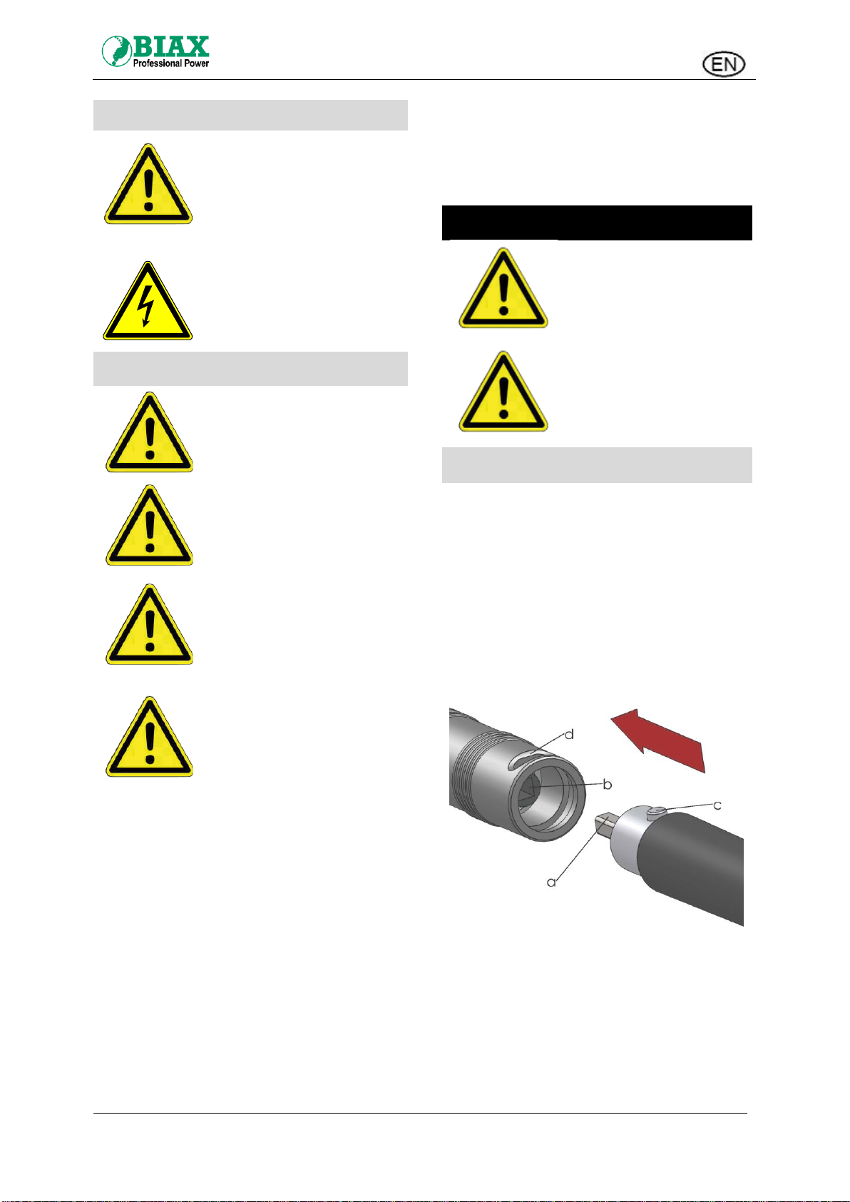
Assembly of the handpiece
The handpiece is equipped at the interface to the
flexible shaft with a square connection.
Place the square or Mini Z shaft (a) of the
flexible shaft in the socket (b) of the
handpiece. Push the handpiece and the
flexible Shaft together. The spring knob (c)
of the shaft must lock in the tool hand
recess (d).
For disassembling, depress spring knob
(c) and remove handpiece.
Fig. 1: Assembly of the handpiece on the shaft

Translation of the original assembly instructions
- 9 -
Changing the Tool
Only use properly fitting, undamaged open-end
wrenches to change the tools because the collet
and the spindle will be damaged otherwise.
There are various tool clamping systems,
depending on the handpiece:
Tool change with collet ZG 4
Fig. 2: Tool change with collet ZG 4
For handpiece with collet ZG 4 installed, the tool
change is carried out using the supplied wrenches.
Hold onto the spindle with the wrench (f) and open
or close the collet using the second wrench (e).
Tool change with collet ZG1A
Fig. 3: Tool change collet ZG1A
For hand pieces with collet type ZG1A, tool change
is carried out with the retaining pin (g) supplied and
key (h).
Insert the retaining pin (g) in the hole (i) and hold
the spindle. Then open or close the collet with the
key (h).
The retaining pin must be
removed from the hand piece
before switching on the prime¬
mover; otherwise, there will be
damage to the flexible shaft.
The minimum clamping length
of the shaft must not be
undershot. Observe the
specifications of the tool
manufacturer.
hold
OPEN
CLOSE
g
h
OPEN
CLOSE
i
This manual suits for next models
4
Table of contents
Languages:
Other BIAX Tools manuals


