aldes C.Axpir Initia User manual

C.Axpir Initia
C.Axpir Comfort
Notice d’installation
FR
Installation instructions
EN
Installationsanleitung
DE
Installatie-instructies
NL
Manual de instalación
ES
Manuale di installazione
IT

2
FÉLICITATIONS POUR VOTRE ACHAT DU SYSTÈME D'ASPIRATION
CENTRALISÉE DE POUSSIÈRES D’ALDES.
Ce manuel concerne les centrales d’aspiration Aldes C.Axpir Initia et C.Axpir Comfort, destinées à un usage
domestique. Veuillez lire attentivement ce manuel avant de commencer l'installation. Le manuel d'utilisation
et de maintenance de la centrale est inclus dans l'emballage. Veuillez suivre toutes les réglementations
ocielles en matière de conception et d'installation. Vous pouvez garantir le fonctionnement, l'ecacité et
la durée de vie de votre système d’aspiration centralisée de poussières en suivant toutes les instructions et
en utilisant uniquement des pièces et fournitures de marque Aldes. L'installateur doit s’assurer, pour chaque
situation, que les détails spéciés dans les instructions sont adaptés aux conditions de fonctionnement
Les centrales C.Axpir Initia et C.Axpir Comfort sont des aspirateurs sans sac (système de ltration cyclonique). Le kit
de sac à poussière et le sac à poussière peuvent être ajoutés en option (voir le manuel d'utilisation).
C.AXPIR COMFORT C.AXPIR INITIA
Caractéristiques C.Axpir
Comfort Caractéristiques C.Axpir
Initia
Référence (C.Axpir Comfort + set de nettoyage) 11071139 Référence (C.Axpir Initia + set de nettoyage) 11071138
Puissance (W) 1600 Puissance (W) 1300
Efcacité maximale (Air Watts) 680 Efcacité maximale (Air Watts) 520
Dépression (mm H2O) 3000 Dépression (mm H2O) 2800
Débit maxi. d’air (m3/h) 230 Débit maxi. d’air (m3/h) 217
Alimentation 230V - mono -
50Hz Alimentation 230V - mono -
50Hz
Pression acoustique à 3 m, en champ libre (dB(A)) 64 Pression acoustique mesurée en champ libre (3m, en dB(A)) 64
Poids (Kg) 8,5 Poids (Kg) 7
Volume de la cuve (L) 20 Volume de la cuve (L) 14
Indice de protection IPx0 Indice de protection IPx4
Distance maximale autorisée à la prise la plus éloignée (m) 45 Distance maximale autorisée à la prise la plus éloignée (m) 30
575 mm
780 mm
345 mm
375 mm
FR
3
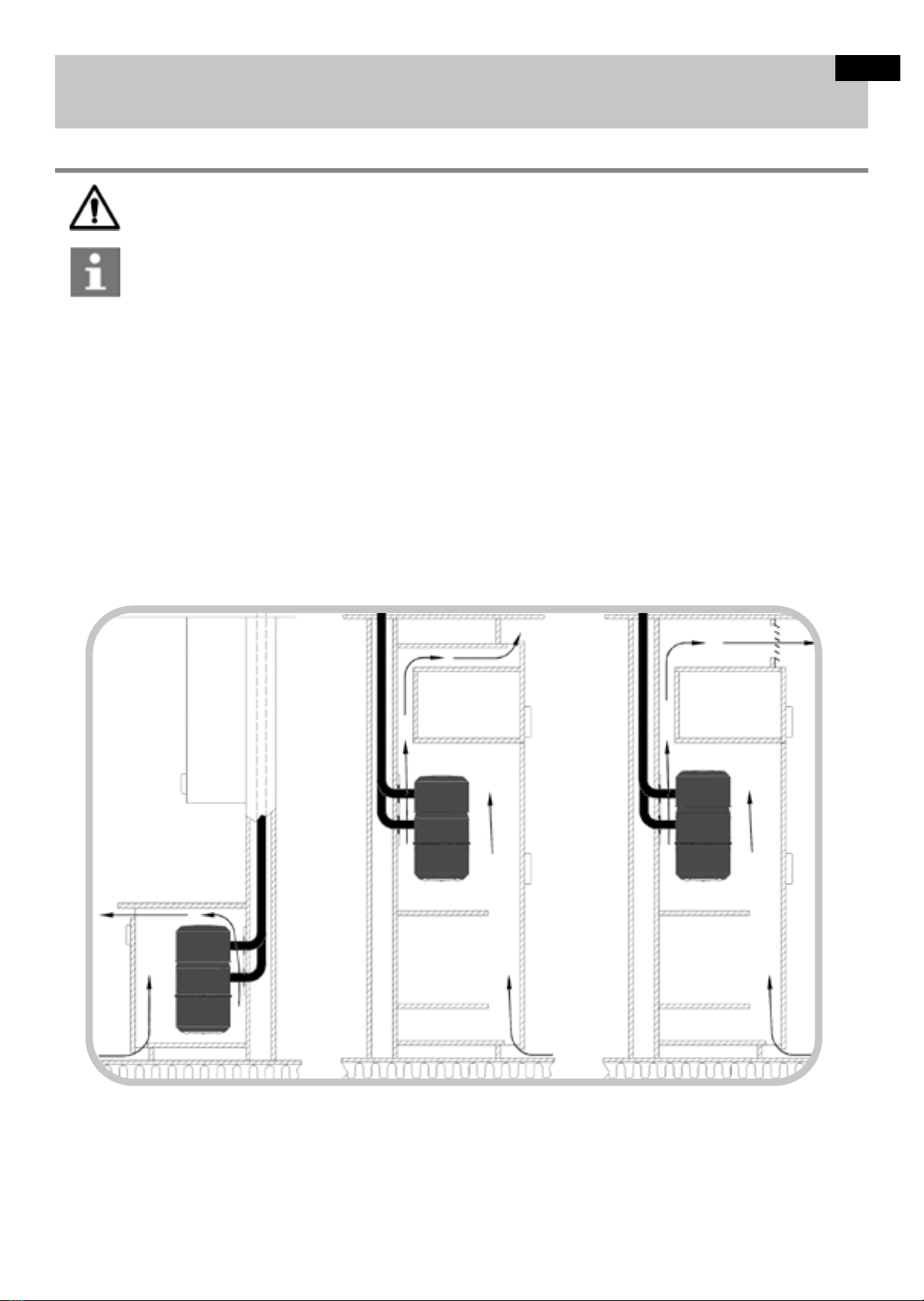
ESPACE D'INSTALLATION DE LA CENTRALE
Les centrales doivent être installées dans des espaces tempérés. Ne les installez pas dans un espace où la température peut descendre en dessous
de +5 ºC ou monter au-dessus de +35 °C, même lorsque l'appareil fonctionne. Le câble de raccordement des centrales mesure environ 1 mètre de
long et est connecté à une prise 230 V protégée par un disjoncteur 16 A. La chaleur du moteur de la centrale est libérée dans l'espace d'installation. Il
convient donc de s'assurer que l'air autour de la centrale ne stagne pas et que la ventilation dans l'espace d'installation fonctionne. Lors du choix d’un
modèle de centrale, la longueur du réseau entre la centrale et la prise d’aspiration la plus éloignée est la plus importante (voir les caractéristiques
des unités).
Les centrales C.Axpir Initia et C.Axpir Comfort sont adaptées à une installation en placard, à condition que la sortie de l’aspirateur centralisé soit
connectée à un système de refoulement pour diriger l'air évacué vers l'extérieur (kit de refoulement à commander séparément, réf. 11071182). La
circulation de l'air de ventilation étant bloquée dans les installations en placard, vous devez faire des trous d'air de ventilation dans le placard au
même niveau que le bas de la centrale ou en dessous, ainsi qu'au-dessus de la centrale et sur toutes les étagères intermédiaires. La taille minimale
requise est de 6 x Ø 50 mm ou 30 x 400 mm ou la largeur de la porte. La largeur libre minimale du placard doit être de 450 mm, la hauteur minimale
de 700 mm et la profondeur minimale de 450 mm. Vous ne devez pas couvrir les orices de ventilation.
Faites en sorte que le tuyau de refoulement soit éloigné de la centrale. Fixez un silencieux (disponible en accessoire) sur le tuyau de refoulement.
Le silencieux fonctionne mieux lorsqu’il est installé le plus près possible de l’extrémité du réseau de refoulement. N’installez pas le silencieux côté
aspiration du système.
Danger :
Risque d'incendie
Il est interdit de stocker des matières inammables ou corrosives ou de les manipuler dans les mêmes locaux que la centrale.
Observation :
Le tuyau d'extraction doit être équipé d'un silencieux.
FR

4
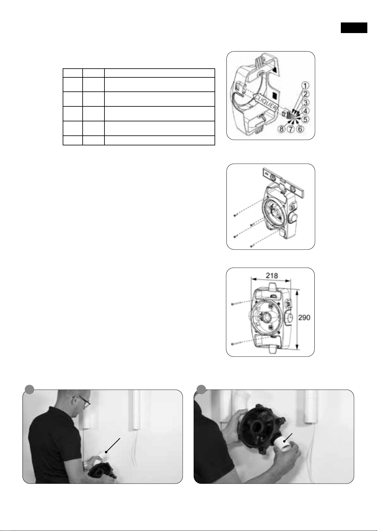
INSTALLATION DU BERCEAU MURAL
Laissez susamment d'espace pour la centrale autour du berceau mural.
Installez le berceau mural sur la surface du mur. Le mur d'installation du berceau mural
doit être droit. Utilisez un niveau à bulle pour vous en assurer. Si nécessaire, le mur
peut être redressé avec un panneau de montage supplémentaire.
Laissez des marges susantes sur les ls basse tension.
Modèle A (mm)
C.Axpir Initia 479
C.Axpir Comfort 684
Conseil pour une installation plus facile :
Si la centrale doit être installée dans un placard
intérieure du berceau mural avant d'installer
cette partie intérieure sur le mur.
1. Assurez-vous que les côtés entrée et sortie de la tuyauterie menant à la centrale
se trouvent du bon côté du berceau mural.
La partie intérieure du berceau mural peut être installée dans les deux sens.
2. Alignez la partie intérieure du berceau mural verticalement sur le mur, avec
une déviation maximale de +-5 degrés.
3. Fixez solidement la partie intérieure du berceau mural à la structure du mur
à l'aide de vis (4,2x50 mm TX20). Utilisez des chevilles si nécessaire (chevilles
6 x 30).
FR
5
4. Branchez les ls basse tension sur le connecteur du berceau mural
conformément au tableau ci-dessous.
8. Raccordement au réseau
Utilisez les pattes de xation sur le cadre extérieur du berceau mural pour
une xation supplémentaire, si nécessaire.
(En cas de montage sur un poteau de cloison, par exemple. Vis non
comprises dans la livraison).
Pour l'installation standard, seules les raccordements des câbles
basse tension (n°4 et n°5) sont utilisés.
5. Raccordez le connecteur basse tension au cadre extérieur du berceau mural.
6. Placez le cadre extérieur du berceau mural verticalement sur la partie intérieure
du berceau mural.
7. Fixez solidement la cadre extérieur du berceau mural à la partie intérieure à
l'aide de vis (5x20 mm TX20).
1 GND Terre. Ne pas utiliser
2AHU1 Contact sec hors tension
24 Vca/cc 1 A. (C.Axpir Initia uniquement)
3AHU2 Contact sec hors tension
24 Vca/cc 1 A. (C.Axpir Initia uniquement)
4SW2 Câbles basse tension (contrôle de la prise
d’aspiration)
5SW1 Câbles basse tension (contrôle de la prise
d’aspiration)
6/7/8 N/A Ne pas utiliser
côté entrée
2
de minimum 45 mm
sortie
FR

6
3 4
côté entrée et sortie
Colliers de serrage
Conseil pour une installation plus facile
2
Conduits
Pièces de transformation
Compatible avec les
conduits de diamètre
pièces de transformation
fournies)
Vissage des colliers
de serrage
FR
7
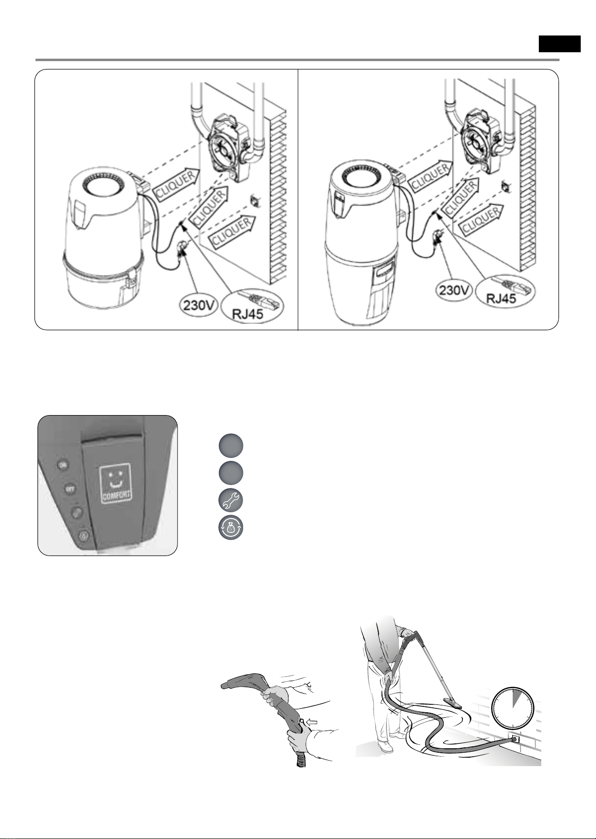
Bouton ON - Démarrage de l'unité
Bouton OFF - Arrêt de l'unité
LED - Alerte de maintenance ou de fuite dans le réseau
LED - Cuve ou sac de poussières plein
1. Installez la centrale sur le berceau mural.
2. Connectez le l basse tension RJ45 de la centrale à la borne basse tension RJ45 du berceau mural.
3. Branchez le cordon d’alimentation à la prise de courant.
4. Vériez que le système fonctionne correctement en démarrant la centrale à partir d’une prise d’aspiration (C.Axpir Initia).
5. Mise en service de C.Axpir Comfort
1. Raccordez le tuyau à une prise d’aspiration (pas à la prise d’aspiration de service intégrée à la centrale).
2. Secouez légèrement le tuyau. L'unité devrait démarrer dans les 5 s.
3. Appuyez sur le bouton de la vanne d'arrêt située sur la poignée.
4. Si le démarrage et l'arrêt sont réussis, la centrale est prête à être utilisée.
5. En cas d'échec, reportez-vous au paragraphe 5C.
INSTALLATION DES CENTRALES D’ASPIRATION
ON
OFF
DÉMARRER ARRÊTER !
CLIQUER
DÉMARRER ARRÊTER !
CLIQUER
5 s
FR

8
Testez le réseau, toutes les prises d’aspiration étant fermées.
1. Maintenez le bouton OFF enfoncé jusqu'à ce que la LED de maintenance s'allume en vert.
2. Relâchez le bouton OFF, réappuyez sur OFF puis sur ON pour lancer le test de réseau.
3. Après le test, la LED de maintenance s'allume :
- Vert : l'étanchéité du réseau est bonne.
- Orange : l'étanchéité du réseau n'est pas mauvaise.
- Rouge : fuite détectée. Dans ce cas, la centrale refuse de fonctionner et une action corrective sur les conduits est nécessaire.
La sensibilité de démarrage du système est réglable sur une échelle de 1 à 10. Plus la valeur est importante, plus la sensibilité est élevée. La
sensibilité du système est réglée par défaut sur 5, ce qui convient parfaitement à la plupart des installations.
Après avoir vérié l'étanchéité de la tuyauterie :
- si la centrale eectue des démarrages intempestifs, diminuer la sensibilité du système,
- si la centrale ne démarre pas, augmenter la sensibilité du système.
Ajustez la sensibilité du système :
1. Maintenez le bouton OFF enfoncé jusqu'à ce que la LED de maintenance s'allume en vert.
2. Relâchez le bouton OFF, puis appuyez sur le bouton ON pour faire clignoter la LED de maintenance.
- Le nombre de clignotements donne la valeur actuelle de la sensibilité (5 par défaut).
3. Réglez la sensibilité à l'aide des boutons ON / OFF :
- En appuyant sur le bouton ON, la sensibilité augmente d'une valeur.
- En appuyant sur le bouton OFF, la sensibilité diminue d'une valeur.
- Pour valider votre choix, ne touchez pas aux boutons et attendez environ 30 secondes que le système enregistre les nouveaux
paramètres souhaités.
FR

9
FR
NOTES

10
CONGRATULATIONS ON PURCHASING THE ALDES
CENTRAL VACUUM CLEANING SYSTEM.
This manual pertains to Aldes C.Axpir Initia and C.Axpir Comfort central vacuum units, intended for domestic
use. Please read this manual carefully before starting the installation. The usage and maintenance manual
for the central unit is always included in the packaging. Please follow all ocial regulations in design and
installation. You can ensure the operation, eciency and long service life of your central vacuum cleaning
system by following all instructions and by only using original Aldes parts and supplies. The installer must
consider whether the details specied in the instructions are suited to the operating conditions in each case.
The C.Axpir Initia and C.Axpir Comfort units are bagless vacuum cleaners (cyclonic ltration system). Dust bag kit
and dust bag can be added as an option (see user manual).
C.AXPIR COMFORT C.AXPIR INITIA
Characteristics C.Axpir
Comfort Characteristics C.Axpir
Initia
Reference (C.Axpir Comfort + Cleaning set) 11071139 Reference (C.Axpir Initia + Cleaning set) 11071138
Power (W) 1600 Power (W) 1300
Max Efciency (Air Watts) 680 Max Efciency (Air Watts) 520
Depression (mm H2O) 3000 Depression (mm H2O) 2800
Max air ow (m3/h) 230 Max air ow (m3/h) 217
Supply 230 V - mono -
50 Hz Supply 230 V - mono -
50 Hz
Sound pressure measured in free eld (3 m, in dB(A)) 64 Sound pressure measured in free eld (3 m, in dB(A)) 64
Weight (Kg) 8.5 Weight (Kg) 7
Dust tank volume (L) 20 Dust tank volume (L) 14
Casing class IPx0 Casing class IPx4
Maximum pipe length (m) 45 Maximum pipe length (m) 30
575 mm
780 mm
345 mm
375 mm
EN
Other manuals for C.Axpir Initia
1
This manual suits for next models
3
Table of contents
Languages:
Other aldes Vacuum Cleaner manuals


