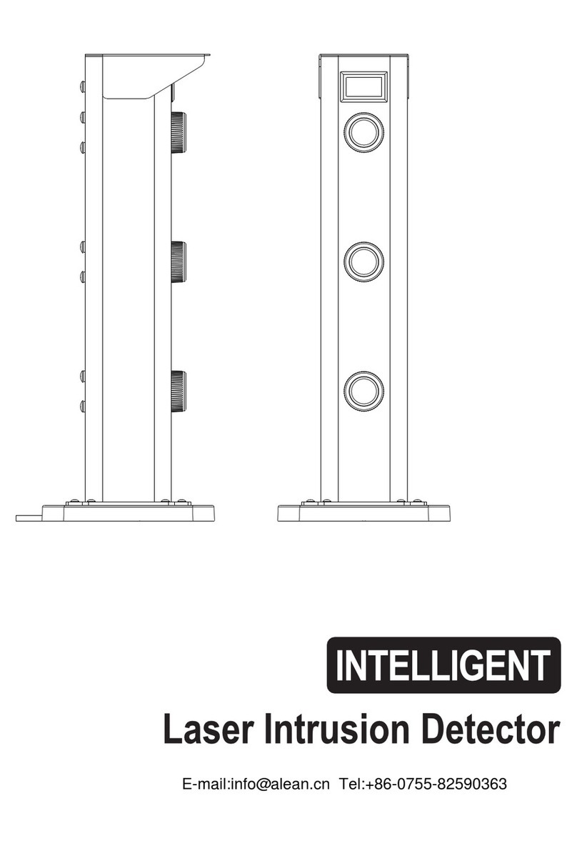
TRIPLICATE PHOTOELECTRIC BEAM DETECTORTRIPLICATE PHOTOELECTRIC BEAM DETECTOR
User Manual
ALARM red is on whencreate alarm activation
LEVEL becomes brighter when more LEDs light
in alignment.
GOOD (green) ison when beamsare aligned,
and off when beams arenot well aligned.
Where blocks (suchas trees orplace for hangingclothes)
are between the receiver and the sender while installing..
Where installation base
is unstable.
Where the sunlightlight and automobile headlight
Setting notice
Mounting Height
The optical axis can be adjusted within
00
horizontal direction +90 , vertical direction +10
00
Horizontal direction +180(+ 90)
Shine directly.
Spread of beam
Protection distance
In case of using mangygroups of detectors
when long distance protectionto avoid the
mutual disturbance of light beams.
Cover
Parts description
Connection Terminal
LED indicators
Voltage Testing
Hole
Lens
Beam interruption
Time Adjustment
Horizontal Adjusting
Dial
Beam alignment
Level Indicator
Cover locking screw
VerticalAdjustable
Screw
Tamper
Wiring Hole
After alignment, thefifth alignment LEDof receiver
must be on,otherwise you haveto continue the
alignment. Recommend the7th or moreLED
indicators on.
Power (green) ison when the beam is transmitting
The wiring distance
Pole mounting:
1.Break out the wire hole on
the bracket then pull out the
wires.
2.Remove the cover
3.Fix the base plate on the bracket.
Back to back installation (Refer to the figure below.)
Mounting Method
4 Connecting wires tothe terminal.
Power
Power
FreeFree
Free
Tamper switch
Tamper switch
Transmitter
Receiver
Alarm output
2
0.5mm ( 0.8)
0.75mm ( 1.0)
2
1.25mm ( 1.2)
2.0mm ( 1.6)
DC12VDiameter Voltage
300m 600m
400m 800m
700m
1000m 2000m
1400m
DV24V
1. Loosen thefixed screw
and remove thecover. 2.Break out theknock-out and pull
wire through.
3.Mount the detectoron the wall.
Knockout
5. Fix the cover after beam alignment is adjusted .
1.Remove the cover, apply thepower.
2.Adjust the horizontaladjustment dial andvertical adjustment screw,
to make themost LEDs ON,the 5th LEDmust be ON,otherwise
please readjust. Morethan 7 litLEDs is recommended.
Vertical Adjustment Screw
Beam Adjustment
The more LED indicators light, thehigher
of the precision of thebeam alignment would be.
Horizontal Adjustment Dial
Left
Right
.
Voltage Meter testing method:
1. Insert theprobes of thevoltage meter to the testinghole (Pay attentionto the polarity)
2. Adjust the dial horizontally and vertically to obtain the largest voltage.
3. If 1.2V orabove cannot be acquired, you have to continue to adjust. Top output
can be upto 1.8V(1.5v orabove is recommendedto prevent falsealarm in severe
environment ).
After the optical axis angle alignment,the 5th
LED indicator ofreceiver must be on,otherwise
you have tocontinue the alignment.
Recommend the 7thor more LED indicators light.
Caution
Beam interruption time adjustment
Condition Indication
Transmitter
Receiver
Transmitting Green LED isON
Watching
Alarm
GOOD-LEVEL Indication is ON
Alarm indication lamp is ON
Operation confirmation
After installation, confirmcorrect
operation by suitablewalk tests.
Refer to theLED indication ofthe
right form duringthe walking test.
Troubleshooting
Symptom Possible Cause Remedy
Transmitter LED dose not light.
Receiver LED dose not light.
The alarm indicationlamp of receiver
is always on.
Intermittent alarm
Checking wiring andconnection spot.
Check the powersupply and wiring.
Improper voltage supplied. Check the powersupply and wiring.
Improper voltage supplied.
Alarm LED dose not light, even
when beams are blocked.
When the beamsare blocked,
the receiver LEDlights is ON,
but not alarm.
3. Shading light time is too short.
2. 3 beams are not interdicted
Simultaneously.
1.Beams reflect to the receiver by
other objects.
1. Remove the reflecting object or
change optical axis direction.
2. Shade 3 beam
3. Prolong the shading time.
1.Wring is short circuit.
2. Wiring pointis not good.
1. Optical axis is not properly adjusted.
2. There are blocks between the
transmitter and receiver.
3. The detector cover or strained slick
are dirty.
1. Adjust the optical axis.
2. Remove the blocks.
3. Polish with the soft cloth.
1. Bad wiring.
2. Supplied voltage can’t reach 12V
3. Movable blocks between
the transmitter and the receiver.
4. The installation base is unstable.
5. Improper lens direction.
6. Blocked by other moving objects.
7.The interruption time is too short.
8.5 Lens do not light when uncover
1. Check wiring.
2. Check the power supply.
3. Remove the blocks or relocate.
4. Fix the mounting.
5. Adjust the lens direction.
6. Adjust interruption time or
change installing position.
7.Readjust interruption time.
8.Readjust the lens direction to
obtain fine alignment.
Specification
Mounting, bracket and measurement
Range Outdoor 50m 100m
75m
225m
150m
125m
180m 200m 250m
750m
540m 600m
450m
375m
300m
150m
Indoor
Pulsed infrared triplicate beams
Options
DC12~24V/AC11~18V
70mA max 80mA max 90mA max 100mA max
Wall or pole
PC Resin(Black)
1900g(Both transmitter and receiver)
5%-95% relative humidity
20 (+10 )vertical, 180 (+90 )horizontal
-25 ~+55
N.C (DC24V, 0.5Amax)
NO.NC relay (AC/DC30V 0.5A max)
50~700msec(selectable)
Interruption period
Power input
Current consumption
Alarm period
Alarm output
Tamper switch
Environment humidity
Alignment angle
Mounting
Weight
Appearance
Operating temperature
Beam characteristics
Heater
2sec(+1)nominal
Receiver
Receiver
Receiver
Receiver
Transmitter
Transmitter
Transmitter
Transmitter
0
Vertical direction +10
50m 1.5m
75m 2.3m
100m 3.0m
125m 3.8m
150m 4.5m
180m 5.4m
200m 6.0m
250m 7.5m
Protection distance
Dispersion
15mm
Caution
1
5
6
7
8
9
2
3
4
DC 10V
1. 50msec
3. 306msec 4. 408msec 5. 700msec
2. 80msec
285mm
L-Shaped Backet
80 75mm
T-Shaped Backet
External measurementBracketRecommend mounting
100 120mm
T-100
00 120mm
T- 00
I-Shaped Bracket
100mm
I-100
00mm
I- 00
PHOTOELECTRIC DETECTOR
DISTANCE
m


