manuals.online logo
Brands
  1. Home
  2. •
  3. Brands
  4. •
  5. Alean
  6. •
  7. Security Sensor
  8. •
  9. Alean SM-HWDS-Z11 User manual

Alean SM-HWDS-Z11 User manual

E-mail:[email protected] Tel:+86-0755-82590363
1st digit 2nd digit 3rd digit 4th digit Way of enter Way of ex it
Normal working
condition
Enter normal working mode when no
operation or ex it operation
Debugging
alignment model
Display C Display 0
Press the function adjustment button for
more than 3 seconds to enter the
alignment mode
Press again to ex it
when last beam is
displayed
Debugging
alignment
model(Visible light)
Display L Display 0
Press the function adjustment button for
more than 10 seconds to enter the
alignment mode (Note: Visible light
aligner and invisible light aligner cannot
Press again to ex it
when last beam is
displayed
0000 means normal working condition
01~12 indicates the current beam.If 01 is
displayed,it means that the current aligning
beam is the 1st beam,and so on.
01~12 indicates the current beam.If 01 is
displayed,it means that the current aligning
beam is the 1st beam,and so on.
1st digit 2nd digit 3rd digit 4th digit Way of enter Way of ex it
Normal working
condition
Display 0
Enter normal working mode
when no operation or ex it
operation
Debugging alignment
mode
Display C
Press the function
adjustment button for more
than 3 seconds to enter the
alignment mode
Press again to ex it
when last beam is
displayed
Trigger condition
setting
Display E
Press the function
adjustment button 2 times to
enter this mode
Response time
setting
Display F
Press the function
adjustment button 3 times to
enter this mode
Bypass Laser Beam
setting
Display H
Keep pressing function
button >10seconds, and then
into bypass mode.
Detector will auto
play from 01 beam to
the last beam and
then auto ex it.
(1) 01~12: The current laser beam which need ON/OFF bypass.
After into programming, it will auto play from 01 beam to 12beams
till ex it.(2) Digit display of beam number blinking, means that
beam is bypass status.(3) Digit display of beam number keeping
lighting,means that beam is activated mode.(4) If need change
the laser beam status, just click the function button once when
auto playing the beams on the LED Digital display.
1~12 indicates the current beam. If 1 is
displayed, the beam with the lowest signal
is 1 or the current 1 beam is triggered.
0 ~ 9 indicates the
current beam signal
intensity, 9 is the
strongest signal, and
0 is the weakest
signal.
01-12 indicates the current beam. If 01 is
displayed, it means that the current
aligning beam is the first beam, and so on
001~012 indicate the current trigger conditions. If 001 is
displayed, it means that the current trigger condition is to block 1
beam to trigger the alarm, and so on. If the current display is 003
when setting, it means that the current trigger condition is to
block 3 beams to trigger the alarm.
Automatically save
and ex it after 5
seconds without any
operation, return to
normal working
mode
050, 100, 300, and 700 indicate that the alarm response time is
50ms, 100ms, 300ms and 700ms. If 50 is displayed, the trigger
response time is currently set to 50ms, and so on.
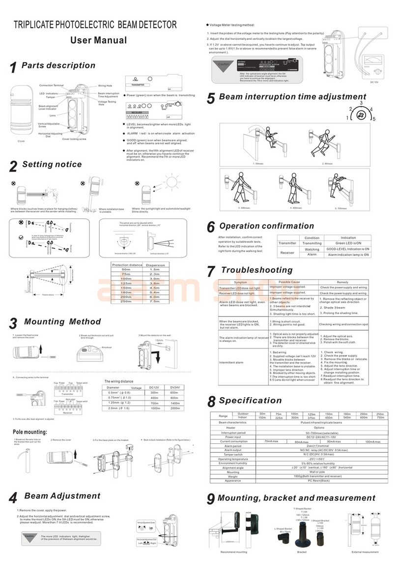
Failure (phenomenon) Cause Countermeasure
1. No voltage on power line 1. Check the power adapter
2. Open or short circuit 2. Check the line
3. Ex ceeding the specified voltage 3. Replace the adapter
4. The power line ex ceeds the specified length 4. Replace the power line
1. There are reflectors or other transmitters entering
the receiver
1. Remove reflectors or turn off other emitters and
realign
2. The beam is not blacked 2. Ensure the beam is completely blocked
3. The blocking time is setting too long 3. Reduced blocking time
4. Alarm output wiring is incorrect 4. Check the receiver terminals and output wiring
1. Beams are not aligned and the optical ax es do
not coincide
1. Recalibrate the optical ax is
2. Obstacles between transmitter and receiver 2. Check the obstacles
3. The transmitter or receiver housing is very dirty
or covered with snow, frost, or ice
3. Clean the cover
4. No transmitter output
4. Check the transmitter power supply current and
wiring
1. Wiring or power supply fluctuations,line
corrosion
1. Replace power supply, current and wiring
2. There are moving obstacles, such as birds,
newspapers, leaves, etc.
2. Change installation location
3. The installation base is unstable
3. Reinforce the base or choose a solid installation
base
4. Not perfectly aligned 4. Recalibrate the optical ax is
Indicator is off after power on
The alarm indicator does not turn on after the
beam is completely blocked, and no alarm
output.
The beam is not blocked, the alarm indicator is
always on, and there is alarm output
False alarm

Other Alean Security Sensor manuals

Alean ABT-20 User manual

Alean

Alean ABT-20 User manual

Alean ABE series User manual

Alean

Alean ABE series User manual

Popular Security Sensor manuals by other brands

Tyco WS4933 Series Installation and operating instructions

Tyco

Tyco WS4933 Series Installation and operating instructions

THORLABS PDAPC1 user guide

THORLABS

THORLABS PDAPC1 user guide

Cytronix LSS05 user manual

Cytronix

Cytronix LSS05 user manual

Crow SH-MAG-SHOCK-8F instruction manual

Crow

Crow SH-MAG-SHOCK-8F instruction manual

Defort DMM-20D-RF user manual

Defort

Defort DMM-20D-RF user manual

TRIGA TR-B300-6 Installation and maintenance instructions

TRIGA

TRIGA TR-B300-6 Installation and maintenance instructions

Comunello Automation DART SLIM SYNC Installation and user manual

Comunello Automation

Comunello Automation DART SLIM SYNC Installation and user manual

Chamberlain CWPIPR manual

Chamberlain

Chamberlain CWPIPR manual

GEV NATALIA 10888 manual

GEV

GEV NATALIA 10888 manual

AMC IF800 installation manual

AMC

AMC IF800 installation manual

Schwaiger ZigBee ZHS21 user manual

Schwaiger

Schwaiger ZigBee ZHS21 user manual

Metz Mecablitz S30 operating instructions

Metz

Metz Mecablitz S30 operating instructions

AirTest IAQEye TR8910 user manual

AirTest

AirTest IAQEye TR8910 user manual

Ksenia unum wls installation guide

Ksenia

Ksenia unum wls installation guide

ESYLUX MD 120 User instructions

ESYLUX

ESYLUX MD 120 User instructions

LST 2351TEM Specification sheet

LST

LST 2351TEM Specification sheet

Infinite L-COM SRAQ-G009 user guide

Infinite

Infinite L-COM SRAQ-G009 user guide

TFA 43.2034 instruction manual

TFA

TFA 43.2034 instruction manual

manuals.online logo
manuals.online logoBrands
  • About & Mission
  • Contact us
  • Privacy Policy
  • Terms and Conditions

Copyright 2025 Manuals.Online. All Rights Reserved.