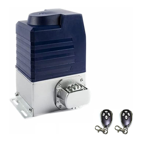
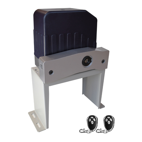
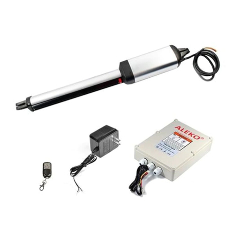
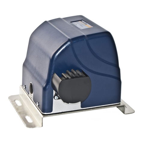
Aleko LOCKMASTER L110C User manual

ALEKO AC-2000 SLIDING GATE OPERATOR
1
OUTLINE
1. Important safety information…………………3
2. Main functions…………………………………3
3. Technical parameters…………………………3
4. Packing list ……………………………………3
5. Installation……………………………………5
6. Connect the wires ……………………………9
7. Adjustment……………………………………9
8. Maintenance…………………………………10

ALEKO AC-2000 SLIDING GATE OPERATOR
2
1. Important safety information
Carefully read and follow all safety precaution and warnings before attempting to install and
use this operator, incorrect installation can lead to severe injury.
The gate operator should be installed by a qualified technician; otherwise, serious
personal injury or property damage may occur.
The automatic gate operator must be grounded.
When opening or closing the gate, do not attempt to walk or drive through the gate.
Children should not be allowed to play near or operate automatic gates.
Install the gate operator on the inside of the property, DO NOT install it on the outside of
the property where the public has access to it.
Be careful when in close proximity to moving parts where hands or fingers could be
pinched.
The operator should be switched off before repairing it or opening its cover.
2. Main functions
The gate operator is used to drive the sliding gate, it is capable of overwork in short time.
When overloading, it has electrical and mechanical double protections to ensure operating
safety. In case of power failure, a release key allows to loosen the clutch to move the gate
manually.
3. Technical parameters
epyT
Limit switch Magnetic limit switch Spring limit switch
zH06,011CAylppusrewoP
Output torque (Max.) 15N·m
mpr0561deepsrotoM
03:1oitarnoitcudeR
Environmental temperature -10ºC to +55ºC
4.Packing list
After receiving the product, you should make an unpack-inspection, in which you should check
whether the product was damaged. If you have any problem please contact dealer.
AC-2000 gate operator packing list
ytitnauQmetI.oN
1rotarepoetaG1
2yekesaeleR2
1)yrosseccaeraps(esabrotarepO3
2rabnethgiT4
2tekcarbtengaM5
1revoctekcorpS6
7 Screw for mounting driven sprocket bracket (M8X16) 4
4tunhtiwtlobrohcnA8
9 Driven sprocket bracket (left side & right side) 2
10 Magnet 2
11 Anchor 4
AC-2000 AC-2000

Residential Sliding Gate
Operator
Tools you will need
During assembly and installation of your opener, the instructions will call for the use of
various tools shown below. Other tools may be required as needed for the installation of
the concrete pad and electrical connection.
Table 3 Required Tools for Installation
Screwdriver Tape Measure Electric Drill Level
File Wrenches Multimeter Pliers Allen Wrenches
Wire Strippers Wire Cutter Adjustable Wrench Socket Wrench
AC-2000
3

ALEKO AC-2000 SLIDING GATE OPERATOR
4
Fig.1 AC-2000 accessories
AC-2000 gate operator packing list
ytitnauQmetI.oN
1Gate operator 1
2Release key 2
3Operator base (spare accessory) 1
4Tighten bar 2
5Block bracket 2
6Sprocket cover 1
7Screw for mounting driven sprocket bracket (M8X16) 4
8Anchor bolt with nut 4
9Driven sprocket bracket (left side & right side) 2
10 Block 2
11 Anchor 4

ALEKO AC-2000 SLIDING GATE OPERATOR
5
Fig.2 AC-2000 accessories
5. Installation
The AC-2000 Chain-driven Gate Operator operates by forcing a straight piece of chain.
This length of chain is extended between two chain brackets located at opposite ends of the
gate. The entire configuration is shown in the diagram below.
Fig.3 AC-2000

L110C/L110 SLIDING GATE OPERATOR
6
Fig.4 L110
Conduit
In order to protect the wires, conduit must be preset into the concrete when it is poured. Wires
within the conduit shall be located or protected so that no damage can result from contact with
any rough or sharp part.
Concrete pad
The base unit of the gate operator requires a concrete pad in order to maintain proper stability.
The concrete pad should be approximately 300mm x 260mm x120mm deep in order to provide
for adequate operation.
Anchors
You can use the anchor bolts, anchors, washers, and nuts. These anchors must be set into the
concrete when it is poured, or you can use wedge anchors.
Chain
Sprocket bracket
Installation 2
Installation 1
Anchor
Anchor bolt
Tighten bar
Conduit
Fig.5

ALEKO AC-2000 SLIDING GATE OPERATOR
7
Driven sprocket bracket
Fix the driven sprocket bracket on both sides of the operator.
Operator
In locations where ground freeze is possible, mount the gate operator as shown in Fig.5
installation 1 or installation 2. Check the operator and make sure it is lined up with the gate.
Chain Brackets
Use the appropriate bolts to attach the chain bracket to the frame of the gate. If the gate is of
square frame style, use the square bolts shown.
Spring washer (Φ8)
Plain washer (Φ8)
"L" bracket
Square bolt
Nut (M8)
Chain bolt
Master link
Nut (M6)
Spring washer (Φ6)
Plain washer (Φ6)
Gate Square frame
Fig.6
If the gate is of round frame style, use the round bolts shown.
Round bolt
"L" bracket
Plain washer (Ф8)
Spring washer (Ф8)
Nut (M8)
Chain bolt
Master link
Nut (M6)
Spring washer (Ф6)
Plain washer (Ф6)
Gate Round frame
Fig.7
Chain
Close the gate and attach a chain bolt to the chain using enclosure master links. Tighten the
chain bolt to the bracket with washers and nuts. Pull the chain through the sprockets to the
other chain bracket at the opposite end of the gate see Fig.9. Connect the other end of the
chain and the chain bolt, and then tighten the chain bolt to the chain bracket. Thread up the
chain by adjusting the chain bolt. Cut the chain to length if necessary. Tighten the chain by
tightening the chain bolts at either end. See Fig.8.
Master link
Chain bolt
Chain
Fig.8

ALEKO AC-2000 SLIDING GATE OPERATOR
8
Drive sprocket
Driven sprocket
Driven sprocket
Fig.9
Sprocket cover
Mount the sprocket cover with screws.
Limit switch
AC-2000 -Magnets for limit (see Fig.10)
Install the magnet as shown in Fig.10 below. The magnet and limit switch are used to
control the position of the gate.
When the magnet is installed, release the gear clutch and push the sliding gate manually to
pre-determine the position. Fix the magnet bracket to the gate and then tighten the gear
clutch. The lower bracket is for open position and upper bracket is for close position.
Finally adjust the magnet to the proper position by moving the gate with the motor. The
magnet should be 10~15mm away from the magnetic limit switch. If it is too far away, the
switch will fail to work. Adjust the position of the magnet until the positions of the opening
and closing meet the requirement.
Please note the position of two magnet brackets (fixed plate) are different: one is
upper and another is lower. Verify and if necessary exchange the two brackets
position. Also if necessary exchange the limit switch wires CL (close) and OP
(open).
Release key
Gate operator
Gate
Upper and lower Magnets
Sprocket cover
Drive sprocket
Magnet bracket
Fig.10 AC-2000

ALEKO AC-2000 SLIDING GATE OPERATOR
9
AC-2000-Spring limit tch(see Fig.11)
To ensure safety, it is recommended to install limit devices at both ends of the gate to
prevent the gate from sliding out of the rails. The rails must be installed horizontally.
The spring limit switch and blocks are used to control the position of the gate.
When the block is installed, release the gear clutch with the key and push the sliding gate
manually to pre-determine the position, fix the block bracket to the gate and then tighten
the gear clutch with the key. Moving the gate electrically, adjust the block bracket to the
proper position until the position of the opening and closing meet the requirement.
Release key
Gate operator
Gate
Spring limit
switch and block
Block bracket
Fig.11 AC-2000
6. Connect the wires
Make sure that the power is OFF before making any electrical connections. Remove the cover
of the control box, perform the wiring and replace the cover again. (Refer to Fig.12)
Fig.12
7. Adjustment
Check the power supply, grounding and wiring before running the device.
Release the clutch with the key to determine whether or not the gate can be moved manually.
If everything is in good working order, engage the clutch with the key.
When engage the clutch with the key, be sure to close completely to prevent from damage.
Switch on the power and run the operator to ensure that the gate is sliding smoothly.
Adjust magnet or block position until the gate opened and closed properly at the limited
positions.

10
Setting of
the Control
Board
1. DIP Switches
The DIP switches are
used to set the limit
switch of the opener to
be NO or NC, auto close
time of the gate opener
and fast change the
open/close direction
which is determined by
the position of the gate
opener installed.
Setting of the Control Board
DIP Switch #1:Limit switch NC (normally closed) or NO (normally open)
DIP Switch #1:ON – NO / OFF –NC
This mode enables user to set the board to work with motor with NC or NO limit switch
NOTE: Factory default setting is NO
DIP Switch #2–#4: Auto close time of the gate opener
DIP Switch #2: ON – 12.5 Seconds OFF – 0 Seconds
DIP Switch #3: ON – 25 Seconds OFF – 0 Seconds
DIP Switch #4: ON – 45 Seconds OFF – 0 Seconds
NOTE: The auto-close function would be disabled if all 3 dip switches are turned to off (factory default
setting).

11
DIP Switch #5: Direction of gate opening.*
(* Direcon from the inside of the property where the opener is installed.)
DIP Switch #5: OFF – Opens to the right.
DIP Switch #5: ON – Opens to the left.
Note: Ifopening is to the left, the Limit Switch wires on the control board (yellow & red) need to
be reversed. The black wire stays the same.

12
DIP Switch #6: (NOT USED)
DIP Switch #7–#8: Remote Control Button (yellow & blue) Setting
DIP Switch #7: ON – Yellow Button is Working OFF – Yellow Button is Not Working
DIP Switch #8: ON – Blue Button is Working OFF –Blue Button is Not Working
2. Potentiometers
The left potentiometer is to adjust the CLOSE stall force of the gate opener. The right Potentiometer is used to
adjust the OPENstall force of the gate opener.
Turn the potentiometer clockwise to increase the stall force.
Turn the potentiometer counter-clockwise to decrease the stall force.

19
Test the reversing sensitivity
For the sake of safety, it is very important to test the reversing sensitivity as soon as the control board set is
finished.
The reversing sensitivity adjustment is inverse correlation with stall force adjustment in potentiometer 1 and
potentiometer 2. In other word, the stall force level is higher; the reversing sensitivity level is lower.
Put an immobile object along the gate path, and then operate the gate to strike it during the open and close
cycles. The gate must reverse as soon as object is struck with it. If the gate doesn’t reverse, please increase
the reversing sensitivity by turning the potentiometer in counter-clockwise direction. (Turning the stall force
potentiometer toward to “Light” position to increase the reversing sensitivity)
Note 1: If the sensitivity setting is too higher, the gate will stop or reverses very easy by itself
while there is little obstruction or resistance such as strong wind or heavy snow sometimes.
Note 2: Always check the gate reversing function every each time of control board set or
restart after power off.
How to learn or erase the remote
Learn the remote
Press and release the learn button, the BLUE LED light will be on, then press any button in the remote within
5 seconds, the BLUE LED light will go off. Now the remote has been learnt successfully.
Erase all the remote codes
Press and hold the learn button until the BLUE LED light goes off after flashing 5 times. Now all remote codes have
been erased.

Residential Sliding Gate OperatorAC1400
Optional Equipment Installation Procedures
O
O
O
O
O
O
O
O
O
O
O O
Blue
Brown
Black
White
Green
Brown
Red
Black
13

ALEKO AC-2000SLIDING GATE OPENER
14
11. Trouble Shooting
snoituloSsesuacelbissoPelbuorT
The wire connector terminal block
becomes loose.
Check wire connector terminal block make
sure it is plugged in terminal block 10 (X8).
The limit switch wire connector terminal
block becomes loose.
Check limit switch wire connector terminal
block make sure it is plugged in terminal
block 9 (X9).
Check the limit switch mode.
Motor only runs in one direction.
The electric component on the control
board such as Q2, Q91 or Q92 may be
damaged.
Replace the electric component Q2, Q91 or
Q92 (BTA16/600) or replace the board.
By pressing button 1(button 2 or button 3)
which has been programmed to open the
gate, press the same button again to stop
the gate in required position, but the gate
will auto-close immediately.
The auto-close time is too short. Reset the auto-close time. See Set auto-
close function section.
When you use button 4 of remote control
to open the gate, gate travels too short.
The width of pedestrian mode is too
narrow.
Reset the width of pedestrian mode. See Set
width of pedestrian mode section.
When you use button 4 of remote control
to open the gate, but the gate will auto-
close immediately.
The auto-close time of pedestrian mode
is too short.
Reset the auto-close time of pedestrian. See
Set auto-close function of pedestrian
mode section.
The limit switch wire connector terminal
block becomes loose.
Check the limit switch mode (see table 1 DIP
switch).
Connecting wires or terminal blocks are
too loose.
Check the connecting wires and terminal
blocks.
The electric component on the control
board such as Q2, Q91 or Q92 may be
damaged.
Replace the electric component Q2, Q91 or
Q92 (BTA16/600) or replace the board.
The gate will not open or close.
.NOsihctiwsrewoperusekaMFFOsihctiwsrewoP
The indicator light of remote control does
not light. Check the batteries on your remote control.
Remote control is not suitable for
receiver.
After making sure the codes are correct,
erase remote controls and then re-program
the codes in the device. See Adding extra
remote controls (learning) section.
Remote control does not work
Broken receive board Replace receive board.
The Force Adj. (VR1) is adjusted too
small.
Check the Force Adj. (VR1). Adjust VR1 to
increase force.
When you open the gate by using button
1(button 2 or button 3) which has been
programmed, gate will stop in mid-travel
or reverse before reaching the fully limit
position. .noitcurtsboehtevomeR.detcurtsbosietaG
The remote control operating distance is
too short. Signals are shielded by the gate.
Link a new antenna (1~1.2m BVR 0.75mm2
see parts list) to the old antenna. Then fix the
antenna on the wall vertically, make sure the
total height from the top of antenna to the
ground is approx. 1.5m.
The gate opens, but stops and will not
return.
1. Please note the two magnet brackets
(fixed plate) are different: one is higher
and another is lower. Please try to
exchange the two brackets position.
2. Please try to exchange the limit switch
wires CL (close) and OP (open).
There are two reed switches inside the
magnetic limit switch: one is upper and
another is lower. Maybe the magnet position
was installed in the middle so it inducts both
reed switches. Solution: adjust the magnet
upper or lower.
This manual suits for next models
1
Table of contents
Other Aleko Gate Opener manuals