Alena Energy BySolarPower BSP 5S User manual

Alena-energy.com Version: 1.2
SMART SOLAR INVERTER
SYSTEM
BSP 5S
USER MANUAL

ALENA ENERGY CO.,LTD
208, Nguyen Trai, 1 District, HCM City, Viet Nam
Tel: (+84) 28.39.2626.83 / Fax: (+84) 28.39.2626.82 / Email: [email protected] / www.alena-energy.com
TABLE OF CONTENTS
Information on this Manual .......................................................................................... 1
Validity
Scope
Target Group
Safety Instructions
Symbols
Introduction. .............................................................................................................. 3
Features
Product Overview
Installation ................................................................................................................ 6
Unpacking and Inspection
Preparation
Mounting the Unit
Battery Connection
AC Input/Output Connection
PV Connection
Final Assembly
Communication Connection
Dry Contact Signal
Operation ................................................................................................................ 14
Power ON/OFF
Operation and Display Panel
LCD Display Icons
LCD Setting
Display Setting
Operating Mode Description
Fault Reference Code:
Warning Indicator
Specifications .......................................................................................................... 32
Trouble Shooting ...................................................................................................... 36

ALENA ENERGY CO.,LTD
208, Nguyen Trai, 1 District, HCM City, Viet Nam
ĐT: (+84) 28.39.2626.83 / Fax: (+84) 28.39.2626.82 / Email: [email protected] / www.alena-energy.com
P a g e | 1
Information on this Manual
Validity
This manual is valid for the following devices:
Off grid solar inverter with MPPT controller, 5KVA – Model BSP 5S.27
Scope
This manual describes the assembly, installation, operation and troubleshooting of this unit. Please read
this manual carefully before installations and operations.
Target Group
This document is intended for qualified persons and end users. Tasks that do not require any particular qualification
can also be performed by end users. Qualified persons must have the following skills:
Knowledge of how an inverter works and is operated
Training in how to deal with the dangers and risks associated with installing and using electrical devices
and installations
Training in the installation and commissioning of electrical devices and installations.
Knowledge of the applicable standards and directives
Knowledge of and compliance with this document and all safety information
Safety Instructions
WARNING: This chapter contains important safety and operating instructions.
Read and keep this manual for future reference
1. CAUTION – Only qualified personnel can install this device with battery.
2. Before using the unit, read all instructions and caution marks on the unit, understand the batteries and all
appropriate sections of this manual.
3. CAUTION --To reduce risk of injury, charge only deep-cycle lead acid type rechargeable batteries. Other
types of batteries may burst, causing personal injury and damage
4. NEVER cause AC output and DC input short circuited. Do NOT connect to the mains when DC input short
circuits.
5. NEVER charge a frozen battery.
6. Do not disassemble the unit. Take it to a qualified service center when service or repair is required.
Incorrect re-assembly may result in a risk of electric shock or fire.
7. To reduce risk of electric shock, disconnect all wiring before attempting any maintenance or cleaning.
Turning off the unit will not reduce this risk.
8. Be very cautious when working with metal tools on or around batteries. A potential risk, such as dropping
a tool to spark or short circuit batteries or other electrical parts, could cause an explosion.
9. For optimum operation of this off grid solar inverter, please follow required spec to select appropriate
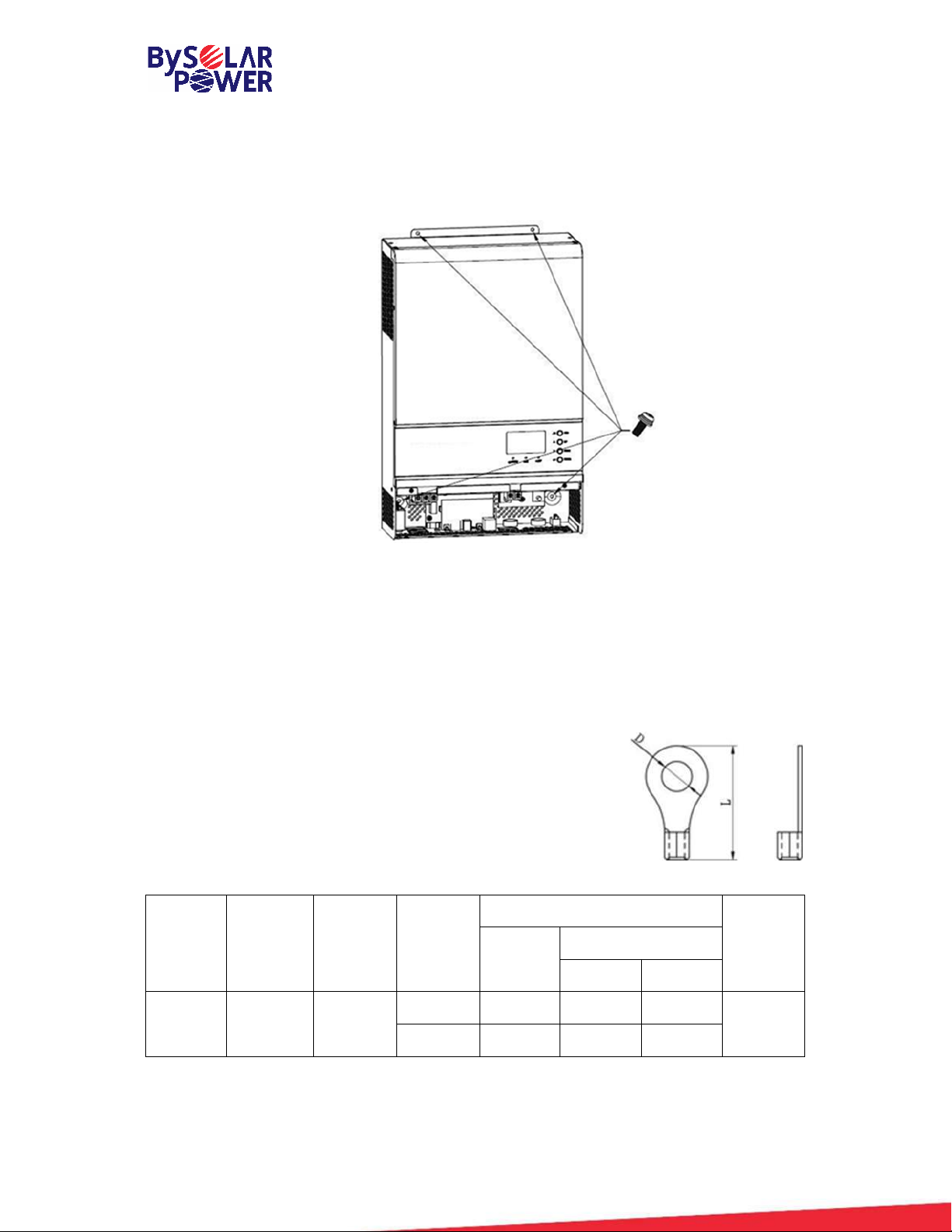
cable size. It’s very important to correctly operate this off grid solar inverter.
10. Please strictly follow installation procedure when you want to disconnect AC or DC terminals. Please refer
to INSTALLATION section of this manual for the details.
11. GROUNDING INSTRUCTIONS –This off grid solar inverter should be connected to a permanent grounded
wiring system. Be sure to comply with local requirements and regulation to install this inverter.
12. Fuses 1 pieces of 200A, 58VDC is provided as over-current protection for the battery supply.

ALENA ENERGY CO.,LTD
208, Nguyen Trai, 1 District, HCM City, Viet Nam
ĐT: (+84) 28.39.2626.83 / Fax: (+84) 28.39.2626.82 / Email: [email protected] / www.alena-energy.com
P a g e | 2
13. Warning!! Only qualified service persons are able to service this device. If errors still persist after
following troubleshooting table, please send this off grid solar inverter back to local dealer or service
center for maintenance.
Symbols
Symbol Explanation
Indicates a hazardous situation which, if not avoided, can result in machine
damage or people injury
Refer to page 23
Indicates a hazardous situation which, if not avoided, can result in machine
damage or people injury
Refer to page 24
Indicates overload which, if not avoided, can result in machine damage or people
injury
Refer to page 24

ALENA ENERGY CO.,LTD
208, Nguyen Trai, 1 District, HCM City, Viet Nam
ĐT: (+84) 28.39.2626.83 / Fax: (+84) 28.39.2626.82 / Email: [email protected] / www.alena-energy.com
P a g e | 3
Introduction.
Off-Grid Power System BSP 5S
BSP 5S is a smart-tech and multi-function inverter that can manage and control power usage in off grid type.
Developed using a powerful 32-bit microprocessor from Texas Instruments (USA) TMS320F2809. BSP 5S is
integrated with charger remote control module, MPPT 80A module, a high frequency pure sine wave inverter and
a UPS function module in one machine, which is perfect for off grid backup power and self-consumption applications.
The transformerless design provides reliable power conversion in compact size. The BSP uses advanced electronic
components to provide excellent power conversion with extremely compact dimensions.
The whole system also need other devices to achieve complete running such as PV modules, generator, or utility
grid. Please consult with your system integrator for other possible system architectures depending on your
requirements. The WiFi / GPRS module is a plug-.and-play monitoring device to be installed on the inverter. With
this device, users can monitor the status of the PV system from the mobile phone or from the website anytime
anywhere
BSP 5S is an ideal product for smart homes, islands and rural areas where shortage or insufficient national grid
occur. BSP 5S is proud to serve your home with green energy and ready to turn your house into a smart home.

ALENA ENERGY CO.,LTD
208, Nguyen Trai, 1 District, HCM City, Viet Nam
ĐT: (+84) 28.39.2626.83 / Fax: (+84) 28.39.2626.82 / Email: [email protected] / www.alena-energy.com
P a g e | 4
Features
Rated power 5KW, power factor 1
MPPT solar charge controller to maximize the solar output.
High frequency inverter with small size and light weight.
Pure sine wave AC output.
Overload, short circuit and deep discharge protection.
Configurable AC/ solar input priority via LCD setting.
Compatible to mains voltage or generator power.
WIFI/ GPRS remote monitoring
Parallel operation available.

ALENA ENERGY CO.,LTD
208, Nguyen Trai, 1 District, HCM City, Viet Nam
ĐT: (+84) 28.39.2626.83 / Fax: (+84) 28.39.2626.82 / Email: [email protected] / www.alena-energy.com
P a g e | 5
Product Overview
Single Model Parallel Model
6. AC input 7. WiFi/GPRS communication port
8. USB communication port 9. Dry contact
10. PV input 11. Power on/off switch
12. Battery input 13. Parallel communication ports (only for parallel)
14. Current sharing ports (only for parallel model) 15. AC output
16. Circuit breaker
NOTE: For parallel model installation and operation, please check separate parallel installation guide for the
details
LCD display
2. Status indicator
3. Charging indicator
4. Fault indicator
5. Function buttons

ALENA ENERGY CO.,LTD
208, Nguyen Trai, 1 District, HCM City, Viet Nam
ĐT: (+84) 28.39.2626.83 / Fax: (+84) 28.39.2626.82 / Email: [email protected] / www.alena-energy.com
P a g e | 6
Installation
Unpacking and Inspection
Before installation, please inspect the unit. Be sure that nothing inside the package is damaged. You should have
received the following items in the package:
The unit BSP 5S x 1
User manual x 1
Communication cable x 1
Preparation
Before connecting all wiring, please take off bottom cover by removing two screws as shown below.
Mounting the Unit
Consider the following points before selecting where to install:
Do not mount the inverter on flammable construction materials
Mount on a solid surface.
Install this inverter at eye level in order to allow the LCD
display to be read at all times.
The ambient temperature should be between 0°C and
55°C to ensure optimal operation.
The recommended installation position is to be adhered
to the wall vertically.
Be sure to keep other objects and surfaces as shown in
the right diagram to guarantee sufficient heat dissipation
and to have enough space for removing wires.
SUITABLE FOR MOUNTING ON CONCRETE OR
OTHER NON-COMBUSTIBLE SURFACE ONLY

ALENA ENERGY CO.,LTD
208, Nguyen Trai, 1 District, HCM City, Viet Nam
ĐT: (+84) 28.39.2626.83 / Fax: (+84) 28.39.2626.82 / Email: [email protected] / www.alena-energy.com
P a g e | 7
Install the unit by screwing three screws. It’s recommended to use M4 or M5 screws.
Battery Connection
CAUTION: For safety operation and regulation compliance, it’s requested to install a separate DC over-current
protector or disconnect device between battery and inverter. It may not be requested to have a disconnect device
in some applications, however, it’s still requested to have over-current protection installed. Please refer to typical
amperage in below table as required fuse or breaker size.
Ring terminal:
WARNING! All wiring must be performed by a qualified person.
WARNING! It's very important for system safety and efficient operation to use
appropriate cable for battery connection. To reduce risk of injury, please use the
proper recommended cable and terminal size as below:
Recommended battery cable and terminal size:
Model Maximum
Amperage
Battery
capacity Wire Size
Ring Terminal Torque
value
Momen
Cable
mm2
Dimensions
D(mm) L(mm)
5KVA 137A 200AH
1*2AWG 1*35 6.4 39.2
2~ 3 Nm
2*6AWG 2*16 6.4 33.2

ALENA ENERGY CO.,LTD
208, Nguyen Trai, 1 District, HCM City, Viet Nam
ĐT: (+84) 28.39.2626.83 / Fax: (+84) 28.39.2626.82 / Email: [email protected] / www.alena-energy.com
P a g e | 8
Please follow below steps to implement battery connection:
1. Assemble battery ring terminal based on recommended battery cable and terminal size.
2. Connect all battery packs as units requires. It’s suggested to connect at least 200Ah capacity battery
for 4KVA/5KVA model.
3. Insert the ring terminal of battery cable flatly into battery connector of inverter and make sure the bolts
are tightened with torque of 2-3 Nm. Make sure polarity at both the battery and the inverter/charge is
correctly connected and ring terminals are tightly screwed to the battery terminals.
WARNING: Shock Hazard
Installation must be performed with care due to high battery voltage in series.
CAUTION!! Do not place anything between the flat part of the inverter terminal and the ring
terminal. Otherwise, overheating may occur.
CAUTION!! Do not apply anti-oxidant substance on the terminals before terminals are connected
tightly.
CAUTION!! Before making the final DC connection or closing DC breaker/disconnector, be sure
positive (+) must be connected to positive (+) and negative (-) must be connected to negative (-).

ALENA ENERGY CO.,LTD
208, Nguyen Trai, 1 District, HCM City, Viet Nam
ĐT: (+84) 28.39.2626.83 / Fax: (+84) 28.39.2626.82 / Email: [email protected] / www.alena-energy.com
P a g e | 9
AC Input/Output Connection
CAUTION!! Before connecting to AC input power source, please install a separate AC breaker between inverter
and AC input power source. This will ensure the inverter can be securely disconnected during maintenance and fully
protected from over current of AC input. The recommended spec of AC breaker is 50A cho 5KVA.
CAUTION!! There are two terminal blocks with “IN” and “OUT” markings. Please do NOT mis-connect input and
output connectors.
WARNING! All wiring must be performed by a qualified personnel.
WARNING! It’s very important for system safety and efficient operation to use appropriate cable for AC input
connection. To reduce risk of injury, please use the proper recommended cable size as below.
Suggested cable requirement for AC wires.
Model Gauge (mm2) Torque Value
5KVA
10 1.4~ 1.6Nm
Please follow below steps to implement AC input/output connection:
1. Before making AC input/output connection, be sure to open DC protector or disconnector first.
2. Remove insulation sleeve 10mm for six conductors. And shorten phase L and neutral conductor N 3 mm.
3. Insert AC input wires according to polarities indicated on terminal block and tighten the terminal screws. Be
sure to connect PE protective conductor first.
→ Ground (yellow-green)
L → LINE (brown or black)
N → Neutral (blue)
WARNING:
Be sure that AC power source is disconnected before attempting to hardwire it to the unit.

ALENA ENERGY CO.,LTD
208, Nguyen Trai, 1 District, HCM City, Viet Nam
ĐT: (+84) 28.39.2626.83 / Fax: (+84) 28.39.2626.82 / Email: [email protected] / www.alena-energy.com
P a g e | 10
4. Then, insert AC output wires according to polarities indicated on terminal block and tighten terminal screws.
Be sure to connect PE protective conductor first.
→ Ground (yellow-green)
L → LINE (brown or black)
N→ → Neutral (blue)
5. Make sure the wires are securely connected.
CAUTION: Important
Be sure to connect AC wires with correct polarity. If L and N wires are connected reversely, it may cause utility
short-circuited when these inverters are worked in parallel operation.
CAUTION: Appliances such as air conditioner are required at least 2~3 minutes to restart because it’s required
to have enough time to balance refrigerant gas inside of circuits. If a power shortage occurs and recovers in a
short time, it will cause damage to your connected appliances. To prevent this kind of damage, please check with
manufacturer of air conditioner that if it’s equipped with time-delay function before installation. Otherwise, this off
grid solar inverter will trigger overload fault and cut off output to protect your appliance but sometimes it still
causes internal damage to the air conditioner

ALENA ENERGY CO.,LTD
208, Nguyen Trai, 1 District, HCM City, Viet Nam
ĐT: (+84) 28.39.2626.83 / Fax: (+84) 28.39.2626.82 / Email: [email protected] / www.alena-energy.com
P a g e | 11
PV Connection
CAUTION: Before connecting to PV modules, please install separately a DC circuit breaker between inverter and
PV modules.
WARNING! All wiring must be performed by a qualified personnel.
WARNING! It'’ very important for system safety and efficient operation to use appropriate cable for PV module
connection. To reduce risk of injury, please use the proper recommended cable size as below.
Model Typical Amperage Cable Size Torque
5KVA 80A 16mm2 1.4~1.6 Nm
PV Module Selection:
When selecting proper PV modules, please be sure to consider below parameters:
1. Open circuit Voltage (Voc) of PV modules not exceeds max. PV array open circuit voltage of inverter BSP 5S.
2. Open circuit Voltage (Voc) of PV modules should be higher than min. battery voltage.
Solar Charging Mode
INVERTER MODEL BSP 5S - 5KVA
Max. PV Array Open Circuit Voltage 145Vdc
PV Array MPPT Voltage Range 60~115Vdc
Min. battery voltage for PV charge 34Vdc
Please follow below steps to implement PV module connection:
1. Remove insulation sleeve 10 mm for positive and negative conductors.
2. Check correct polarity of connection cable from PV modules and PV input
connectors. Then, connect positive pole (+) of connection cable to positive
pole (+) of PV input connector. Connect negative pole (-) of connection
cable to negative pole (-) of PV input connector.
3. Make sure the wires are securely connected.

ALENA ENERGY CO.,LTD
208, Nguyen Trai, 1 District, HCM City, Viet Nam
ĐT: (+84) 28.39.2626.83 / Fax: (+84) 28.39.2626.82 / Email: [email protected] / www.alena-energy.com
P a g e | 12
Final Assembly
After connecting all wiring, please put bottom cover back by screwing two screws as shown below.

ALENA ENERGY CO.,LTD
208, Nguyen Trai, 1 District, HCM City, Viet Nam
ĐT: (+84) 28.39.2626.83 / Fax: (+84) 28.39.2626.82 / Email: [email protected] / www.alena-energy.com
P a g e | 13
Communication Connection
Please use supplied communication cable to connect to inverter and PC. Download the software from websize to
computer and follow on-screen instruction to install the monitoring software. For the detailed software operation,
please check user manual of from website www.alena-energy.com.
Dry Contact Signal
There is one dry contact (3A/250VAC) available on the rear panel. When program 24 is set as “disable”, it could
be used to deliver signal to external device when battery voltage reaches warning level. When program 24 is
set as “enable” and the unit is working in battery mode, it could be used to trigger the grounding box to
connect neutral and grounding of AC output together.
When program 24 is set as “disable” (default setting):
Unit Status Condition
Dry contact
port:
NC & C NO & C
Power Off Unit is off and no output is powered Close Open
Power On
Output is powered from Utility Close Open
Output is
powered from
Battery or
Solar
Program 01
set as Utility
Battery voltage < Low DC
warning voltage Open Close
Battery voltage > Setting value in
Program 13 or battery charging
reaches floating stage
Close Open
Program 01 is set
as SBU or Solar
first
Battery voltage < Setting value in
Program 12 Open Close
Battery voltage > Setting value in
Program 13 or battery charging
reaches floating stage
Close Open
When program 24 is set as “enable”:
Unit Status Condition
Dry contact
port:
NC & C NO & C
Power Off
Unit is off and no output is powered. Close
Open
Power On
Unit works in standby mode, line mode or fault mode Close
Open
Unit works in battery mode or power saving mode Open
Close

ALENA ENERGY CO.,LTD
208, Nguyen Trai, 1 District, HCM City, Viet Nam
ĐT: (+84) 28.39.2626.83 / Fax: (+84) 28.39.2626.82 / Email: [email protected] / www.alena-energy.com
P a g e | 14
Operation
Power ON/OFF
Once the unit has been properly installed and the batteries are connected well, simply press On/Off switch
(located on the button of the case) to turn on the unit.
Operation and Display Panel
The operation and display panel, shown in below chart, is on the front panel of the inverter. It includes
three indicators, four function keys and a LCD display, indicating the operating status and input/output
power information.
1. LCD display
2. Status indicator
3. Charging indicator
4. Fault indicator
5. Function buttons
LED Indicator
LED Indicator Messages
Green
Solid On Output is powered by utility in Line mode.
Flashing
Output is powered by battery or PV in
battery mode
Green
Solid On Battery is fully charged..
Flashing Battery is charging.
Red
Solid On Fault occurs in the inverter.
Flashing Warning condition occurs in the inverter..

ALENA ENERGY CO.,LTD
208, Nguyen Trai, 1 District, HCM City, Viet Nam
ĐT: (+84) 28.39.2626.83 / Fax: (+84) 28.39.2626.82 / Email: [email protected] / www.alena-energy.com
P a g e | 15
Function Buttons
Button Description
ESC To exit setting mode
UP
To go to previous selection
DOWN To go to next selection
ENTER To confirm the selection in setting mode or enter setting mode.

ALENA ENERGY CO.,LTD
208, Nguyen Trai, 1 District, HCM City, Viet Nam
ĐT: (+84) 28.39.2626.83 / Fax: (+84) 28.39.2626.82 / Email: [email protected] / www.alena-energy.com
P a g e | 16
LCD Display Icons
Icon Function Description
Input Source Information
Indicates the AC input.
Indicates the PV input
Indicate input voltage, input frequency, PV voltage, battery voltage and
charger current.
Configuration Program and Fault Information
Indicates the setting programs.
Indicates the warning and fault codes.
Warning: flashing with warning code.
Fault:lighting with fault code
Output Information
Indicate output voltage, output frequency, load percent, load in VA, load in
Watt and discharging current.
Battery Information
Indicates battery level by 0-24%, 25-49%, 50-74% and 75-100% in battery
mode and charging status in line mode.
These two signs indicate the charge priority
SOLAR indicates solar first.
UTILITY indicate utility first.
SOLAR blinking indicates solar onl;
SOLAR and UTILITY both on indicates combined charging.

ALENA ENERGY CO.,LTD
208, Nguyen Trai, 1 District, HCM City, Viet Nam
ĐT: (+84) 28.39.2626.83 / Fax: (+84) 28.39.2626.82 / Email: [email protected] / www.alena-energy.com
P a g e | 17
In AC mode, it will present battery charging status
Status Battery voltage LCD Display
Constant
Current mode / Constant
Voltage mode
<2V/cell 4 bars will flash in turns.
2 ~ 2.083V/cell Bottom bar will be on and the
other three bars will flash in turns
2.083 ~ 2.167V/cell
Bottom two bars will be on and
the other two bars will flash in
turns.
> 2.167 V/cell Bottom three bars will be on and
the top bar will flash.
Floating mode. Batteries are fully charged. 4 bars will be on.
In battery mode, it will present battery capacity.
Load Percentage Battery Voltage LCD Display
Load >50%
< 1.717V/cell
1.717V/cell ~ 1.8V/cell
1.8 ~ 1.883V/cell
> 1.883 V/cell
50%> Load > 20%
< 1.817V/cell
1.817V/cell ~ 1.9V/cell
1.9 ~ 1.983V/cell
> 1.983
Load < 20%
< 1.867V/cell
1.867V/cell ~ 1.95V/cell
1.95 ~ 2.033V/cell
> 2.033

ALENA ENERGY CO.,LTD
208, Nguyen Trai, 1 District, HCM City, Viet Nam
ĐT: (+84) 28.39.2626.83 / Fax: (+84) 28.39.2626.82 / Email: [email protected] / www.alena-energy.com
P a g e | 18
Load Information
Indicates overload.
Indicates the load level by 0-24%, 25-49%, 50-74% and 75-100%.
0%~24% 25%~49% 50%~74% 75%~100%
Mode Operation Information
Indicates unit connects to the mains.
Indicates unit connects to the PV panel.
Indicates load is supplied by utility power.
Indicates the utility charger circuit is working.
Indicates the DC/AC inverter circuit is working.
These three signs indicate the output priority.
SOL.FIRST indicates solar first.
BAT.FIRST indicates battery first.
UTI.FIRST indicates utility first.
Mute Operation
Indicates unit alarm is disabled.
Table of contents
Popular Inverter manuals by other brands

Goodwe
Goodwe GW5000-DNS-EU30 Quick installation guide

Nielsen
Nielsen CT4973 Original instruction

Goodwe
Goodwe ES Firmware Updating Guide

RedEarth
RedEarth HoneyBadger installation manual

EnerSys
EnerSys OutBack Power Radian International Series Operator's manual

Prudent Way
Prudent Way PWI-IV80-SB user manual

Mastervolt
Mastervolt WHISPER 9 user manual

Growatt
Growatt SPF 2000TL user manual

Mitsubishi Electric
Mitsubishi Electric FR-E5NC instruction manual

Kaco
Kaco blueplanet 3.0 NX3 M2 quick guide

Mitsubishi Electric
Mitsubishi Electric FR-A700 Series manual

Fuji Electric
Fuji Electric FRENIC 5000 G5 instruction manual