Alert-it S1026 User manual

UQ1133B Quick-start P154-P168 Radio (Sound).ppp Page 1of 3
V4.1
Quick-start guide for P154AA & AC Homecare Radio linked Bedside Monitor systems: Sound capable (S1026, S1029)
Install the sensing components Connect to P154 and test Normal Operation
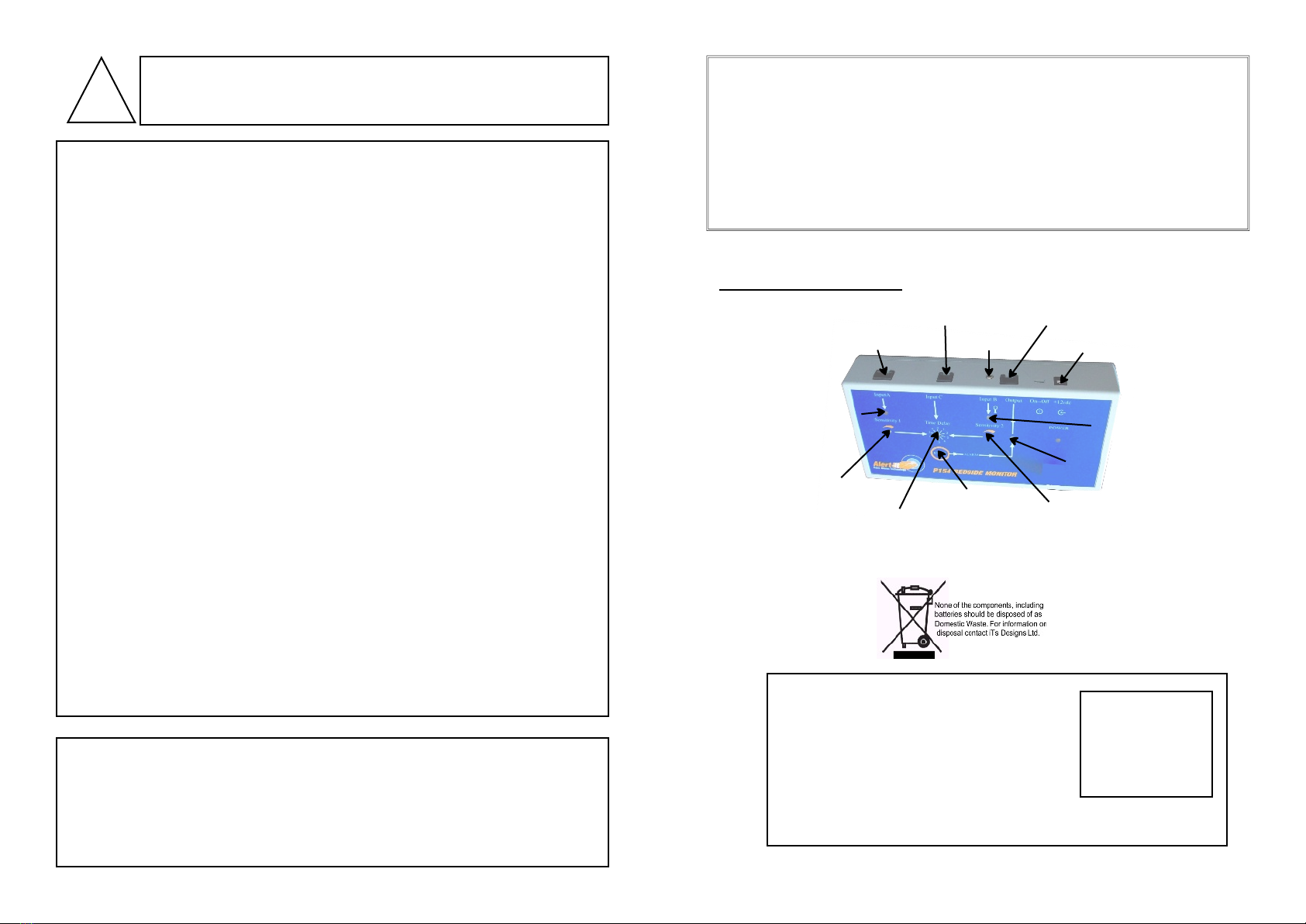
The system components and connection details are shown
overleaf. The actual range of sensors provided will depend on
your order requirements
Turn on the P154 by sliding the recessed switch on the rear
panel. The P154 has a internal battery which will charge
whenever the power supply is plugged in. If the battery
becomes discharged then a fault message will be
transmitted to the pager and the P154 will, on power-up or
pressing RESET, remain in a non-functional
state with all the lights flashing.
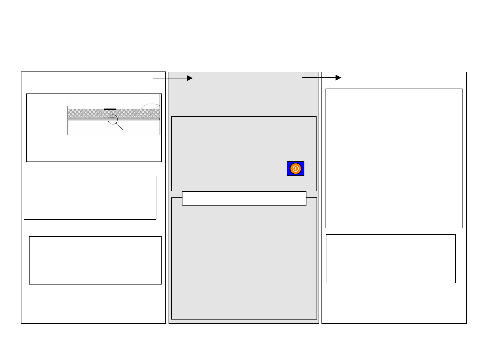
Turn on the Pager by pressing the ON/OFF
button for 3 seconds (in the event of no
response then charge the battery for at least 5 minutes)
Bed Occupancy reset has a special feature to
prevent false alarms during the day. If the RESET
button is pressed at any time with the occupant out
of bed, then the alarm detection is inhibited until the
mat is next operated, indicating that the client has
got into bed, and is therefore now to be monitored.
Once the test period has ended (indicated by the green
power light being mainly on with just a flicker every 8
seconds), the P154 will now detected alarms.
Remember that most sensors operate with a time delay
to reduce false alarms. When a sensor is stimulated the
corresponding light will illuminate and the time delay
starts. If the sensor activity stops then the light goes out
and the time delay is reset without sending an alarm. If
the sensor remains activated, the light will stay on and
the alarm will be transmitted after the delay, and the
ALARM light will illuminate.
The pager will now show the alarm light and will also
sound an appropriate audible alarm and vibrate (which
can be silenced for 5 minutes while attending the client
by pressing MUTE).
The alarm can be cleared at the pager by pressing the
button marked RESET on the P154 front panel, fol-
lowed by pressing the MUTE button on the pager if
required
For 30 seconds after turn-on or pressing RESET the unit is
in a test mode which allows you to confirm the various
sensors are working, without sending an alarm. This period
is indicated by the green power light flashing. Follow the
test sequence as appropriate:
Bed Movement. Tap the mattress and Input A light
should flicker with each tap. The amount of force needed
to make the light flicker can be adjusted
Bed Occupancy: If the system has such a provision then
Input B light will be on if no-one is sitting/lying on the mat.
Press the mat and ensure the light goes out.
Microphone. You will first need to sit on any Bed
Occupancy mat if fitted, to make Input B light extinguish.
The light should now flicker whenever a sharp sound or
click is made. The loudness of the sound to make the light
flicker can be adjusted (see setup sheet)
These tests must be repeated regularly to check the sensors
For S1028 install the Bed Occupancy Mat (B) on top of
the mattress under a suitable cover sheet, in a position that
ensures the maximum body weight is lying on the mat,
typically below the upper torso. Under the shoulder area is
a good place if an alarm is required before the users feet
touch the floor.
The optional microphone ( C) is plugged into the rear
socket and positioned near and convenient to the user.
There are two versions of the monitor. P154AA is sensitive
to repetitive sharp sounds (eg clicks and grunts or shouts),
the other (P154AC) has been designed to detect the sigh
that frequently preempts a seizure.
Install the Bed
Movement
Sensor (A)
underneath the
mattress on a
compliant bed
base or the
foam pad supplied., in a position below the rib cage. Its task
is to monitor the smallest bed movements transmitted
through the mattress.
C
A
B
The P154A is a flexible monitor capable supporting the care of those with Epilepsy by using a range of sensing elements and passing an alarm to a portable PlesioPager. This leaflet is a quick-
start guide to installing, testing and using your pre-configured system and it assumes the reader has skills comparable to operating a mobile phone. In addition they need to have sufficient
knowledge of the client to make the necessary risk assessment as to the suitability of the equipment to provide a safe environment. We are pleased to offer assistance including a full system
check via our telephone helpline, and would urge you to use this service. Should you wish to change any of the operating parameters or modify your system in any way, then detailed
handbooks, videos and risk assessment forms are available on request or on-line at www.alert-it.co.uk/support

UQ1133B Quick-start P154-P168 Radio (Sound).ppp Page 2of 3
V4.1
A small screwdriver to fit the controls is to be
found in the battery compartment on the
underside
Any adjustment to Bed Movement or Sound detection is made during the 30
second test period after switch on or RESET, when the effect can be observed
on the red indicators
Sensitivity Adjustment
The two sensitivity controls set the level at which the stimulus is detected. A
good starting place is the slot vertical (half-way) For maximum bed movement
sensitivity turn the control clockwise, with the small screw-driver supplied ,
but not so far that the red indicator is permanently on or flashing. Turn anti-
clockwise to reduce over-sensitivity while ensuring the red indicator flashes
each time a stimulus at the anticipated level is made.
Bed Vacation Time Setting (S1029)
The default setting is 6 minutes, which is used to detect the user collapsing out of
bed, while allowing the user freedom for visiting the bathroom for instance. This
can be changed in the range 5 seconds to 21 minutes, but requires removal of the
P154 base and a reset procedure using the links exposed. For this please refer to the
UH1102B P154 Installers Handbook
P154 Sensor Adjustment
System components and connection
(actual components supplied may vary to order)
Part Description Part No
A Bed Movement Sensor P114A
B Bed Occupancy Mat P143C
C Microphone P158A
D Bedside Monitor P154*
E Power Supply for A P171*
F Pager P168A
G Power Supply for F P153*
H Nurse Call/Annunciator Lead (optional) P145*
I Mounting bracket P159A
Alarm Indications
P154 Indication Pager Alarm Meaning
None Red On
Radio signal lost from the node
Red light A on
steady
Alarm On
Red Flash
Client is in distress (Bed Movement
Alarm)
Red light B on
steady
Alarm On
Red Flash
Client is in distress (Sound Alarm)
Red light B flash-
ing
Alarm On
Red Flash
Client is in distress (Bed Vacation
Alarm)
Red light A flash-
ing
Alarm On
Red Flash
Client is in distress (Additional senor
eg Floor Mat)
On power-up or
RESET all LED’s
will flash as warn-
ing
Red Flash Battery is client’s system needs charg-
ing
Alarm reset at moni-
tor
Alarm On
Red Off
Press MUTE to silence & reset pager
Items F, G are part of S1026, S1029 only
A
B
C
D
E
G
H
I
F
Full adjustment details are found in
handbooks available on:
www.alert-it.co.uk/handbooks/
Or by phoning Alert-iT
Time Delay Adjustment
The delay is a time for which the distress condition
(sound or movement) must occur before the alarm is
sent and is set by altering the position of small rotary
switch according the table. The period should be set
to minimize false alarms during normal movement.
As delivered the sensitivity should be suitable for
detecting spasms in a domestic bed and the time
delay of 15 seconds (position 3) will normally be a
good compromise between speed of detection and
avoiding false alarms during nocturnal restlessness or
short, self-healing spasms. Please refer to the
TESTING procedure for confirming acceptable
operation.
The sound detection is time is set according to the
movement time delay, and is different for the two
models
Sound detection I suspended if Bed Vacation is
detected following RESET
P154BA Sound Bursts
Bed
Movement
Transient
Sound
Time
(sec)
Rate
(sec)
Ti
me
Rate
(Sec)
0
2.5
1.5
2.5
1.5
1
5.5
1.5
5.5
1.5
2
10
2
7
1.5
3
15
2
7
2
4
20
3
10
3
5
25
3
10
3
6
30
3
10
3
7
40
3
10
3
8
50
3
10
3
9
60
3
10
3
P154BC Sigh
Bed
Movement
Sigh-
Sound
Time
(sec)
Rate
(sec)
Time
(Sec)
0
10
2
1.5
1
15
2
1.5
2
10
2
2
3
15
3
2
4
20
2
2
5
25
2
2
6
10
3
2.5
7
15
2
2.5
8
20
2
3
9
25
3
3

UQ1133B Quick-start P154-P168 Radio (Sound).ppp Page 3of 3
V4.1
This symbol indicates there are warnings and precautions associated with the
use of this equipment. This instruction manual should be carefully read and un-
derstood before using the equipment.
!
Support
For technical support please fax or EMail:
HELP: 0845 2179951
FAX : 0845 2179953
...using technology to care for carers
Designed by:
ITs Designs Ltd
Leicester
LE9 9FE UK
The Alert-it system has been designed with due regard to reliability and integrity.
While it offers a highly vigilant monitoring method,it is always possible that a
distress condition can go undetected for a variety of reasons (including malfunction)
and in life threatening situations it is advisable to use the Alert-it system in
conjunction with additional monitoring techniques (e.g. video). Neither the
manufacturer nor its agent can accept legal responsibility to provide a system that is
infallible. The carer is responsible for assessing the risks of using this equipment and
any settings pertaining to it.
The system complies with 93/42/EEC as a Class 1 Medical Device for use in a Home Health-
care environment
The system complies with EN60601 for Class 2 Electrical Safety and does not need a protec-
tive earth.
The system has a radio transmitted compliant to EN300-220 operating at 434.075MHz wide-
band 10mW power (class 8) less than 1% duty cycle (class 2)
1. Ensure the voltage & current rating of remote signalling equipment (Nurse Call etc) does
not exceed the maximum allowed (50v/100mA)
2. Ensure that the senor cable is routed and secured to avoid the risk of entanglement or
strangulation.
3. Only the recommended power supply shall be used as it is certified to provide two means
of patient protection to EN60601-1
4. Ensure the power cable is routed to avoid a trip hazard
5. Regularly check the power supplies for damage and potential shock risks
6. Clean and disinfect each item regularly in accordance with information on page 7
7. Ensure, by testing, that the alarm is annunciated at the carer's location(s)
8. Regularly sensors test as defined herein
9. Use only the power supply and batteries recommended
10. Operate power supply and charge pager away from direct heat and uncovered.
11. As with all medical electronic equipment there is potential for the equipment to interfere
with or be effected by interference from other electrical or electronic devices. For this rea-
son avoid placing the monitor, sensor or connecting cable in close proximity to sensitive
electronic devices or devices which produce strong electromagnetic fields such as radio
transmitters, mobile phones or power cables.
12. Only use the monitor with accessories approved for use with this product and only in ac-
cordance with instructions.
13. If the equipment is modified in any way, appropriate inspection and testing must be con-
ducted to ensure continued safe use of the equipment.
14. The carer must conduct a risk assessment to determine if the level of reliability offered by
the monitor is sufficient or if additional monitoring is needed. Contact the manufacture
for assistance with Risk Evaluation Tools.
15. Additional levels of mechanical protection may be needed for some patient disorders.
Contact the manufacturers for advice
16. Some accessories are fitted with small screws and have plastic bags. Ensure these do not
come into the possession of vulnerable patients who might choke on them
17. Any sensor over the mattress (Bed Vacation or Incontinence) has the potential to cause
pressure sores . The carer must assess this risk and monitor the use of these products
18. Any sensor over the mattress could pose a fire hazard if in contact with a smouldering
cigarette.
Bed Movement
Nurse Call
Microphone
Bed Vacation
Power
Bed Movement
Sensitivity
Sound Sensitivity
Time Delay
Alarm Reset
Bed Vacation
& Sound Light
Bed Movement
Light
Alarm
Control and Indicators
This manual suits for next models
1
Other Alert-it Microphone manuals