4 Installation
Read the instructions carefully and pay special attention to the warnings!
Always check the tank cleaning machine before operation.
Step 4
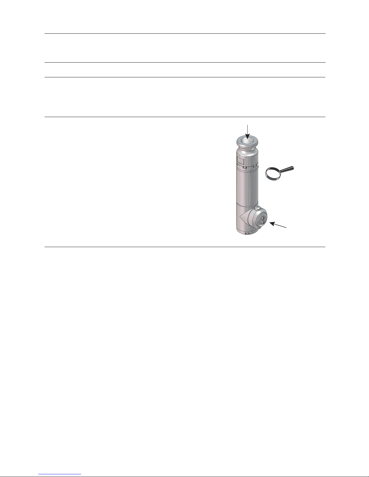
Mounting
Before mounting the Alfa Laval GJ 9, make sure the supply line
has been adequately flushed. It can be mounted on a rigid 3/4"
pipe using a pipe wrench. For most applications, the Alfa Laval GJ
9 will be mounted with the inlet connection pointing up; however,
the Alfa Laval GJ 9 will function at any orientation.
The Alfa Laval GJ 9 can be suspended from the top of the tank
viaaflexiblehose.Thedualnozzlemachineisdesignedtohave
balanced forces in order to keep it centred, even while hanging.
We do not, however, recommend attaching the machine to a
flexible hose while in the inverted or horizontal orientation. This
form of mounting is not stable and, thus, will not maintain the Alfa
Laval GJ 9’s position in the tank.
WARNING
When attaching the Alfa Laval GJ 9 onto the supply pipe, ALWAYS
apply the wrench to the inlet collar (41) at the top/inlet of the unit.
Never use a wrench on stem (1), tee housing (3) or tee housing
base (9) to tighten the unit onto the pipe. Doing so risks internally
damaging the machine. Refer to step 1 in chapter 6.1 General
maintenance .
9
3
1
41
4119-0004
!
Step 5
Location inside tank
Generally, a single Alfa Laval GJ 9 will be positioned in the approximate centre of the vessel in order to equalise the cleaning
radius in all directions.
Some vessels, however, may have specific cleaning problems such as coils or heavy deposits such as the liquid level line
(bathtub ring). In these situations, it is recommended that the Alfa Laval GJ 9 is located closer to the difficult area for the
best cleaning results.
Tanks with internal mechanisms or structures such as an agitator shaft, impellers or baffles will require careful positioning to
minimise the "shadow" on areas which do not receive direct jet impact. Sometimes, more than one machine, or, more than one
placement of a single machine, may be necessary to avoid shadow problems or "striping."
Step 6
Entry openings
When using the Alfa Laval GJ 9, the vessels being cleaned must provide entry openings large enough to avoid interference
during insertion and removal. The minimum opening size required for the Alfa Laval GJ 9 is 71.1 mm diameter (2.80 inches) for
free-hand installation and 96.0 mm (3.78") for automated (fixed-centreline) installation.
Step 7
Vessel drainage
If it is necessary to clean the floor of a vessel, remember that standing liquid will diminish the effectiveness of the Alfa Laval GJ
9 by covering any soils underneath. Wherever possible, the tank floor should be pitched toward the drain and the drainage
opening should be large enough to eliminate or reduce any liquid buildup or puddling. If gravity alone is insufficient, a scavenger
or stripper pump should be connected to the drain to suck out the excess wash fluid. In extreme cases, it may be necessary to
use smaller nozzles on the Alfa Laval GJ 9 or even to operate it intermittently to allow time for draining.
Step 8
Filters and strainers
All tank cleaning systems should be equipped with a filter or strainer that will trap solids 0.006" (150 micron, 100 mesh) or
larger, as these will not pass through the Alfa Laval GJ 9. These particles can become caught in one of the internal passages of
the machine and cause it to stop turning or reduce its cleaning effectiveness due to a loss of flow. It will then be necessary to
disassemble the Alfa Laval GJ 9 and remove the blockage.
In recirculated (closed-loop) cleaning or any other application where the cleaning solution may carry abrasive solids in
suspension, adequate filtration is a must. These particles can be extremely destructive to the Alfa Laval GJ 9, pumps, valves,
and other system components. Filters, properly installed and maintained, will more than pay for themselves with lower overall
operating costs for these applications. Furthermore, to ensure that clogged filters or strainers are cleaned, we recommend
using automatic self-cleaning models.
10