Alfalaval SaniMega User manual

4005-0010
Covering:
Standard Machines
TE91A590-EN6
First published: January 1, 1988
ESE01793-EN6 2016-02
Original manual
Instruction Manual
Alfa Laval Toftejorg™ SaniMega


Table of contents
The information herein is correct at the time of issue but may be subject to change without prior notice
1. EC Declaration of Conformity ....................................................................... 4
2. Safety .................................................................................................... 5
2.1. Important information ............................................................................. 5
2.2. Warning signs ..................................................................................... 5
3. Introduction ............................................................................................ 6
3.1. Introduction ........................................................................................ 6
3.2. Intended Use ...................................................................................... 7
3.3. Patents and Trademarks ......................................................................... 7
3.4. Quality System .................................................................................... 7
4. Installation .............................................................................................. 8
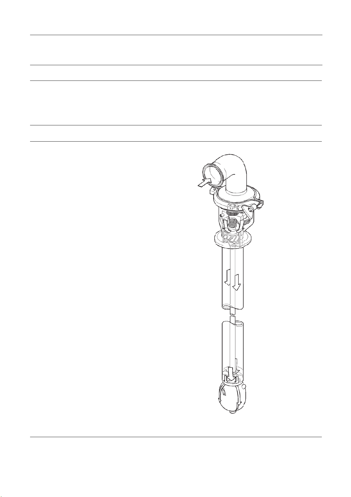
4.1. General Description ............................................................................... 8
4.2. Functioning ........................................................................................ 8
4.3. General Safety and Installation Instructions .................................................... 9
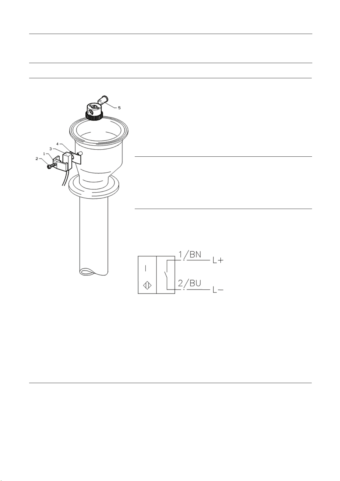
4.4. Rotacheck add-on Installation Guide ........................................................... 10
5. Operation ............................................................................................... 11
5.1. Normal operation ................................................................................. 11
6. Maintenance and Repair ............................................................................. 12
6.1. Preventive Maintenance .......................................................................... 12
6.2. Turbine and Gear Assembly ..................................................................... 13
6.3. Cleaner Head Assembly ......................................................................... 14
7. Technical Data ......................................................................................... 15
8. Parts Lists and Drawings ............................................................................ 18
8.1. Parts list, Alfa Laval Toftejorg SaniMega ........................................................ 18
8.2. Parts drawings, Alfa Laval Toftejorg SaniMega ................................................ 19
8.3. Parts list and drawing, Alfa Laval Rotacheck .................................................. 20
9. Standard Spare Part and Service Kits ............................................................. 21
10. General information ................................................................................... 22
10.1.Service & Repair .................................................................................. 22
10.2.How to order Spare Parts ........................................................................ 22
10.3.How to contact Alfa Laval Tank Equipment .................................................... 22
11. Declaration of compliance for food contact materials .......................................... 23
3

1 EC Declaration of Conformity
The Designated Company
Alfa Laval Kolding A/S
Company Name
Albuen 31, DK-6000 Kolding, Denmark
Address
+4579322200
Phone No.
hereby declare that
Tank Cleaning Machine
Designation
Alfa Laval Toftejorg SaniMega
Ty p e
From serial number 2016-0001 to 2030-99999
is in conformity with the following directive with amendments:
Machinery Directive 2006/42/EC
- DS/EN ISO 12100:2010
The Pressure Directive 97/23/EC
- According to its own volume and the rated pressure range, the product is regarded an Article 3, paragraph 3 Equipment
FDA 21CFR§177
Regulation (EC) 1935/2004
The person authorised to compile the technical file is the signer of this document
Global Product Quality Manager
Pumps, Valves, Fittings and Tank Equipment Lars Kruse Andersen
Title Name
Kolding 2016-02-01
Place Date Signature
(This Declaration of Conformity replaces Declaration of Conformity dated 20156-01-01)
4

2 Safety
Unsafe practices and other important information are emphasized in this manual.
Warnings are emphasized by means of special signs.
Always read the manual before using the tank cleaning machine!
2.1 Important information
WARNING
Indicates that special procedures must be followed to avoid serious personal injury.
CAUTION
Indicates that special procedures must be followed to avoid damage to the tank cleaning machine
NOTE
Indicates important information to simplify or clarify procedures.
2.2 Warning signs
General warning:
5

3 Introduction
3.1 Introduction
This manual has been prepared as a guide for installing, operating and maintaining your Alfa Laval Toftejorg Rotary Spray Head
tank cleaning machine. Should you require further assistance, our Technical Sales Support department and worldwide net
of sales offices will be pleased to help you. Please quote the type, article and serial numbers with all of your enquiries;
this helps us to help you.
Important
information:
Before installing the machine and setting it into operation, carefully read the General Safety and Installation
Instructions (page 9) and take all necessary precautions according to your application and local regulations.
NOTE
The illustrations and specifications contained in this manual were effective at the date of printing. However, as continuous
improvements are our policy, we reserve the right to alter or modify any unit specification on any product without prior notice or
any obligation.
The English version of the instruction manual is the original manual. We make reservations in regard to possible mistranslations in
language versions of the instruction manual. In case of doubt, the English version of the instruction manual applies.
© Alfa Laval Corporate AB
This document and its contents is owned by Alfa Laval Corporate AB and protected by laws governing intellectual property and
thereto related rights. It is the responsibility of the user of this document to comply with all applicable intellectual property laws.
Without limiting any rights related to this document, no part of this document may be copied, reproduced or transmitted in
any form or by any means (electronic, mechanical, photocopying, recording, or otherwise), or for any purpose, without the
expressed permission of Alfa Laval Corporate AB. Alfa Laval Corporate AB will enforce its rights related to this document to the
fullest extent of the law, including the seeking of criminal prosecution.
The serial number is placed on the Gear house of the tank cleaning machine.
Serial number
4005-0009
6

3 Introduction
3.2 Intended Use
End-user should verify:
- that the tank cleaning machine is in conformity with respect to tank, vessel or container size in which it is used.
- that the construction materials (both metallic and non-metallic) are compatibility with product, flushing media, cleaning
media, temperatures and pressure under the intended use.
See General Installation Instructions on page 9 of this manual for information on recommended installation position.
3.3 Patents and Trademarks
This Instruction Manual is published by Alfa Laval Kolding A/S without any warranty. Improvements and changes to this
Instruction Manual may at any time be made by Alfa Laval Kolding A/S without prior notice. Such changes will, however,
be incorporated in new editions of this Instruction Manual.
Alfa Laval Kolding A/S. All rights reserved.
The Alfa Laval logotype is a trademark or a registered trademark of Alfa Laval Corporate AB. "Toftejorg™" is a trademark or
registered trademark of Alfa Laval Kolding A/S. Other products or company names mentioned herein may be the trademarks
of their respective owners. Any rights not expressly granted herein are reserved.
3.4 Quality System
The Alfa Laval Toftejorg Rotary Spray Head is produced according to Alfa Laval Kolding´s ISO 9001 international Standard
certified quality system.
7

4 Installation
4.1 General Description
The Alfa Laval Toftejorg SaniMega is a media driven and media lubricated tank cleaning machine, which is being used at fixed
vertical installations. The Alfa Laval Toftejorg SaniMega rotary spray head provides a controlled rotating fan impact cleaning
action. It is an automatic device with an optimised design for distribution of cleaning fluids in vertical cylindrical tanks. However,
it can also be used for a number of other tank shapes and vessels.
4.2 Functioning
The cleaning media is lead through the inlet connection
and into the housing, where it flows through the Gear
and the Turbine, setting the Turbine into rotation. It then
continues downwards to the Cleaner head and out
through the slots.
The rotation of the Turbine is via the Gear transmitted to
the Drive shaft, which makes the Cleaner head rotate at
a steady speed. The resulting fans of the cleaning media
cleans the targeted surfaces by impact and provides a
swirling action down the tank wall.
The Alfa Laval Toftejorg SaniMega contains no lubricating
substances such as oil or grease. All materials are
selected for contact with foods, and the machine is
self-cleaning, i.e. all internal and external surfaces within
the product contact area are cleaned.
The Alfa Laval Toftejorg SaniMega can, as an option, be
fitted with a non-invasive electronic Rotation Sensor to
verify the rotation of the cleaner.
41050008_1.eps
8

4 Installation
4.3 General Safety and Installation Instructions
The Alfa Laval Toftejorg SaniMega is designed for fixed vertical installation in vertical tanks. It is recommended to install a filter
in the supply line in order to avoid particles larger than 2.5 mm like scale etc. from clogging the inside of the cleaner. Fine
solid particles in the cleaning fluid will result in increase of wear and may cause slower rotation speed or stoppage.
Before installation, all supply lines and valves must be flushed to remove remains of welding electrodes, grinding dust, scale
and other foreign matter.
Note: The machine shall be installed in accordance with national regulations for safety and other relevant regulations
and standards. Precautions shall be made to prevent starting the cleaning operation, while personnel are inside the tank
or otherwise can be hit by jets from the cleaner head. In EU-countries the complete system must fulfil the EU-machine
directive and shall be CE-marked.
Warning: The machine is not designed for installation in tanks with a potential explosive atmosphere, where build-up of
static electricity on the cleaner head can result in risk of sparks and consequently an explosion may follow.
9

4 Installation
4.4 Rotacheck add-on Installation Guide
The Rotacheck Sensor is a Namur-type magnetic sensor according to DIN
19234. The sensor must be supplied from an external relay.
When the Magnet inside the cleaner passes the sensor, an impulse is sent
to the relay.
Technical Data:
Dimensions: 12x12x30 mm
Connection, electrical: 2 m, PVC-cable
2 x 0.34 mm2
Supply voltage: 5-24 V DC
Supply voltage, ex. approv.: Max. 8.2 V DC
Current consumption, magnet sensed: 3mA
Current consumption, not sensed: 1mA
Operating temperature: -25°C to 70°C
Material of Housing: PBT
Enclosure: IP67
Ex-class: EEx ia II T6
Standard Symbol:
TD523543
TD523544
Working Instructions:
(Ref. page 19 for positions)
1. Remove the Inlet connection (Pos. 19, page 19)
2. Remove Circlip (Pos. 11) and Gear wheel (Pos. 4, page 19)
3. Fit Magnet (Pos. 5) in Gear wheel
4. Fit Gear wheel with Magnet complete on shaft
5. Fit Inlet connection
6. Fit pos. 1, 2, 3 and 4 on the Housing. Position of the Sensor is important. It must be fitted on the right side of tap.
10

5Operation
5.1 Normal operation
Cleaning Media
Use only media compatible with Stainless Steel AISI 316L, PTFE, PEEK and EPDM. Please note that PEEK is not resistant to
concentrated sulfuric acid. Normal detergents, moderate solutions of acids and alkalics are acceptable. Aggressive chemicals,
excessive concentrations of chemicals at elevated temperatures, as well as certain hypochlorids should be avoided. If in
doubt, contact your local Alfa Laval sales office.
Temperature
Max. temperature 140°C at steam sterilisation.
Pressure
Please make sure that the connections are correctly mounted before opening of the washing valve. Put on pressure gradually
in order to avoid hydraulic shocks, which might stress mechanical parts in the Alfa Laval Toftejorg SaniMega cleaner. Max.
pressure is 4.0 bar.
After-use cleaning
After using the Alfa Laval Toftejorg SaniMega, flush the machine with clean water. Cleaning solutions should never be allowed to
dry or set-up in the system due to possible "salting out" or "scaling" of the cleaning ingredient.
Warning: Do not touch hot surfaces when working with hot cleaning solutions or steaming.
Never try to loosen clamps without securing against pressure on the pipe line.
11

6 Maintenance and Repair
6.1 Preventive Maintenance
In order to keep your tank cleaning machine servicing you as an efficient tool in your tank cleaning operations, it is essential
that you maintain its high performance. A simple preventive maintenance programme will keep your tank cleaning machine
in good condition.
Good maintenance is careful and regular attention!
The following recommended preventive maintenance is based on tank cleaning machines working in average conditions. A
tank cleaning machine, which has a rough and dirty job to do, needs more frequent attention than one working under ideal
conditions. We trust that you will adjust your maintenance programme accordingly.
Always use only proper tools. Unless otherwise stated never use unnecessary force (i.e. hammer or pry) to put components
together or take them apart. Always perform all assembly/disassembly steps in the order described in this manual.
Never assemble components without previous cleaning. This is especially important at all mating surfaces. Work in a
clear well lighted work area.
Every 300-500 working hours
(Ref. page 13for positions)
Inspect the gear, turbine parts and bearings:
Disassembly
1. Dismount the Clamp ring, inlet connection and Gasket (Pos. 20, 19 and 21).
2. Remove Circlip (Pos. 11) and remove Gear wheel (Pos. 4). Push out Cylindrical Pin (Pos. 3). Be careful not to drop Pin
into machine.
3. Remove the Gear assembly from the Drive shaft (Pos. 9). The Turbine shaft (Pos. 8) is now released and can be removed.
Check/Inspection
1. Check the Worm and Worm wheel on the Horizontal shaft (Pos. 12). Replace shaft if teeth are worn more than 50%.
2. Check that the Horizontal shaft (Pos. 12) and the Worm wheel (Pos. 2) can be rotated freely without any uneven resistance.
Check Turbine bearings (Pos. 6). Replace Bearings if hole is worn to more than ø10.3 mm.
3. Replace if Collar on lower Bearing has been worn to 1.0 mm or less.
Reassembly
1. Reassembly is carried out in the opposite order.
12

6 Maintenance and Repair
6.2 Turbine and Gear Assembly
Disassembly:
1. Remove Circlip (pos. 11) and remove the Gear wheel (Pos. 4) . Push out Cylindrical Pin (Pos. 3)
2. Remove the Gear assembly from the Drive Shaft (Pos. 9). The Turbine shaft (Pos. 8) is now released and can be removed.
3. Remove Circlip (Pos. 11) and pull out the Pinion (Pos. 1) releasing the Worm wheel (pos. 2) and Washer (Pos. 14).
4. Remove the Circlip (Pos. 11) and the Horizontal shaft (Pos. 12).
Reassembly:
1. Reassembly is carried out in the opposite order.
Before mounting Gear wheel (Pos. 4) make sure that the Horizontal shaft (Pos. 12) and the Worm wheel (Pos. 2) can be
rotated easily without any uneven resistance.
TD523546
13

6 Maintenance and Repair
6.3 Cleaner Head Assembly
Disassembly:
It is necessary to disconnect the cleaner from any piping etc. and dismount it from the tank. Place the machine on a level surface.
1. Dismount the Clamp ring, Inlet connection and Gasket (Pos. 20, 19 and 21, see page 13).
2. Push the Cleaner head up (Pos. 17) and remove the Lock ring (Pos. 18). If necessary hold Drive shaft (Pos. 9) in position
when pushing the Cleaner head up.
3. Pull off Cleaner head.
Reassembly:
Reassembly is carried out in the opposite order.
TD523545
14

7 Technical Data
Weight of machine: 6.0 kgs (13.3 lbs)
Working pressure: 2-4 bar (28-58 psi)
Recommended inlet pressure: 3bar(44psi)
Max. working temperature: 95°C (203°F)
Max. sterilisation temperature: 140°C (284°F)
Max. ambient temperature: 140°C (284°F)
Effective cleaning radius: 3m(10ft.)
Standard connection: Inlet: 2” ISO clamp. Tank: 3” ISO clamp
Standard downpipe length: 1.200 or 1.500 mm
Min. tank opening: ø72.5 mm
Materials: Stainless steel AISI 316L, PTFE, PEEK, EPDM
Options
-A non-invasive electronic Rotation Sensor to validate speed of the cleaner
-Downpipe length 800 or 1.000 mm
-Inlet connection as welding end 2” ISO (ø51x1.2)
-Tank inlet as DIN Union NW100
-Counter parts to the standard clamp connections including gaskets and clamp rings
TD523535 TD523536 TD523537
Rotation Sensor Inlet connection as welding end Tank inlet as DIN Union
15

7 Technical Data
Principal dimensions (mm)
116
144
TD523540
120.5*
220**
TD523541
86.5* 2” ISO Clamp
3” ISO Clamp
1200 / 1500
1505 / 1805
53
ø65
72
Dimensions for Options:
* For Welding end: 65/99 mm
** For NW100 DIN Union: 234 mm
16

7 Technical Data
Performance Data
Flow
rate
Throw
length
Inlet pressure Inlet pressure
17

8 Parts Lists and Drawings
8.1 Parts list, Alfa Laval Toftejorg SaniMega
Pos. Ref. No. No./Unit Description Material
1TE12A514 1Pinion Polymer
2 TE12A508 1Worm wheel Stainless steel
3TE51C017 1Cylindrical Pin Stainless steel
4TE12A506 1Gear wheel Stainless steel
5TE12A528 2 Bush Polymer
6TE20G640 3 Bearing for Turbine shaft Polymer
7TE12A505 1Gear frame Stainless steel
8 TE12A509 1Turbine sh af t Stainless steel
9TE12A530/33 1Drive Shaft Stainless steel
10 TE12A507 1Shaft Stainless steel
11 TE51C202 3Circlip Stainless steel
12 TE12A513 1 Horizontal shaft Polymer
13 TE51C004 1Pin Stainless steel
14 TE12A515 1Washer Polymer
15 TE12A566 1Washer Stainless steel
16 1Housing *Note
17 TE12A573 1 Cleaner head Stainless steel
18 TE12A559 1 Lock ring Stainless steel
19 TE12A526 1Inlet connection Stainless steel
20 TE51S128 1Clamp ring Stainless steel
21 TE51S118 1Gasket Elastomer
*Note: Pos. 16 is not sold as single spare part component but only as part of a machine maintenance/repair order. For further
information please contact Alfa Laval Customer Support.
18

8 Parts Lists and Drawings
8.2 Parts drawings, Alfa Laval Toftejorg SaniMega
TD523546
TD523545
19

8 Parts Lists and Drawings
8.3 Parts list and drawing, Alfa Laval Rotacheck
Rotacheck for Alfa Laval Toftejorg SaniMega complete TE12A305
Pos. Ref. No. No./Unit Description Material
1 TE12A555 1 Clamp for sensor Stainless steel
2 TE51A148 1 Screw Stainless steel
3 TE51V555 1Sensor
4TE12A557 1Isolator for sensor Polymer
5TE12A356 1Magnet complete
TD523543
20
Table of contents
Other Alfalaval Plumbing Product manuals
Popular Plumbing Product manuals by other brands

baliv
baliv DU-5040 Series manual

Brizo
Brizo 62710LF Installation

Robern
Robern CRAFT CB-TA36MCO102-8CS8 installation instructions

Moen
Moen EASY CLEAN XLT 6303 Specifications

DXV
DXV Keefe D35104.430 installation instructions

Hans Grohe
Hans Grohe AXOR Starck 10101 1 Series Installation/User Instructions/Warranty

IKEA
IKEA BROGRUND quick start guide

Intra
Intra INT 01NK Instructions for use

Quooker
Quooker PRO3 installation guide

Lefroy Brooks
Lefroy Brooks M2-4300 Installation, operating, & maintenance instructions

Sanipex
Sanipex BAGNODESIGN BDM-TOK-309-A Series installation guide

Stand Aid of Iowa
Stand Aid of Iowa PTA Instructions and warranty