Alfalaval 8692 User manual

Quickstart
English Deutsch Français
Type 8692 / 8693
Positioner / Process Controller
Positioner / Prozessregler
Positionneur / Régulateur de process
ESE02210EN/DE/FR

We reserve the right to make technical changes without notice.
Technische Änderungen vorbehalten.
Sous réserve de modifications techniques.
© 2011 - 2012 Alfa Laval A/S
Quickstart 1202/01_EU-ML_00809647 / Original DE

3
Type 8692, 8693
1. QUICKSTART .....................................................................................................5
1.1. Symbols .............................................................................................. 5
2. AUTHORIZED USE .........................................................................................6
2.1. Restrictions ........................................................................................ 6
2.2. Predictable misuse ..........................................................................6
3. BASIC SAFETY INSTRUCTIONS .............................................................7
4. GENERAL INFORMATION ...........................................................................8
4.1. Contact address ...............................................................................8
4.2. Warranty ............................................................................................. 8
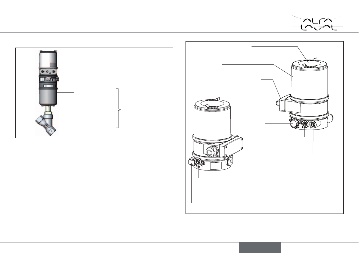
5. DESCRIPTION OF SYSTEM .......................................................................9
5.1. Functions ..........................................................................................10
6. TECHNICAL DATA ........................................................................................10
6.1. Conformity .......................................................................................10
6.2. Standards .........................................................................................10
6.3. Operating conditions .....................................................................10
6.4. Mechanical data .............................................................................11
6.5. Type label ........................................................................................11
6.6. Pneumatic data ...............................................................................11
6.7. Electrical data..................................................................................12
7. CONTROL AND DISPLAY ELEMENTS ...............................................13
7.1. Function of the keys ........................................................................ 13
7.2. Operating state ................................................................................ 14
7.3. Operating levels ............................................................................... 14
7.4. Display in operating state AUTOMATIC .................................... 15
8. INSTALLATION ...............................................................................................15
8.1. Safety instructions .........................................................................15
8.2. Installing the positioner / process controller
on process valves belonging to series 2103 and 23xx .........16
8.3. Installing the positioner / process controller
on process valves belonging to series 26xx and 27xx ............. 17
9. FLUID INSTALLATION ................................................................................19
9.1. Safety instructions .........................................................................19
9.2. Installing the process valve ..........................................................19
9.3. Pneumatic connection of the positioner /
process controller ..........................................................................19
10. ELECTRICAL INSTALLATION ...............................................................21
10.1. Safety instructions .......................................................................21
10.2. Electrical installation 24 V DC ..................................................21
10.3. Electrical installation PROFIBUS DP ......................................27
10.4. Electrical installation DeviceNet ...............................................29
Positioner Type 8692 and process controller Type 8693
english

4
Type 8692, 8693
11. START-UP TYPE 8692 ............................................................................. 31
11.1. Safety instructions .......................................................................31
11.2. Specifying the basic settings ....................................................32
11.3. Automatic adjustment X.TUNE ...............................................34
12. START-UP TYPE 8693 ............................................................................35
13. ACCESSORIES ...........................................................................................35
14. SAFETY POSITIONS ...............................................................................36
15. PACKAGING, TRANSPORT, STORAGE ..........................................37
english

5
Quickstart
Type 8692, 8693
1. QUICKSTART
The operating instructions describe the entire life cycle of the device.
Keep these instructions in a location which is easily accessible to
every user and make these instructions available to every new owner
of the device.
Important Safety Information!
Read Quickstart carefully and thoroughly. Study in particular the
chapters entitled “Basic safety instructions” and “Authorized use”.
• Quickstart must be read and understood.
Quickstart explains, for example, how to install and start-up the
device.
A detailed description of the device can be found in the operating
instructions for positioner Type 8692 and Type 8693.
1.1. Symbols
The following symbols are used in these instructions.
DANGER!
Warns of an immediate danger!
• Failure to observe the warning may result in a fatal or serious
injury.
WARNING!
Warns of a potentially dangerous situation!
• Failure to observe the warning may result in serious injuries or
death.
CAUTION!
Warns of a possible danger!
• Failure to observe this warning may result in a medium or minor
injury.
NOTE!
Warns of damage to property!
indicates important additional information, tips and
recommendations.
refers to information in these operating instructions or in
other documentation.
designates a procedure that must be carried out.
english

6
Authorized use
Type 8692, 8693
2. AUTHORIZED USE
Non-authorized use of the positioner Type 8692 and the
process controller Type 8693 may be a hazard to people,
nearby equipment and the environment.
• The device is designed to be mounted on pneumatic actuators
of process valves for the control of media.
• Do not expose the device to direct sunlight.
• Use according to the authorized data, operating conditions and
conditions of use specified in the contract documents and oper-
ating instructions. These are described in the chapter entitled
“6. Technical data”.
• The device may be used only in conjunction with third-party
devices and components recommended and authorized by Alfa
Laval.
• In view of the large number of options for use, before installa-
tion, it is essential to study and if necessary to test whether the
positioner is suitable for the actual use planned.
• Correct transportation, correct storage and installation and
careful use and maintenance are essential for reliable and fault-
less operation.
• Use the positioner Type 8692 and 8693 only as intended.
2.1. Restrictions
If exporting the system/device, observe any existing restrictions.
2.2. Predictable misuse
• Do not feed any aggressive or flammable media into the pilot air port.
• Do not feed any liquids into the pilot air port.
• Do not put any loads on the body (e.g. by placing objects on it or
standing on it).
• Do not make any external modifications to the device bodies. Do not
paint the body parts or screws.
english

7
Basic safety instructions
Type 8692, 8693
3. BASIC SAFETY INSTRUCTIONS
These safety instructions do not make allowance for any
• contingencies and events which may arise during the installation,
operation and maintenance of the devices.
• local safety regulations – the operator is responsible for observing
these regulations, also with reference to the installation personnel.
Danger – high pressure!
• Before dismounting pneumatic lines and valves, turn off the
pressure and vent the lines.
Risk of electric shock!
• Before reaching into the device or the equipment, switch off the
power supply and secure to prevent reactivation!
• Observe applicable accident prevention and safety regulations
for electrical equipment!
General hazardous situations.
To prevent injury, ensure:
• Installation and repair work may be carried out by authorized
technicians only and with the appropriate tools.
• After an interruption in the power supply or pneumatic supply,
ensure that the process is restarted in a defined or controlled
manner.
• The device may be operated only when in perfect condition and
in consideration of the operating instructions.
• The general rules of technology apply to application planning
and operation of the device.
NOTE!
Electrostatic sensitive components / modules!
The device contains electronic components which react sensitively
to electrostatic discharge (ESD). Contact with electrostatically
charged persons or objects is hazardous to these components. In
the worst case scenario, they will be destroyed immediately or will
fail after start-up.
• Observe the requirements in accordance with EN 61340-5-1
and 5-2 to minimize or avoid the possibility of damage caused by
sudden electrostatic discharge!
• Also ensure that you do not touch electronic components when
the supply voltage is present!
english

8
General information
Type 8692, 8693
The positioner Type 8692 and the process controller Type
8693 were developed with due consideration given to the
accepted safety rules and is state-of-the-art. Nevertheless,
dangerous situations may occur.
Failure to observe this operating manual and its operating instructions
as well as unauthorized tampering with the device release us from
any liability and also invalidate the warranty covering the devices
and accessories!
4. GENERAL INFORMATION
4.1. Contact address
Contact your local Alfa Laval Company.
4.2. Warranty
The warranty is only valid if the positioner Type 8692 and the process
controller Type 8693 is used as intended in accordance with the
specified application conditions.
english

9
Description of system
Type 8692, 8693
5. DESCRIPTION OF SYSTEM
Positioner or process controller
Actuator
Valve body
Process valve
Fig. 1: Structure 1
The positioner Type 8692 and the process controller Type 8693 are
electropneumatic positioner controllers for pneumatically actuated
control valves with single-action or double-action actuators.
The positioner, together with the pneumatic actuator, make up an
optical and functional unit.
The control valve systems can be used for a wide range of control
tasks in fluid technology and, depending on the application condi-
tions, different process valves from the Alfa Laval range can be
combined with the positioner or with the process controller. Slanted
seat valves, straight seat control valves, diaphragm or ball valves are
suitable.
Pilot air port
(label: 1)
Exhaust air port
(label: 3)
Electrical connection module
Transparent cap under it
control module with display and keys
Body casing
Additional exhaust air port (label: 3.1)
only for Type 23xx and 2103 with pilot-operated control
system for high air output (actuator size ø 125 / 130)
Air intake filter
Pressure limiting valve
Fig. 2: Structure 2
english

10
Technical data
Type 8692, 8693
5.1. Functions
Type 8692 - Position controller
The position of the actuator (stroke) is regulated according to the
position set-point value. The position set-point value can be spec-
ified by an external unit signal (or via field bus).
Type 8693 - Process controller
The process controller is integrated into a control loop. The stroke
of the valve is calculated from the process set-point value and the
process actual value via the control parameters (PID controller). The
process set-point value can be set by an external signal.
6. TECHNICAL DATA
6.1. Conformity
In accordance with the EC Declaration of conformity, the positioner
Type 8692 and the process controller Type 8693 are compliant with
the EC Directives.
6.2. Standards
Conformity with the EC Directives is verified by the following standards.
EN 61000-6-3, EN 61000-6-2, EN 61010-1
6.3. Operating conditions
WARNING!
Solar radiation and temperature fluctuations may cause mal-
functions or leaks.
• If the device is used outdoors, do not expose it unprotected to
the weather conditions.
• Ensure that the permitted ambient temperature does not exceed
the maximum value or drop below the minimum value.
Ambient temperature 0 – +55 °C
Protection class IP65 / IP67 according to EN 60529
(only if cables, plugs and sockets have
been connected correctly
and in compliance with the exhaust air
concept in chapter “9.3. Pneumatic
connection of the positioner / process
controller”).
english

11
Technical data
Type 8692, 8693
6.4. Mechanical data
Dimensions See data sheet
Body material exterior: PPS, PC, VA,
interior: PA 6; ABS
Sealing material NBR / EPDM
Stroke range
of valve spindle 3 – 28 mm
6.5. Type label
Example
8692 24 V DC
single act Pilot 0,6
Pmax 7 bar
Tamb 0°C - +55°C
S/N 001000
00179026 W14UN
CE
Identification number
Supply voltage /
Control
Nominal pressure
Typ
Control function
- Pilot valve
Bar-code
Serial number -
CE mark
Max. ambient
temperature
Fig. 3: Type label (example)
6.6. Pneumatic data
Control medium neutral gases, air
Quality classes in accordance with DIN ISO
8573-1
Dust content Class 5: max. particle size 40 µm,
max. particle density 10 mg/m³
Water content Class 3: max. pressure dew point
- 20 °C or min. 10 °C below the
lowest operating temperature
Oil content Class 5: max. 25 mg/m³
Temperature range 0 – +60 °C
Pressure range 3 – 7 bar
Air output of pilot valve 7 lN / min (for aeration and deaeration)
(QNn - value according to definition for
pressure drop from 7 to 6 bar absolute)
optional: 130 lN / min
(for aeration and deaeration)
(only single-acting)
Connections Plug-in hose connector 6 mm / 1/4“
Socket connection G 1/8
english

12
Technical data
Type 8692, 8693
6.7. Electrical data
Connections Cable gland M16 x 1.5, wrench size 22
(clamping area 5 – 10 mm)
with screw-type terminals for cable cross-
sections 0.14 – 1.5 mm²
(24 V DC)
Circular plug-in connector (M12 x 1)
(24 V DC, Profibus, DevicNet))
Pilot valve
Supply voltage 24 V DC ± 10 %
- max. residual ripple 10 %
Power input 5 W
Input resistance
for actual value signal 180 at 4 – 20 mA / 12 bit resolution
17 k when frequency, 0 – 1000 Hz /
1‰ of measured value
> 300 mVss sine, square, triangle
Pt 100 -20 – +20 °C, resolution < 0.1 °C
Input resistance for
set-point value signal 180 at 0/4 – 20 mA / 12 bit resolution
19 k at 0 – 5/10 V / 12 bit resolution
Protection class 3 in accordance with VDE 0580
Analogue position
feedback
max. current for
voltage output
0 – 5/10 V 10 mA
max. load
for current output
0/4 – 20 mA 560
Inductive
proximity switches
current limitation 100 mA
Binary output galvanically isolated
current limitation 100 mA, output is clocked
Binary input galvanically isolated
0 – 5 V = log “0”,
10 – 30 V = log “1”
inverted input in reverse order
english

13
Control and display elements
Type 8692, 8693
7. CONTROL AND DISPLAY
ELEMENTS
MENU INPUT CMD MANU
POS
%XXX
Up arrow key
Function of
the keys
left
selection key Right
selection key
Display
Down arrow key
Fig. 4: Description of the control module
MENU INPUT CMD MANU
POS
%XXX
Description
of the value
Unit or
percentage
of the value
Display for AUTOMATIC mode:
Bar running from left to right
Value
Bar graph display
of the value
Function of the keys
Fig. 5: Description of the display
7.1. Function of the keys
Arrow key /
• Change the display (POS, CMD, ... )
(Operating state AUTOMATIC)
• Valve opens and closes manually (operating state MANUAL)
MENU
OPN / MENU
CLS
• Scroll in the menus
• Set numerical values MENU
+,MENU
–, MENU
Left selection key
• Switch to the setting level MENU
MENU
• Leave a menu MENU
EXIT , MENU
ESC
• Stop a sequence MENU
STOP
Right selection key
• Switch between operating state AUTOMATIC and MANUAL
MENU
AUTO / MENU
MANU
• Stop / continue the graphical display
MENU
HOLD / MENU
CONT
• Select, activate or deactivate a menu option
MENU
ENTER , MENU
SELEC , MENU
OK , MENU
INPUT
• Leave a menu
MENU
EXIT / MENU
ESC
• Start or stop a sequence
MENU
RUN / MENU
STOP
english

14
Control and display elements
Type 8692, 8693
7.2. Operating state
The positioner and the process controller have 2 operating states:
AUTOMATIC and MANUAL
MANU
MENU
AUTOMATIC
Normal controller mode is implemented and
monitored in AUTOMATIC operating state.
(Bar running along the upper edge of the
display).
AUTOMENU OPN CLS
MANUAL
In MANUAL operating state the valve can
be opened and closed manually via the
arrow keys MENU
OPN / MENU
CLS .
7.2.1. Changing the operating state
Use the right selection key to switch between the two operating states
AUTOMATIC MENU
AUTO and MANUAL MENU
MANU .
Switching from
AUTOMATIC MANUAL MENU
MANU 1) Press
Switching from
MANUAL AUTOMATIC MENU
AUTO Press
Tab. 1: Changing the operating state
1) Only possible if POS, CMD, PV (,SP) is displayed.
7.3. Operating levels
The positioner and the process controller have 2 operating levels:
• Process level
Display and operation of the current process
Operating state: AUTOMATIC / MANUAL
• Setting level
Input of the operating parameters
Supplement the menu with optional menu options
7.3.1. Switching between the operating levels
Switching from
process level setting level MENU
MENU Hold
pressed for 3 s 2)
Switching from
setting level process level MENU
EXIT Press
Tab. 2: Changing the operating levels
Process level
Setting level
MENU
MENU
MENU
EXIT
MENU MANU
EXIT ENTER
1
M A I N
ACTUATOR
INPUT
X. TUNE
ADD. FUNCTION
ca. 3 s
Fig. 6: Operating levels
2) During these 3 s (countdown), 2 bars converge.
english

15
Installation
Type 8692, 8693
7.4. Display in operating state
AUTOMATIC
Type 8692 Display in operating state
AUTOMATIC Type 8693
Description process actual
value and process set-point
value MENU HOLD5)
SP / PV ( t )
Process actual value
MENU TEMP SP MANU
PV
l/s XXX
Process set-point value
MENU PV POS INPUT*
SP
l/s XXX
MENU INPUT CMD MANU
POS
%XXX Display of actual position of
the valve actuator
(0 – 100%) MENU SP CMD MANU
POS
%XXX
MENU POS TEMP MANU
CMD
%XXX Display of nominal position
of the valve actuator
(0 – 100%) MENU POS TEMP MANU
CMD
%XXX
MENU CMD INPUT
TEMP
*C XX.X Internal temperature in
the body of the positioner
( °C) MENU CMD PV
TEMP
*C XXX
MENU TEMP POS
INPUT
mA XXX Input signal for
nominal position
(0 – 5/10 V / 0/4 – 20 mA)
Tab. 3: Display in operating state AUTOMATIC
8. INSTALLATION
Only for positioner and process controller without pre-
assembled process valve.
8.1. Safety instructions
DANGER!
Risk of injury from high pressure!
• Before dismounting pneumatic lines and valves, turn off the
pressure and vent the lines.
Risk of electric shock!
• Before reaching into the device or the equipment, switch off the
power supply and secure to prevent reactivation!
• Observe applicable accident prevention and safety regulations
for electrical equipment!
WARNING!
Risk of injury from improper installation!
• Installation may be carried out by authorized technicians only
and with the appropriate tools!
Risk of injury from unintentional activation of the system and
an uncontrolled restart!
• Secure system from unintentional activation.
• Following assembly, ensure a controlled restart.
english

16
Installation
Type 8692, 8693
8.2. Installing the positioner / process
controller on process valves
belonging to series 2103 and 23xx
Procedure:
When the positioner / process controller is being installed,
the collets of the pilot air ports must not be fitted to the
actuator.
Align the puck holder and the positioner process controller until
1. the puck holder can be inserted into the guide rail of the
positioner / process controller (see “Fig. 7”) and
2. the supports of the positioner / process controller can be
inserted into the pilot air ports of the actuator (see “Fig. 8”).
NOTE!
Damaged printed circuit board or malfunction!
• Ensure that the puck holder is situated flat on the guide rail.
Guide rail
Puck holder
Fig. 7: Aligning the puck holder
Push the positioner / process controller, without turning it, onto
the actuator until no gap is visible on the form seal.
NOTE!
Too high torque when screwing in the fastening screw does
not ensure protection class IP65 / IP67!
• The fastening screws may be tightened to a maximum torque of
0.5 Nm only.
Attach the positioner / process controller to the actuator using
the two side fastening screws. In doing so, tighten the screws
only hand-tight (max. torque: 0.5 Nm).
Supports
Pilot air
ports Fastening
screws
max. 0.5 Nm
Actuator
Fig. 8: Aligning the puck holder, series 2103, 2300 and 2301
english

17
Installation
Type 8692, 8693
8.3. Installing the positioner / process
controller on process valves
belonging to series 26xx and 27xx
Procedure:
Guide rail
Puck holder
Fig. 9: Aligning the puck holder
Push the positioner / process controller onto the actuator. The
puck holder must be aligned in such a way that it is inserted into
the guide rail of the positioner / process controller.
NOTE!
Damaged printed circuit board or malfunction!
• Ensure that the puck holder is situated flat on the guide rail.
Press the positioner / process controller all the way down as far
as the actuator and turn it into the required position.
Ensure that the pneumatic connections of the positioner /
process controller and those of the actuator are situated
preferably vertically one above the other (see “Fig. 10”).
NOTE!
Too high torque when screwing in the fastening screw does
not ensure protection class IP65 / IP67!
• The fastening screws may be tightened to a maximum torque of
0.5 Nm only.
Attach the positioner / process controller to the actuator using
the two side fastening screws. In doing so, tighten the screws
only hand-tight (max. torque: 0.5 Nm).
Pilot air outlet 21
Pilot air outlet 22
Upper pilot air port
Lower pilot air port
Fastening screws
max. 0.5 Nm
Fig. 10: Installing the pneumatic connection to actuator, series 26xx and
27xx
english

18
Installation
Type 8692, 8693
Make the pneumatic connection between the positioner /
process controller and actuator with the “Tab. 4: Pneumatic con-
nection to actuator”.
NOTE!
Damage or malfunction due to ingress of dirt and moisture!
• To observe protection class IP65 / IP67 connect the pilot air
outlet which is not required to the free pilot air port of the actua-
tor or seal with a plug.
“In rest position” means that the pilot valves of the positioner
/ process controller are isolated or not actuated.
If the ambient air is humid, a hose can be connected between
pilot air outlet 22 of the positioner and the unconnected pilot air
port of the actuator for control function A or control function B.
As a result, the spring chamber of the actuator is supplied with
dry air from the vent duct of the positioner / process controller.
Control function Pneumatic connection Type 8692, Type
8693 with actuator
Pilot air
outlet Type
8692, 8693
Pilot air port actuator
A
Process valve
closed in rest
position (by
spring force)
21
lower pilot air port of the
actuator
22
should be connected to the
upper pilot air port of the
actuator
B
Process valve
open in rest
position (by
spring force)
21
upper pilot air port of the
actuator
22
should be connected to the
lower pilot air port of the
actuator
I
Process valve
closed in rest
position
21
lower pilot air port of the
actuator
22
upper pilot air port of the
actuator
Process valve
open in rest
position
21
upper pilot air port of the
actuator
22
lower pilot air port of the
actuator
Tab. 4: Pneumatic connection to actuator
english

19
Fluid installation
Type 8692, 8693
9. FLUID INSTALLATION
9.1. Safety instructions
DANGER!
Risk of injury from high pressure!
• Before dismounting pneumatic lines and valves, turn off the
pressure and vent the lines.
Risk of electric shock!
• Before reaching into the device or the equipment, switch off the
power supply and secure to prevent reactivation!
• Observe applicable accident prevention and safety regulations
for electrical equipment!
WARNING!
Risk of injury from improper installation!
• Installation may be carried out by authorized technicians only
and with the appropriate tools!
Risk of injury from unintentional activation of the system and
an uncontrolled restart!
• Secure system from unintentional activation.
• Following installation, ensure a controlled restart.
9.2. Installing the process valve
Thread type and dimensions can be found in the corresponding data
sheet.
Connect the valve according to the operating instructions for the
valve.
9.3. Pneumatic connection of the
positioner / process controller
DANGER!
Risk of injury from high pressure!
• Before dismounting pneumatic lines and valves, turn off the
pressure and vent the lines.
Important information for the problem-free functioning of
the device:
• The installation must not cause back pressure to build up.
• Select a hose for the connection with an adequate
cross-section.
• The exhaust air line must be designed in such a way that
no water or other liquid can get into the device through
the exhaust air port (3) or (3.1).
english

20
Fluid installation
Type 8692, 8693
Procedure:
Connect the control medium to the pilot air port (1)
(3 – 7 bar; instrument air, free of oil, water and dust).
Attach the exhaust air line or a silencer to the exhaust air port (3)
and, if available to the exhaust air port (3.1) (see “Fig. 11”).
Pilot air port
(label: 1)
Exhaust air port
(label: 3)
Additional exhaust
air port
(label: 3.1)
only for Type 23xx and 2103
with pilot-operated control system
for high air output (actuator size ø 125 / 130)
Fig. 11: Pneumatic connection
Caution: (Exhaust air concept): In compliance with protection
class IP67, an exhaust air line must be installed in the dry area.
Keep the adjacent supply pressure always at least 0.5 – 1
bar above the pressure which is required to move the actuator
to its end position. This ensures that the control behavior is
not extremely negatively affected in the upper stroke range on
account of too little pressure difference.
During operation keep the fluctuations of the pressure supply
as low as possible (max. ±10 %). If fluctuations are greater,
the control parameters measured with the X.TUNE function
are not optimum.
english
This manual suits for next models
1
Table of contents
Languages:
Popular Valve Positioner manuals by other brands

A.T.I.B.
A.T.I.B. 675 Instruction manual for use

Samson
Samson TROVIS 3730-1 Mounting and operating instructions

GEM
GEM 4242 operating instructions

CohuHD Costar
CohuHD Costar RISE 4220HD Operation manual

GEM
GEM 1441 cPos-X operating instructions

Baileigh Industrial
Baileigh Industrial RWP-55-1.0 Operator's manual

tissin
tissin TS610 Series instruction manual

Metso
Metso NP700/B Installation, maintenance and operation instructions

Power-Genex
Power-Genex SS3L Series Instructions and operating manual

Genebre
Genebre 5810 04 Installation, operation & maintenance manual

Power-Genex
Power-Genex SS2L Series Instructions and operating manual

Unox
Unox U-EPRSeries user manual