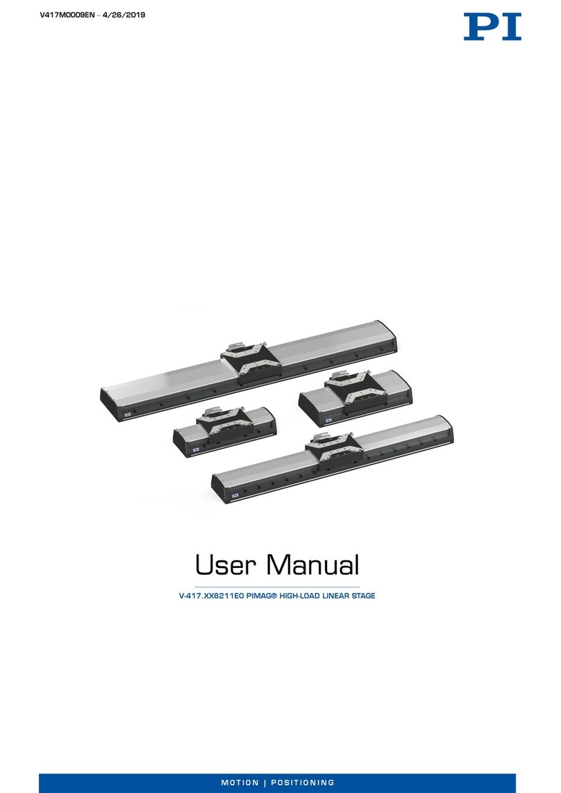
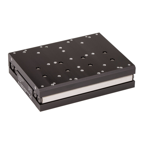
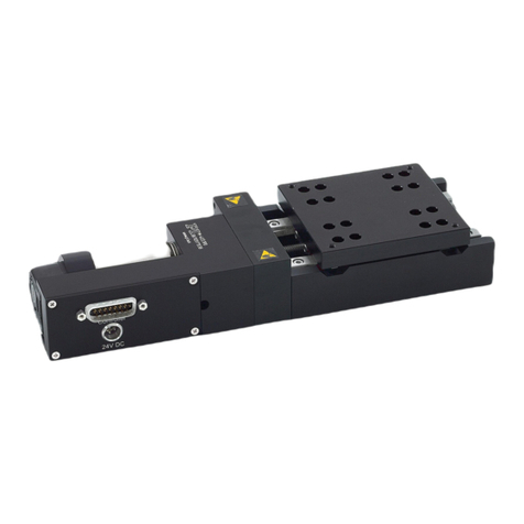
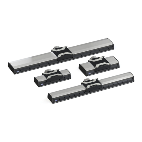
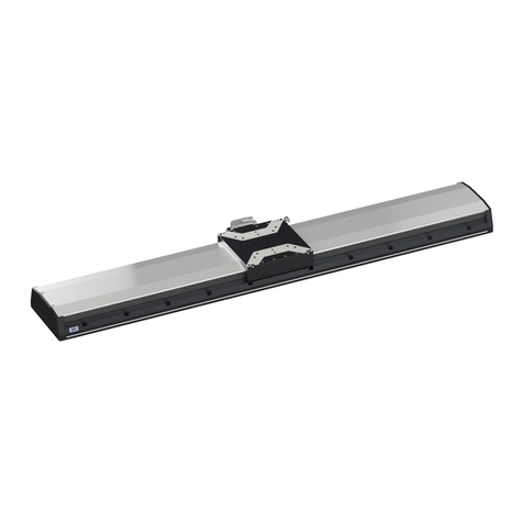
PI M-605 Series User manual

PI miCos GmbH, Freiburger Strasse 30, 79427 Eschbach, Germany
Phone +49 7634 5057-0, Fax +49 7634 5057-99, Email info@pimicos.com, www.pi.ws
MP45E
M
-605 High-Precision Linear Stage
User
Manual
Version: 1.2.0
Date: 2019-07-02
This document describes the following products:
M-605.1DD:
Compact precision linear stage, 25 mm travel
range, 0.1 μm linear encoder, ActiveDrive DC
motor
M-605.2DD:
Compact precision linear stage, 50 mm travel
range, 0.1 μm linear encoder, ActiveDrive DC
motor

The following company names and brands are registered trademarks of
Physik Instrumente (PI) GmbH & Co. KG:
PI®, NanoCube®, PICMA®, PIFOC, PILine®, NEXLINE®, PiezoWalk®, PicoCube®, PiezoMove®, PIMikroMove,
NEXACT®, Picoactuator®, PInano®, NEXSHIFT®, PITOUCH®, PIMag®, PIHera, Q-Motion®
The patents held by PI can be found in our list at http://www.physikinstrumente.com/en/about-pi/patents.
© 2019 Physik Instrumente (PI) GmbH & Co. KG, Karlsruhe, Germany. The text, photographs, and drawings in
this manual are protected by copyright. With regard thereto, Physik Instrumente (PI) GmbH & Co. KG reserves
all rights. The use of any text, images and drawings is permitted only in part and only when indicating the
source.
Original instructions
First printing: 02.07.2019
Document number: MP45E, ASt, Version 1.2.0
Subject to change. This manual is superseded by any new release. The latest release is available for download
from our website (p. Fehler! Textmarke nicht definiert.).

1About this Document 1
1.1 Objective and Target Group of this User Manual ...................................................... 1
1.2 Symbols and Typographic Conventions...................................................................... 1
1.3 Downloading Manuals................................................................................................ 2
2Safety 3
2.1 Intended Use .............................................................................................................. 3
2.2 General Safety Instructions ........................................................................................ 3
2.3 Organizational Measures............................................................................................ 3
3Product Description 5
3.1 Model Overview ......................................................................................................... 5
3.2 Scope of Delivery........................................................................................................ 5
3.3 Accessories ................................................................................................................. 5
3.4 Technical Features...................................................................................................... 6
3.4.1 Linear Scale Position Encoder........................................................................ 6
3.4.2 PWM Amplifiers............................................................................................. 6
3.4.3 Travel Limit Sensors....................................................................................... 6
3.4.4 Position Reference Signal Sensors................................................................. 6
4Unpacking 7
5Installation 9
5.1 General Notes on Installation..................................................................................... 9
5.2 Mounting the M-605 .................................................................................................. 9
5.3 Affixing the Load to the M-605 ................................................................................ 10
5.4 Connecting the M-605 to a Controller ..................................................................... 10
5.5 Connecting the Power Supply to the M-605 ............................................................ 11
6Startup 13
6.1 General Notes on Startup......................................................................................... 13
6.2 Starting and Operating the M-605 ........................................................................... 14
Contents

7Maintenance 15
8Troubleshooting 17
9Customer Service 19
10 Technical Data 21
10.1 Specifications............................................................................................................ 21
10.1.1 Data Table.................................................................................................... 21
10.1.2 Maximum Ratings........................................................................................ 22
10.1.3 Ambient Conditions and Classifications ...................................................... 22
10.1.4 Limit Switch Specifications .......................................................................... 23
10.2 Dimensions ............................................................................................................... 24
10.2.1 M-605.1DD .................................................................................................. 24
10.2.2 M-605.2DD .................................................................................................. 25
10.2.3 M-605.AV1................................................................................................... 26
10.3 Pin Assignment ......................................................................................................... 27
10.3.1 Controller Connector................................................................................... 27
11 Old Equipment Disposal 29
12 EU Declaration of Conformity 31

1 About this Document
M-605 High-Precision Linear Stage MP45E Version: 1.2.0 1
1.1 Objective and Target Group of this User Manual
This manual is designed to help the reader to install and operate the M-605 Linear Positioning
Stages. It assumes that the reader has a fundamental understanding of basic servo systems, as
well as motion control concepts and applicable safety procedures.
1.2 Symbols and Typographic Conventions
The following symbols and typographic conventions are used in this user manual:
CAUTION
Dangerous situation
If not avoided, the dangerous situation will result in minor injury.
Actions to take to avoid the situation.
NOTICE
Dangerous situation
If not avoided, the dangerous situation will result in damage to the equipment.
Actions to take to avoid the situation.
INFORMATION
Additional information that can affect your application.
Symbol / Label Meaning
1.
2.
Action consisting of several steps whose sequential order must be observed
Action consisting of one or several steps whose sequential order is irrelevant
24 V DC Labeling of an operating element on the product
Warning sign affixed to the product that refers to detailed information in this
manual.
1
About this Document

1 About this Document
2 Version: 1.2.0 MP45E M-605 High-Precision Linear Stage
1.3 Downloading Manuals
The devices and software tools from PI that are mentioned in this documentation are described
in separate manuals. The manuals are available for download on our website.
INFORMATION
If a manual is missing or problems occur with downloading:
Contact our customer service department (p. 19).
INFORMATION
For products that are supplied with software (data storage device in the scope of delivery),
access to the manuals is protected by a password. Protected content is only displayed on the
website after entering the access data. You need the data storage device for the product to get
the access data.
Downloading manuals
1. Open the website www.pi.ws.
2. If the product was shipped with a data storage device: Log into the website:
a) Click Login.
b) Enter the login data.
The login data is in the [...]_Releasenews_[...].pdf in the Manuals directory on the
data storage device.
If necessary: Follow the link and register yourself to get the login data
c) Click Login or press the Enter key.
3. Search for the product:
a) Click Search.
b) Enter the product number up to the period (e.g., M-605) into the search field.
c) Click Start search or press the Enter key.
d) If necessary: Click Load more results at the bottom of the list.
4. Click the corresponding product in the list of search results.
5. Click the Downloads tab.
The manuals are shown under Documentation.
6. Click the desired manual and save it.

2 Safety
M-605 High-Precision Linear Stage MP45E Version: 1.2.0 3
2.1 Intended Use
The M-605 is a laboratory device as defined by DIN EN 61010. It is intended for indoor use and
use in an environment which is free of dirt, oil, and lubricants.
In accordance with its design, the M-605 is intended for single-axis positioning, adjusting and
shifting of loads at different velocities. The M-605 is not intended for applications in areas, in
which a failure would represent severe risks to human beings or the environment.
The intended use of the M-605 is only possible when completely mounted and connected. The
M-605 must be operated with a suitable controller (p. 21). The controller is not in the scope of
delivery of the M-605.
2.2 General Safety Instructions
The M-605 is built according to state-of-the-art technology and recognized safety standards.
Improper use of the M-605 may result in personal injury and/or damage to the M-605.
Only use the M-605 for its intended purpose, and only if it is in perfect condition.
Read the user manual.
Immediately eliminate any faults and malfunctions that are likely to affect safety.
The operator is responsible for correct installation and operation of the M-605.
2.3 Organizational Measures
User manual
Always keep this user manual available when using the M-605.
The latest versions of the user manuals are available on our website (p. 2) for
download.
Add all information from the manufacturer such as supplements or technical notes to
the user manual.
If you give the M-605 to other users, also include this user manual as well as all other
relevant information provided by the manufacturer.
Only use the device on the basis of the complete user manual. Missing information due
to an incomplete user manual can result in damage to equipment.
Only install and operate the M-605 after you have read and understood this user
manual.
Personnel qualification
The M-605 may only be installed, started, operated, maintained, and cleaned by authorized and
appropriately qualified personnel.
2
Safety


3 Product Description
M-605 High-Precision Linear Stage MP45E Version: 1.2.0 5
3.1 Model Overview
Product number Description
M-605.1DD Compact precision linear stage, 25 mm travel range, 0.1 µm linear
encoder, ActiveDrive DC motor
M-605.2DD Compact precision linear stage, 50 mm travel range, 0.1 µm linear
encoder, ActiveDrive DC motor
3.2 Scope of Delivery
Product number Description
M-605.1DD
or
M-605.2DD
High precision linear stage, 25 mm travel range
or
High precision linear stage, 50 mm travel range
4295 Mounting kit, consisting of 4 metric screws M4x35 and a hex wrench
C-815.38 Motor cable D-Sub 15, 3 m
C-501.24050H Wide-range-input power supply 24 V DC / 50 W
3763 Power cord
K050B0002 Adapter for the power supply connection; barrel connector to
Switchcraft 3-pin connector (f)
MP119EK Short instructions for positioners with electric motors
3.3 Accessories
Accessories must be ordered separately.
Product number Description
M-605.AV1 Vertical mounting bracket for M-605 to M-605
M-110.01 Adapter plate for mounting M-110 - M-112, F-130, F-131 and M-605
stages onto honeycomb stages (metric and inches)
3
Product Description

3 Product Description
6 Version: 1.2.0 MP45E M-605 High-Precision Linear Stage
3.4 Technical Features
3.4.1 Linear Scale Position Encoder
M-605 stages use linear scale position encoders with 0.1 µm resolution for position detection.
Maximum velocities of 50 mm/s can be achieved.
The linear encoder is mounted in the center of the stage, close to the ballscrew drive to prevent
possible cosine error. The linear encoder measures the actual position of the moving carriage
directly, thus eliminating drivetrain errors such as non-linearity, backlash or elastic
deformations.
The encoder is based on an optical grating and a non-contacting read head with integrated
signal conditioner and interpolator.
3.4.2 PWM Amplifiers
For maximum dynamic performance, the DC servo-motors are driven by high-efficiency PWM
power amplifiers integrated into the stages. An external line-power power supply (order
number: M-500.PS) is provided to supply the built-in amplifiers directly. This architecture allows
high torque and high velocities while loading the motor controller with control signals only. The
actual power is provided by the external supply.
3.4.3 Travel Limit Sensors
M-605 stages are protected against running into the hard stop by double-level magnetic limit
sensors (Hall-effect sensors with TTL drivers) at each end of travel.
The inner limit sensors (N1 at the negative-travel end and P1 at the positive-travel end) work
with the controller's limit sense input lines. The TTL output signal is active high.
The outer limit sensors (N2 at the negative and P2 at the positive end) work locally, opening a
relay that cuts the motor current. The second-level limit switches provide for fail-safe operation
in case the controller fails to stop the motor when the inner limit sensor is reached.
If the outer limit switch is reached, the stage can not be operated by the controller until the
platform is moved manually. Disconnect the motor cable or set the motor into MOTOR OFF
state before moving the platform back into the current-allowed area via the rotary knob.
3.4.4 Position Reference Signal Sensors
Position Reference Sensors are located approximately in the middle of the operating range and
can be used to reference the absolute position of the stage. Always approach the reference
sensor from the same side to reach the same position.
The reference sensor in M-605 stages provides a static signal level which depends on the
platform position. If the platform is on the “positive side” the reference signal is +5 V, while if
the platform is on the “negative side,” the signal level is 0 V. Most PI motor controllers and
Windows libraries offer the option of starting a search run for the reference point using the
current reference sensor signal to determine the appropriate direction.
The "AutoFindReference" function allows for starting a search run for the reference signal.
Independent at which side relative to the reference position the stage is located, this function
always starts the stage towards the reference position.

4 Unpacking
M-605 High-Precision Linear Stage MP45E Version: 1.2.0 7
1. Unpack the M-605 with care.
2. Compare the contents with the items listed in the contract and the packing list.
3. Inspect the contents for signs of damage. If there is any sign of damage or missing parts,
contact PI immediately.
4. Keep all packaging materials in case the product needs to be returned.
4
Unpacking


5 Installation
M-605 High-Precision Linear Stage MP45E Version: 1.2.0 9
5.1 General Notes on Installation
CAUTION
Risk of crushing by moving parts!
Risk of minor injuries from crushing between the moving parts of the M-605 or the load and a
fixed part or obstacle.
Use safeguards to protect limbs in areas where they could be caught by moving parts.
Maintain the safety distances according to DIN EN ISO 13857 when installing protective
structures.
CAUTION
Risk of injury or damage if anything is put on the bellows!
Putting anything on the bellows can cause injury or damage.
Do not put anything on the blellows.
5.2 Mounting the M-605
M-605 stages can be mounted in any orientation, horizontally or vertically. To achieve the
specified guiding accuracy, the stages must be mounted on an even surface to avoid torsion of
the base.
Requirements
You have read and understood the general notes on installation (p.9).
The place of installation is in a clean environment.
Although provided with a flexible bellows to protect against dust and liquids, the unit is
not hermetically sealed. Make sure that metal dust and liquid spray do not enter the
case.
You have provided a suitable surface with a flatness of ≤ 50 μm.
For the required position and depth of the holes for accommodating the screws and
locating pins, see "Dimensions" (p. 24).
Tools and accessories
Mounting kit; in the scope of delivery (p. 5)
−4 metric screws M4x35
5
Installation

5 Installation
10 Version: 1.2.0 MP45E M-605 High-Precision Linear Stage
−Hex wrench
Mounting the positioner onto a surface
1. Place the positioner on the surface so that the corresponding mounting holes in the
positioner and the surface are in line.
2. Tighten all screws in the mounting holes selected.
3. Check that the positioner is affixed firmly to the surface.
5.3 Affixing the Load to the M-605
Requirements
You have read and understood the general notes on installation (p. 9).
You have mounted the stage onto a surface properly (p. 9).
The stage is not connected to the controller.
You have prepared the load so that it can be affixed to the mounting holes on the upper
platform (p. 24).
Tools and accessories
At least 2 metric screws M4x35
Hex wrench; in the scope of delivery (p. 5)
Affixing the load
1. Align the load so that the selected mounting holes in the platform can be used to affix
it.
2. Use the screws to affix the load on the selected mounting holes in the platform.
3. Check that the load is affixed firmly to the platform of the positioner.
5.4 Connecting the M-605 to a Controller
Requirements
You have read and understood the general notes on installation (p. 9).
You have installed the controller.
You have read and understood the user manual for the controller.
The controller is switched off.
Tools and accessories
Motor cable; in the scope of delivery (p. 5)

5 Installation
M-605 High-Precision Linear Stage MP45E Version: 1.2.0 11
Suitable tool for tightening the screws of the connector
Connecting the M-605 to a controller
1. If necessary: Remove the protective caps from all connections of the M-605.
2. Connect the M-605 and the controller to each other by means of the motor cable.
3. Use the integrated screws to secure the connections against accidental disconnection.
5.5 Connecting the Power Supply to the M-605
Requirements
The power cord is not connected to the power socket.
Tools and accessories
Supplied components; in the scope of delivery (p. 5):
−Wide-range-input power supply
−Adapter for the power supply connection; barrel connector to Switchcraft 3-pin
connector (f)
−Power cord
If one of the components supplied for connecting to the power supply has to be
replaced: Use a sufficiently rated and certified replacement component.
Connecting the power supply to the M-605
1. Connect the adapter's Switchcraft connector (f) to the M-605's 24 V DC panel plug.
2. Connect the adapter's barrel connector to the power supply's barrel connector socket.
3. Connect the power cord to the power supply.


6 Startup
M-605 High-Precision Linear Stage MP45E Version: 1.2.0 13
6.1 General Notes on Startup
CAUTION
Risk of crushing by moving parts!
Risk of minor injuries from crushing between the moving parts of the M-605 or the load and a
fixed part or obstacle.
Never put your finger anywhere where the moving platform or any connected object could
possibly trap it.
NOTICE
Damage due to collisions!
Collisions can damage the positioner, the load to be moved, and the surroundings.
Make sure that no collisions are possible between the positioner, the load to be moved,
and the surroundings in the motion range of the positioner.
Do not place any objects in areas where they can be caught by moving parts.
Stop the motion immediately if a controller malfunction occurs.
If possible, adapt the travel range limits of your mechanical system in the software you use
for commanding the motion.
NOTICE
Unintentional motion!
M-605 stages are powered by powerful electric motors and can accelerate to high speeds. Be
aware that automatic limit switch halt may not be supported by, or activated at, the motor
control electronics. Be aware that failure of the motor controller may drive the stage into a
hard stop at high speeds.
Unintentional motion of the M-605 is possible when it is connected to the controller.
Do not place any objects in areas where they can be caught by moving parts.
Before connecting the M-605, check whether a macro is defined as the startup macro in
the controller, and cancel the selection of the startup macro if necessary.
6
Startup

6 Startup
14 Version: 1.2.0 MP45E M-605 High-Precision Linear Stage
6.2 Starting and Operating the M-605
Requirements
You have read and understood the general notes on startup (p. 13).
You have installed the stage properly (p. 9).
You have read and understood the user manual for the controller used.
You have read and understood the manual for the PC software used.
The controller and the required PC software have been installed.
Starting and Operating the M-605
1. Start the controller (see user manual for the controller).
2. Configure the controller for the M-605 during startup:
−If you are using a digital controller from PI: In the PC software, select the entry in
the positioner database that matches the used M-605 model exactly.
−If you are using a controller from another manufacturer: Configure the controller
according to the parameters of the M-605 model used.
3. Start a few motion cycles for testing purposes (see user manual for the controller).

7 Maintenance
M-605 High-Precision Linear Stage MP45E Version: 1.2.0 15
When operated in a clean environment, no maintenance is required.
If the stages are operated in extremely dusty environments, we recommend cleaning and
greasing the ballscrew and linear bearings from time to time. The time interval depends on the
degree of contamination and can vary from 100 to 800 operating hours.
Recommended lubricant for ballscrews:
KLÜBER Staburags Type NBU 8EP or Beacom 325
7
Maintenance

This manual suits for next models
2
Table of contents
Other PI Valve Positioner manuals

PI
PI PIMAG V-412.xx6025E0 Series User manual

PI
PI PIMAG V-417.6211E0 Series User manual

PI
PI NEXACT Stage N-565 Series Manual

PI
PI F-712.MA1 User manual

PI
PI UPL-120 Manual

PI
PI P-62 Series User manual

PI
PI L-306 Series User manual

PI
PI M-110.*DG1 series User manual

PI
PI P-63 Series User manual

PI
PI P-73 Series User manual
Popular Valve Positioner manuals by other brands

Samson
Samson 3730-4 Original instructions

Baker Hughes
Baker Hughes Masoneilan SVIII AP Installation and maintenance manual

PS Automation
PS Automation PSAP.2 installation instructions

STI
STI IMI FasTrak Compact FTC-I instructions

Bifold Orange
Bifold Orange EX200 Operation, installation, and maintenance manual

Ytc
Ytc YT-1000R troubleshooting manual