ALFAMATIC Visual Point User manual

Jun. 7, 2013
Visual Point
Version 1.60
User manual

2
1Introduction.............................................................................................................................3
1.1 Control theory................................................................................................................................... 3
1.2 OPERATING ABILITY OF THE INSTRUMENT ...................................................................... 3
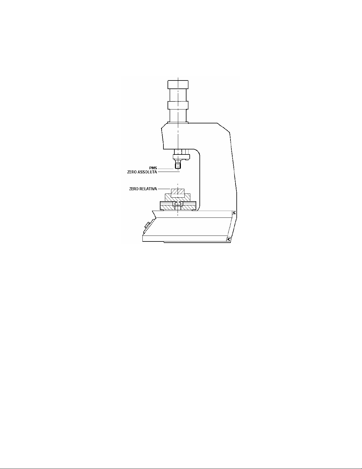
1.3 Start position ..................................................................................................................................... 4
1.4 Absolute or relative positions .......................................................................................................... 5
2Implementation of VISUAL POINT........................................................................................6
3HOW TO BEGIN ....................................................................................................................7
3.1 INTRODUCTION FOR THE USE OF VISUAL POINT............................................................. 7
3.2 ENTERING OF A VALUE.............................................................................................................. 8
3.3 THE WORK...................................................................................................................................... 8
3.4 GETTING ACCUSTOMED TO THE INSTRUMENT................................................................ 8
3.5 REJECTED PIECES MANAGMENT ........................................................................................... 9
4MENU DESCRIPTION ........................................................................................................10
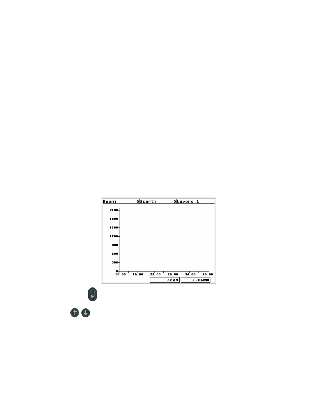
4.1 MEASUREMENTS ........................................................................................................................ 10
4.2 SELECT WORK ............................................................................................................................ 12
4.3 EDIT WORK .................................................................................................................................. 12
4.4 GRAPH SETUP .............................................................................................................................. 14
4.5 PRINT.............................................................................................................................................. 14
4.6 GOOD .............................................................................................................................................. 15
4.7 REJECTED..................................................................................................................................... 15
4.8 COONTRAST................................................................................................................................. 15
4.9 CONFIGURATION ....................................................................................................................... 15
5WORK PARAMETER...........................................................................................................18
5.1 STOP VALUES............................................................................................................................... 18
5.2 Check point ..................................................................................................................................... 18
5.3 Limits ............................................................................................................................................... 19
6Configuration ........................................................................................................................21
6.1 Ethernet connection........................................................................................................................ 22
7Calibration ............................................................................................................................23
7.1 Force transducer calibration ......................................................................................................... 23
7.2 Position transducer calibration ..................................................................................................... 23
7.3 Encoder calibration ........................................................................................................................ 24
7.4 Potenziometer calibration.............................................................................................................. 24

3
1 Introduction
The VISUAL POINT is a device that allows for a 100% quality check of the production process.
It is connected with a power transformer, actuators and display (light display or acoustic signals).
Esistono due versioni di VISUAL POINT: per montaggio esterno con contenitore (Picture 1); per
montaggio a pannello (Picture 2).
The interface for the user is the operating front which consists of a display and a membrane
keyboard.
Picture 1
Picture 2
1.1 Control theory
While working on a sample pieces there are data on the position of the cylinder and the force
exerted by it. You can draw the graph: position-force that is characteristic of work done.
If more operations are performed on similar pieces their position-forced curves will also be similar.
If, on the contrary, one of the pieces will be different from the sample, the curve will deviate from
the sample curve. It is as intuitive control of the curve can ensure consistent quality of
workmanship
1.2 OPERATING ABILITY OF THE INSTRUMENT
The VISUAL POINT features various operation possibilities. The set process check occurs on the
basis of checkpoints and limits. All operation parameters are saved in an internal, not regenerative
memory. Up to 32 different settings can be saved. Every setting is called work (see paragraph 3.2).
A change to the checkpoints (section 5.2) allows the measurement and control of the force at a
certain position of the set path. The force must lie between the minimum and maximum value.
The following maximum value (paragraph 5.3) can apply: Minimum force, maximum force,
minimal set path and maximum set path; these control the maximum values achieved during the
force and set path operation. Should the maximum force achieved not lie above the minimum force
or exceed the maximum force, then the part is rejected. And if the maximum set path achieved does
not lie above the minimum set path or exceeds the maximum set path, the part is likewise rejected.
There are two other limits: the initial position minimum and initial position maximum, if the initial
position (see paragraph 1.3) is less than the minimum or is higher than the maximum the piece is
discarded
The part is only regarded as good if the forces contain a positive result at the checkpoints as well as
at the limits.
The VISUAL POINT carries out the control of the cylinder retraction, as soon as the operation is
shut down (see section 5.1). This retraction can occur if a certain force or if a certain set path is

4
reached. Both force and set path shut-down values can be entered at the same time, in which case
the first value achieved retracts the cylinder. By pressing of the RESET button on the keyboard,
the possibility of an immediate retraction of the pressing ram (annulment of the process) exists.
1.3 Start position
The VISUAL POINT is able to detect the position in which the press touches the workpiece. This is
known as start position and corresponds to the approaching stroke. To survey the start position,
the load cell is used: when the force measured by the load cell exceeds the value of zero force
(paragraph 4.3.4) is measured the start position.
The accuracy of the start position depends on the speed of the cylinder and especially on the type of
workpiece. For example, in the operations of shrinking the two pieces have rounded corners, so the
starting position varies with the bevel and strength that is used to in the first place a piece of work.
Note:
The VISUAL POINT used with manual presses is capable of measuring the start position during
the descent of the stem.

5
1.4 Absolute or relative positions
The position of the cylinder is detected by a transducer. The positions measured by the transducer
are called absolute positions. The positions measured from piece contact are called relative
positions. The VISUAL POINT can use absolute or relative positions (see Figure 3).
Figure 3
1.4.1 Check point on the stop position
The position of the checkpoint may be related to the final of the pressfit.
In practice, if I enable the option to use check points on stop, the positions of measuring forces are
calculated by working backward from the quota that has been driven to stop.
For example, if I point a controlling stake in a check point equal to 1 mm, the instrument will
measure and monitor at the end of processing, strength 1mm before the final installment of the
production.

6
2 Implementation of VISUAL POINT
For installation of VISUAL POINT on the machine refer to the specific manual.
The VISUAL POINT is available in two versions: with box and for panel mounting.
The version with the box can be mounted inside a power supply to operate without electrical panel.

7
3 HOW TO BEGIN
This chapter serves as quick instruction for the immediate use of VISUAL POINT. A short
functional description of the instrument is followed by a chapter that accompanies you through the
execution of a few tests. To follow this guide you need to get some pieces to assemble the evidence
into practice.
Note:
The stop of the press is controlled by VISUAL POINT.
Should the value of a parameter with zero be entered, then this will not be used by the
instrument.
The configuration and taring values cannot be coincidently changed without entering the
configuration password (see chapter Errore. L'origine riferimento non è stata trovata.)
A password can be also generated in order to prevent a change in the working parameters (see
chapter Errore. L'origine riferimento non è stata trovata.)
3.1 INTRODUCTION FOR THE USE OF VISUAL POINT
To turn the instrument on, there is a switch at the back of the instrument. When it is switched on,
the axes of the force stroke graphic appear on the display. Above the graphic there are three fields
which contain the part numbers and the names of the selected work. Below the graphic, there are
two framed fields which contain the measured force value as well as the value measured by the
travel measuring system of the force sensor in actual time.
In the graphic, the curve is only captured if it is within the full scale value of the axes. Of course
these values can be altered.
When the ENTER button is pressed, a menu window that contains an item list will appear on
the display. An item on this list is highlighted by a black bar; with the arrow buttons upwards and
downwards , the bar is able to be moved and it will run through all the items on the menu.
To execute a command of one of the highlighted items, the ENTER button must be pressed.

8
If you leave the menu or change a value that you would like to cancel, you can simply press the
RESET button. The item ‘exit’ is also included in the sub-menus and allows you to return to
the previous menu where the function is identical to pressing the RESET button.
In order to display the graphic and the curve momentarily without exiting the menu, the RESET
button must be pressed for a few seconds.
3.2 ENTERING OF A VALUE
A value can be entered if the figure to be changed is displayed in a window, with the description
and the number to be changed. A digit of the value to be changed is highlighted on the cursor by a
small black rectangle:
The value can be changed by using the keyboard, which must always be accepted by pressing the
ENTER . The arrow keys have the following functions during value input:
increases the digit highlighted by the cursor (in the representation one becomes two).
decreases the digit highlighted by the cursor (in the representation one becomes zero).
moves the cursor to the left (in the representation the cursor moves to the +symbol).
moves the cursor to the right (in the representation the cursor moves to the right, to the zero).
To change the sign of the value, move the cursor to the sign and press the or .
For a momentary display of the graphic and the curve without exiting the menu, press the RESET
for a few seconds.
3.3 THE WORK
The VISUAL POINT has the capacity to save 32 different work settings. Each setting is called
work and a name can be assigned to every work as a description. The choice of work to be
performed takes place via the appropriate sub menu. In order to add a work, change a name or
selection see the menu Select work. In order to change or eliminate a work in progress, see the
menu select work. Every work has various parameters, as described in Chapter 5.
3.4 GETTING ACCUSTOMED TO THE INSTRUMENT
In order to perform tests with the VISUAL POINT, one can proceed as follows: after turning the
instrument on, press the ENTER button to go to the menu. Run through the menu items by pressing
the buttons until the edit work item, which contains all the settings of the work in process
is reached. Now in the edit work menu, with the help of the arrow keys , move up to the

9
item stops; and press the ENTER button to reach in the sub menu which contains the setting of the
Fstop and the Sstop.
Point the item force Stop and press the ENTER button to change its value. Enter a value of force
below the maximum force of the press.
Once you modify the parameters, to exit the menu, select Exit or press the RESET button.
Now the press can be started; the press remains in operation until the Fstop entered is reached. In
order to stop the press before the reaching the Fstop, the RESET button can be pressed.
Should the pressing ram of the press have returned to the starting point, then the menu
Measurements can be selected in order to indicate the measured values.
In order to view the curve in the Stroke force graph, the beginning and ending chart must be entered
into the sub menu Graph setup which is in the main menu.
To choose which values we use to enter your measured values shown in the menu Measures: The
start position S.Zero shows the position of value measured when the piece has been touched, we
will use a position slightly less than this as the origin of the graph.
The peak position S.max indicates the maximum achieved position value, we will use a scale larger
of this value. The peak force F.max indicates the maximum force value reached, we will use a
scale of force larger of this value.
If we repeat the test on another similar piece we see the position-force curve. We can now improve
the display touching the values of the chart menu and then navigate to the definition of the work
parameters that determine whether the workpieces are good or rejected as explained in Chapter 5.
3.5 REJECTED PIECES MANAGMENT
Should, for various reasons, the part be rejected, then one can proceed to the Measurements menu
and view the individual reasons using the arrow keys .
When a piece is rejected the machine locks. To re-enable it, there are several options: if the
machine is equipped with a rejects basket should pass the piece through the sensor of the basket, if
there is also protection must first press RESET button to open it, then the piece must pass through
the sensor of the basket rejects, if the machine does not have these variants simply press RESET
or, if present, to re-enable the external switch.

10
4 MENU DESCRIPTION
Note:
It is possible hiding items menu used infrequently by turning on the instrument while holding
pressed the RESET button. To restore the full menus do the same.
When pressing ENTER button, a menu window which contains a concept list appears on the
display.
An item on this list is highlighted by a black bar; with the arrow buttons upwards and downwards
, the bar is able to be moved and it will run through all the items on the menu. In order to
activate the command of the item highlighted by the bar, the ENTER button must be pressed.
The items which have a small triangle on the right are selected, access sub-menus when the
ENTER button is pressed.
Other items include a value measured by the instrument (for e.g. number of good/rejected parts).
Others indicate the value of an operation parameter, that the operator can change.
Items which include a rectangle on the left side are options which can be activated or deactivated
with the use of the ENTER button.
If you leave the menu or change a value that you would like to cancel, you can simply press the
RESET button. There is also the exit item in the menu which allows you to return to the
previous menu.
Note:
If the RESET button is pressed for two seconds, the graphic with the curve and the parameters
entered can be viewed and the menu is momentarily covered without leaving the actual
menu.
In the following sections, the menu items and their function descriptions are performed.
4.1 MEASUREMENTS
By selecting the item Measurements, you will arrive at a sub-menu which contains all the values
measured in the last press cycle.
In the following illustrations we have the process curve on the left and the VISUAL POINT
measurement values for the curve on the right:

11
The following items are included in the Measurements menu:
4.1.1 Result
Result indicates whether a part is good or the possible reasons why it is rejected. If there is more
than one reason for the part to be rejected, then the arrow keys can be used to indicate the
reasons one after the other.
The following items could appear depending on the circumstances:
-Good: il pezzo è risultato buono.
-No F.min: The part is scrap because the maximum force did not reach the minimum force value
entered.
-Exc.F.max:The part is scrap because the maximum force has exceeded the maximum force
value entered.
-No S.min:The part is scrap because of the maximum stroke has not reached the minimum
stroke entered. Should the minimum stroke limits have not been entered, then the part is scrap
because the maximum stroke has not reached the checkpoint, provided one was defined.
-Exc.S.max: The part is scrap because of the maximum stroke has exceeded the highest stroke
limit.
-No S.zero:the piece is rejected because the start position is less than the minimum limit.
-Exc.S.zero: the piece is rejected because the start position is great than the maximum limit.
-F. low n: The part is scrap because the force at the checkpoint lies below the fixed minimum
force value.
-F. high n:The part is scrap because the force at the checkpoint lies above the fixed maximum
force value.
-Stop: It appears that the test has been manually interrupted, i.e. the idleness of the press is not
controlled by VISUAL POINT.
4.1.2 F.reached
The value of the maximum force achieved during the last test. This value is checked with the aid of
the minimum and maximum force limits.
4.1.3 P. reached
The value of the maximum stroke achieved during the last test. This value is checked with the aid
of the Minimum and Maximum stroke.

12
4.1.4 P.Zero
The value of the position determined by the force sensor, when setting tool comes into contact with
the part (vedi capitolo 1.3).
4.1.5 F.check n
The force value captured from the stroke at the checkpoint. This item allows the access to a sub-
menu which transmits the statistical values of the corresponding checkpoint. In the sub-menu of the
statistical values, the average force at the checkpoint (F.min. CP), the number of scraps due to a
too great force (n. NIO.F.max) and due to a too low force (n. NIO.F.min) are contained. These
values are reset, when the tally of good parts and scrap parts are reset.
4.1.6 Good
Number of completed good parts. The counter remains saved in memory when the instrument is
switched off. To reset the counter back to zero, press the ENTER button. By zeroing the counter,
the calculated average values also become zero.
4.1.7 Rejected
Number of completed parts that are scrap. The counter remains saved in memory when the
instrument is switched off. To reset the counter back to zero, press the ENTER button. By zeroing
the counter, the scrap counters at each checkpoints also become zero.
4.2 SELECT WORK
In the ' select work ' menu, the directory of all the available work that is saved on the instrument is
displayed.
When viewing this menu, the most current work is highlighted. By selecting the most current work,
the name of the description can be changed.
To eliminate a work, one must select the menu ' select work' (see section 4.3.6).
4.2.1 Creating a new work
Using this item, a work can be added to the list. The new work will be empty. If a new work is
created, an identification will be required.
4.2.2 Create a copy
Using this item, a work can be added to the list. The new work will be identical to the work in use.
If a new work is created, an identification will be required.
4.3 EDIT WORK
In the sub-menu you can enter all the work parameters and options that the instrument is to use
during the operation. The changes will refer to the task in operation at that moment.
4.3.1 Stops
When this item is selected, you can determine idle force and stroke (see chapter 5.1). To use no idle
value, simply do not enter a value (zero).
-F.Stop: is the force value with which the press becomes disengaged into the idle position.
-P.Stop:is the stroke with which the press becomes disengaged into the idle position.
-Stop delay:is the time in which the shut-down can be delayed.

13
4.3.2 Check point n
The checkpoint allows for the inspection of the curve progression and requires the input of three
parameters:
-P.check: is a value that lies between the start of the stroke and before the final stroke value,
where the measurement of the controlling force takes place. If the option relative checkpoint on
end is activated (see Section 4.3.5) this value will indicate the position of measurement refers to
the end of the pressfit.
-F.min: is the minimum value of the force which is measured at the measurement point S.check.
The measured force must lie above this value in order to achieve a good part.
-F.max:is the maximum value of the force which is measured in the measurement point
S.check. The measured force may not lie above this value to achieve a good part.
If a value of zero is entered for the stroke, the checkpoint is excluded from the inspection.
The force measured at the checkpoint can be viewed in the menu Measurements. The checkpoints
will only appear in the graphics if the stroke endpoint becomes known, i.e. at the end of the task.
If you activate the option Quote for the check point check point will be displayed on the graph
will be known only when the final position of pressfit, so after work.
4.3.3 Limits
The limit values control the force and the maximum stroke (see chapter 5.3).
-F.min: is the minimum force which must be achieved to receive a good part.
-F.max: is the maximum force which may not be exceeded in order to receive a good part.
-P.min: is the minimum stroke which must be achieved in order to receive a good part.
-P.max: is the maximum stroke which may not be exceeded in order to receive a good part.
-SetPoint: is the value attack signal SETPOINT. The SetPoint item is visible only if the device
is configured to control its output power.
4.3.4 Start position
The Start position is detected by the instrument when the force measured by the load cell exceeds a
threshold value (see Section 1.3). This menu allows the insertion of the minimum and maximum
limits for the Start position insertion of the force threshold for detecting the same.
-P.min: the input of the stroke for the minimum value to be reached for a good part.
-P.max: the input of the stroke for the maximum value to be reached for a good part.
-F.d’inizio: to start the Press action with the minimum necessary force for the stroke on the
expander sphere.
If the instrument is not configured for the control of SETPOINT, the output SETPOINT is activated
when the force measured by the load cell exceeds a threshold value.
4.3.5 Options
Each work in its options that govern the operation to be performed.
-Use relative positions: see chapter 1.4.
-Stop if low start position: Press stops and return when start position value measured is too low.
-Stop if wrong checkpoint: Press stops and return when start position value measured is too
high.
-Stop if wrong checkpoint: Press stop and return to start position when checkpoint is non-
compliant.
-Relative positions checkpoint: This option changes the method for calculating the positions of
the check point. Activating this option will check the force at position from the final position
value. Of course, force control will be executed only after the arrest of the press.
-Manual work: This option is only available with the presses that have to manually approach
through the lever. In presses with manual approach may be that the piece is partially pressed

14
simply exerting a force on the lever. Enabling this option, the control curve is also during
lavvicinamento with the lever, before the press is actually started.
-Ask password with rejected pieces: activating this option you are prompted to enter your
password to unlock do rehabilitating the instrument in case of rejected piece.
4.3.6 Delete work
When selecting this command, the work in process is deleted after quitting. When deleting the last
available work, the name of the new work which is to be created, is required.
4.4 GRAPH SETUP
In the configuration menu, the scale of the axes 'Force end scale' and ‘Position end scale' can be
changed in the graphic.
4.4.1 Position origin
The 'Position origin' is the initial value displayed in the graphic. In the illustration this value is
10.00mm.
4.4.2 Position end scale
The 'Position end scale' is the maximum stroke displayed in the graphic. In the illustration, this
scale end value is 40.00mm.
4.4.3 Force end scale
The 'Force end scale' is the maximum set force displayed in the graphic. In the illustration, the scale
end value is 2100 daN.
4.5 PRINT
The menu for printing is only visible if the instrument was configured for the use of a printer.
4.5.1 Printing statistics
Starts the print of the part counter and the statistical values.
4.5.2 Printing measured values
Starts the print of measured values for the last part worked on.

15
4.5.3 Print if part is good
If this option is activated, then the measured values of every good part are printed.
4.5.4 Print if part is rejected
If this option is activated, then the measured values of every scrap part are printed.
4.6 GOOD
Identical to the item Measurement results in the menu, which is described in section 4.1.6.
4.7 REJECTED
Identical to the item Measurement results in the menu, which is described in section 4.1.7.
4.8 COONTRAST
The contrast setting on the display allows for an optimum display. Upon selecting the item, one can
raise the contrast making the screen darker with the help of the button , and one can decrease
the contrast making the screen brighter with the help of the button. To exit, press the ENTER
button.
4.9 CONFIGURATION
VISUAL POINT can be set-up according to your requirements, using the configuration menu.
4.9.1 Password parameter
A password can be entered to change all operating parameters or changed. At the request and the
correct password input, the following icon appears on the display. To reset the password, one
must exit all menus and press the RESET button.
4.9.2 Password unlock
Allows insertion and changing the password used to unlock the device in the event of a rejected
piece of work when the option is turned on.
4.9.3 Password calibration
Allows changing the password prevents access to the configuration menu of the instrument. When
prompted for this password, and fits properly on the display the icon . To reset the password you
need to exit any menu and press the RESET button. The factory set password is 9724.
4.9.4 Info
Indicates the number total of pieces worked and the firmware version in both of the instrument
CPUs.
4.9.5 Type of machine
Allows editing of the configuration options of the instrument. These depend on the connected
machine and the type of operation required. For a description see chapter 6.

16
4.9.6 Diagnosis
The serviceability of the force and travel encoders can be inspected via the diagnostics window.
The serviceability of the inputs and outputs can also be inspected.
The diagnostics window is divided into three sections:
Section Transducers
In this section the digital value of the force transducer appears on the left. By changing the force
offset, this value can be brought to zero.
The force measurement value is displayed at the bottom in a size that is easier to manage. The
digital value is multiplied with the force factor in order to achieve this value. The taring can be
changed together with the offset and factor of the measuring units as well as the number of the
decimal digits.
In the transducers section the digital value of the position transducer appears on the right. By
changing the stroke offset, this value can be brought down to zero.
The position measuring value is displayed at the bottom in a size that is easier to manage. The
digital value is multiplied with the stroke in order to achieve this value The taring can be changed
together with the offset and factor of the measuring units as well as the number of the decimal
digits.
One can reach the taring menu by moving the cursor in this section.
Section Input
The state of the input signals are indicated in the middle section. If an input is active, the number is
highlighted by a black rectangle. In the illustration above, the input 1 is active.
Section Output
The state of the output signals are indicated in the middle section. If an output is active, the number
is highlighted by a black rectangle. In the illustration above, the output 3 is active.
An output can be changed by moving the cursor (black rectangle) onto the desired source number
and pressing the ENTER button.
Changing the outputs can be dangerous.
4.9.7 Calibration
With the help of the taring menu, the transducers can be calibrated and changed to indicate both of
the instrument sizes used (Force and stroke).
-S.Offset: is the value which is deducted from the position transducer value on the display.
-S.Gain: is a factor by which the position transducer value is multiplied on the display.
-S.Decimals: allows the determining of the number of the digits after the comma which are to be
used for all stroke values. Up to three digits can be displayed.
-S.dim.unit: allows the choice of desired measurement units for the stroke values: millimetre
(mm) or inch (in).
-F.Offset: is the value on the display which is deducted from the force transducer value.
-F.Gain: is the factor on the display by which the force transducer value is multiplied.

17
-F.Decimals: allows the determining of the number of digits after the comma which are to be
used for all force values. Up to three digits can be displayed.
-F.dim.unit: allows the selection of the desired measurement units for the force values:
decaNewton (daN = approx. 1 kg), kiloNewton (KN = approx. 100 kg)
4.9.8 Enable printer
A printer that prints on striped paper or labels can be connected. When connecting a printer to the
instrument, this option must be activated.
Note:
Only special printers can be connected: for more information contact the Alfamatic.
The connection of a printer excludes the possibility of using the ExPress together with a
computer and screen, because only one serial interface RS232 exists.
4.9.9 Date
This item is visible only if the clock is equipped with VISUAL PONT.
With this item you can set the date and time that will be used in printing.
4.9.10 Reset memory
In the VISUAL POINT is a nonvolatile memory that retains the settings of the instrument and
counter parts: with this command you can erase this memory.
If you erase the memory of the instrument, you will have to repeat all the calibration
and configuration of the instrument.

18
5 WORK PARAMETER
The parameters available for work are: Shut-down values, checkpoints and maximum values. To
display changes or remove parameters, one must view the menu. The stroke force curve is captured
by VISUAL POINT and depends on the characteristics of the work piece. One must enter the
working parameters in order to separate the curves of good parts from those of scrap parts.
5.1 STOP VALUES
The shut-down values determine whether the process of the pressing ram is stopped and returned.
The return can be actuated if a certain force or a certain stroke is achieved. If the force or the stroke
exceeds these shut-down values, the instrument triggers the return of the pressing ram.
Picture 4
When both values are entered, if at least one value is exceeded (first-achieved), then the press will
be shut-down.
On account of the delay times of hydro pneumatic components, the shut-down occurs a little
delayed compared to the control via the instrument. It is normal that the captured effective values
achieved exceed the programmed shut-down values. If a value is set to zero, it is ignored, if both
values are set to zero, the shut-down occurs via VISUAL POINT; in this case, one must press the
RESET for the unit to return. If the workpiece has not a mechanical stop, it is best to use a
stop mounted on the press. If you can not work with a mechanical stop is possible to equip the press
with a deceleration to slow the speed of the stem in the last section of the press. The VISUAL
POINT can activate the decelerator settable position. The value of this share will to be slightly
smaller than the percentage arrest.
5.2 Check point
The checkpoint serves for the measurement and the inspection of the force in a certain position on
the press. The forces measured on a specific stroke must lie between the minimum and maximum
force.
Every checkpoint requires the input of three parameters:
-The measuring position 1, i.e. the position at which the force is to be measured: S.check.
-The minimum value of the force measured on the measuring position is: F.min.
-The highest value of the force measured on the measuring position is: F.max.

19
If the stroke value is set to zero, the checkpoint is excluded from the inspection.
If you activate the option Quote for the check point check point will be displayed on the graph
will be known only when the final position of pressfit, so after work.The work piece is only then
classed as a good part if the force lies within the corresponding maximum ratings at the checkpoint.
Picture 5
The force measured at the checkpoint is indicated in the Measurement menu (see section Errore.
L'origine riferimento non è stata trovata.).
5.3 Limits
The following limits can exist: minimum and maximum force, minimum and maximum stroke;
these control the maximum forces and strokes achieved during the operation.
There are two other limits: minimum and amximum start position that controls the start position
value (see paragraph 1.3).
5.3.1 Minimum and maximum limits
When the force reached Maximum (peak) does not exceed the minimum or exceed the maximum
force the piece is rejected. Similarly, if the maximum position (peak) achieved no more than the
minimum or exceed the maximum level the piece is rejected.
Figure 6
If a limit is set to zero is not used in the control.

20
Note:
If you set minimum position limit to zero, the VISUAL POINT will use as a limit the position of
checkpoint to the right.
5.3.2 Start position limits
If the start position (see Section 1.3) is below the minimum start position minimum or the
maximum start position, the piece is rejected.
Other manuals for Visual Point
1
Table of contents
Popular Industrial Equipment manuals by other brands

Ebmpapst
Ebmpapst W4E315-CS20-70 operating instructions

qtran
qtran iQA-FMZ-NONL Installation instruction

Premier Manufacturing Co.
Premier Manufacturing Co. 1400 COUPLING Installation, Inspection, Operation & Maintenance Guide

Delta
Delta HEX020VA quick start guide

EGAmaster
EGAmaster 55815 operating instructions

TAN Bead
TAN Bead Maelstrom 4810 user manual

Gema
Gema UA05-X Operating instructions and spare parts list

Soler & Palau
Soler & Palau Flexeo BP 210 FL 3V manual

Thermo-Star
Thermo-Star Denta-Star S1 instruction manual

Bio-Logic
Bio-Logic BCS-8 Series Installation and configuration manual

woodmizer
woodmizer LASTEC 621ER Product information bulletin

TruSteel
TruSteel AV30 PRE-INSTALLATION