A440 User Manual
4
5.0 CABLE REQUIREMENTS
Alfatron recommends the use of shielded cable with its products. It reduces
Electro Magnetic Radiation and improves noise immunity. This helps minimise
interference to other equipment and improves communication reliability.
5.1 Cable Construction
The recommended shielded cable construction is as follows:
lSolder the shield (surrounding cable wires) to the Frame Ground (FG) pin. If FG is
not available, use Signal Ground (SG) but in this case always use a separate wire
for ground which is connected at both ends.
lMake sure that the shield is connected at both ends of the cable.
5.2 Cable Diagrams
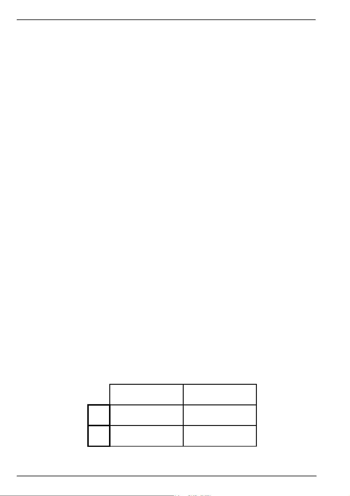
Cable diagrams represent cable shield in the following manner:
This shows the cable shield soldered to FG at both ends of the cable and
shows the shield running the full length of the cable. Please note that the
shield is treated as a totally separate wire.
4.1 Transient Protection on RS-422 Port
Power surges, or electrical transient voltages, can be induced into cabling by
nearby lightening strikes, electric motors, switches and the operation of heavy
industrial equipment, to name a few. The use of long cables, as with RS-422
connections, increases the exposure to transient voltages.
In an unprotected converter, a transient of the correct magnitude can destroy
the RS-422 transceiver chip on the RS-422 port. However, it is also possible
for certain transients to pass through a converter and therefore damage any
RS-232 attached equipment at the other end.
By using High Speed Transient Voltage Suppressors on the RS-422 port, the
A440 absorbs much of the transient energy on data lines and helps clamp
these surge voltages to a safe level, thereby protecting itself and other
connected equipment from the common damage due to transients.
Transient voltage suppressor diodes are used on each RS-422 line. Each
diode has a response time of less than 1 ps with power dissipation of 600Watts
for 1 ms and a steady state power dissipation rating of 5Watts.