ALFIX 6000 Series User manual

ALFIX MOBILE SCAFFOLD TOWER SerIeS 6000
INSTRUCTION
FOR ERECTION
AnD USE

2AuV ALFIX Mobile Scaffold Tower Series 6000
Instructions for Erection and UseGeneral Information
ALFIX Mobile Scaffold Towers 6001 – 6012
EN 1004 8/12 XXXD
Instructions for Erection and Use
EN 1298 -IM - de
Loadability:
600 kg, uniformly distributed
Platform dimensions:
2.60 x 1.40 m
Permissible load:
p = 2.00 kN/m2
on a loaded deck surface
(load class 3, DIN EN 1004)
Maximum permissible standing height:
12 m indoors (without wind load)
8 m outdoors (with wind load)
Access via vertical ladder

3
AuV ALFIX Mobile Scaffold Tower Series 6000
ALFIX Mobile Scaffold Tower Series 5000Contents
1. Schematic Drawing P. 4
2. Preface P. 5
3. Areas of Application P. 6
4. General Notes P. 7 - 11
5. Preparation of Erection P. 12
6. Assembly of the Erection Sections
6.1 Assembly of chassis P. 13 - 15
6.2 Assembly of working platform P. 16 - 19
6.3 Use of auxiliary assembly decks P. 20
7. Extensions
7.1 Stabiliser P. 21
7.2 Wall support P. 22
8. Ballasting
8.1 Indoors, central P. 23
8.2 Outdoors, central P. 23
8.3 Indoors, lateral P. 24
8.4 Outdoors, lateral P. 24
8.5 Indoors, central, with two stabilisers P. 25
8.6 Outdoors, central, with two stabilisers P. 25
8.7 Indoors, lateral, with one stabiliser P. 26
8.8 Outdoors, lateral, with one stabiliser P. 26
8.9 Indoors, lateral, with wall support P. 27
8.10 Outdoors, lateral, with wall support P. 27
9. Miscellaneous
9.1 Dismantling of mobile scaffold towers P. 28
9.2 Assembly of counterweights P. 28
9.3 Operating the castor wheels P. 29
9.4 Platform with hatch P. 30
9.5 Tips & tricks P. 31 - 32
10. Technical Data P. 33 - 34
11. Components Overview P. 35

4AuV ALFIX Mobile Scaffold Tower Series 6000
Instructions for Erection and Use1. Schematic Drawing
The three areas of erection
Side protection
Vertical frame
Platform with hatch-type access
Toeboard
Locking clip or hinged pin
Diagonal brace
Vertical frame
Diagonal brace
Side protection
Platform with hatch
Longitudinal ledger
Stabiliser
Diagonal brace
Vertical frame
Side protection for bracing
Counterweight
Platform without hatch
Rolling beam
Castor wheel
Working platformIntermediate levelChassis
Intermediate
deck
Platform
without hatch
Platform
without hatch

5
AuV ALFIX Mobile Scaffold Tower Series 6000
ALFIX Mobile Scaffold Tower Series 50002. Preface
Dear ALFIX Client,
With the ALFIX Mobile Scaffold Tower Series 6000, you have purchased a versatile and ro-
bust mobile tower (Mobile Working Platform).
In order to ensure safe working, its erection, use and dismantling must be carried out in
compliance with these “Instructions for Erection and Use”!
Please read this booklet carefully in advance. Take it with you prior to every single use. It
clearly explains all the required steps and security measures in the most appropriate order.
When working through all the pages, the schematic drawing, shown on the left, always
serves as an overview.
The types 6001-6012 correspond to all requirements of DIN EN 1004.
If you want to deviate from these Instructions for Erection and Use or if you have any ques-
tions concerning our mobile scaffold towers, please do not hesitate to call us. We are always
happy to help!
Yours ALFIX GmbH
ALFIX GmbH
Langhennersdorfer Str. 15
D-09603 Großschirma
Phone : +49 (0) 37328 / 800-0
Fax : +49 (0) 37328 / 800-80
Internet :
www.alfix-systems.com

6AuV ALFIX Mobile Scaffold Tower Series 6000
Instructions for Erection and Use3. Areas of Application
Prior to erecting your scaffold
There are two general areas of application:
Indoors, i.e. no wind effect (without wind load)
Outdoors, i.e. with the effect of wind (subject to wind load)
The representations, outlined below, are standard designs and are described in detail in
these Instructions for Erection and Use.
Other erection options must be agreed upon
with the manufacturer.
central lateral
lateral
with wall
support
central
with stabiliser
lateral
with stabiliser

7
AuV ALFIX Mobile Scaffold Tower Series 6000
ALFIX Mobile Scaffold Tower Series 50004. General Notes
Warranty
Scope and period of warranty are set forth in the manufacturer’s delivery and payment
conditions.
Intended use
The scaffolds listed in these Instructions for Erection and Use may only be used in accordance
with both the requirements of the EN 1004 standard and the structural design samples
specified herein.
Unintended use
The improper use of the scaffoldings specified in the present Instructions for Erection and
Use is considered to be an unintended use, as defined under the Product Safety Act [ProdSG]
(as amended 01/08/1997). This also applies to the disregard of the standards and guidelines
particularised in these Instructions for Erection and Use.
Overview of Mobile Scaffold Tower Series 6000 :
6001 6002 6003 6004 6005 6006
Working height [m] 3.00 3.30 4.80 5.90 6.75 7.90
Scaffold height [m] 1.40 2.40 3.95 5.05 5.95 7.00
Standing height [m] 1.00 1.30 2.80 3.90 4.75 5,90
6007 6008 6009 6010 6011 6012
Working height [m] 8.70 9.85 10.65 11.80 12.60 13.75
Scaffold height [m] 7.80 8.95 9.90 10.90 11.75 12.90
Standing height [m] 6.70 7.85 8.65 9.80 10.60 11.75

8AuV ALFIX Mobile Scaffold Tower Series 6000
Instructions for Erection and Use4. General Notes
Erection
1. The permissible load of the Mobile Working Platform is 2 kN/m² according to
DIN EN 12811-1, load class 3.
2. Prior to the erection and use of the Mobile Working Platform, the Instructions
for Erection and Use must be read carefully.
3. Only persons who are trained based on these Instructions for Erection and Use
may assemble, dismantle and use the Mobile Working Platform.
4. The assembly and dismantling must be performed by at least 2 persons. For
installation heights above 6 m, at least 3 persons are required.
5. The working platform’s maximum permissible height is 12 m. It is inadmissi-
ble to increase height through boxes, ladders or other means.
6. The Mobile Working Platform may not be operated using foreign parts from
other manufacturers. Only parts specified in the Instructions for Erection and
Use must be exclusively used for assembly.
7. Prior to erection, the following issues are to be checked:
• The ground must be level and of sufficient load-bearing capacity.
• There are no obstacles around the location of the mobile working plat-
form.
• Damaged, defective or non-system parts must be removed.
• The wind conditions must be suitable for assembly.
• The Instructions for Erection and Use must be available at the site of use.
8. For assembly and dismantling, the deck surfaces or intermediate levels must
be arranged so that the vertical distance between the deck/platform surfaces
does not exceed 2.10 m.
9. Upon assembly, both the completeness and the tight fit of all connections
must be checked.
10. If a deck surface on the first level is accessed, the distance from the ground to
the top edge of the deck must not exceed 60 cm.
11. The vertical maximum distance between the different deck surfaces must not
exceed 4.20 m.
Max. 4,20m
2 kN/m2
load class 3
DIN EN 12811-1
Max. 0,60m Max. 2,10m Max. 12m

9
AuV ALFIX Mobile Scaffold Tower Series 6000
ALFIX Mobile Scaffold Tower Series 50004. General Notes
Use
1. Assembly, dismantling and use of the Mobile Working Platform outside of en-
closed spaces is only permitted at wind forces below 6 Beaufort.
2. Horizontal and vertical load applications, which may cause the Mobile Work-
ing Platform to overturn, are to be avoided.
3. The Mobile Working Platform must not be lifted and displaced using a crane,
forklift or the like.
4. The Mobile Working Platform must not be moved, if persons or loose items are
situated on the decking.
5. In order to move the Mobile Working Platform, the wheel brake must be re-
leased.
6. Upon movement, the castors are to be locked once again using the wheel
brakes.
Dismantling
1. Dismantling of the Mobile Working Platform is to be carried out in reverse order.
Inspection, servicing, maintenance
1. Scaffolding components must be handled and transported carefully to avoid
damage.
2. All components must be checked for damage.
3. All moving parts must be checked for proper functioning and dirt.
4. Damaged components must be replaced, sent for repair to the manufacturer
or destroyed.
Caution :
• Any deviations from these Instructions for Erection and Use are not allowed!
• Structural changes to the Mobile Working Platform must only be carried out by the manufacturer!

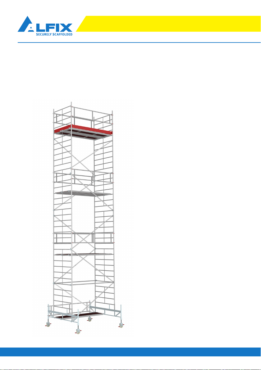
10 AuV ALFIX Mobile Scaffold Tower Series 6000
Instructions for Erection and Use4. General Notes
1. Erection, rebuilding and dismantling of the Mobile Working Platform must be
carried out in accordance with the Instructions for Erection and Use or upon
consultation with the manufacturer. The Instructions for Erection and Use
must always be available at the site of use! When handing over the Mobile
Working Platform to any third party, the Instructions for Erection and Use
must be forwarded to the user as well.
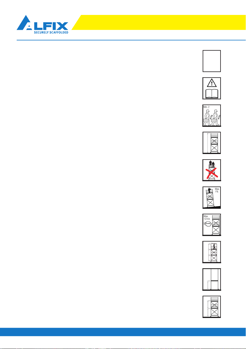
2. When working, a helmet and safety shoes must be worn.
3. When using the Mobile Working Platform outdoors or in open spaces at
wind forces exceeding six on the Beaufort scale (large branches in motion,
whistling in overhead power lines, difficulties to use an umbrella), the
platform is to be moved to a sheltered area or is to be secured against
overturning through appropriate measures (e.g. a compression-resistant
and tension-proof anchorage to a building structure) or is to be dismantled.
4. The scaffolding is to be placed perpendicular using the adjusting spindles.
5. Only original ALFIX counterweights may be used (no “equivalent weights”,
such as canisters with water, buckets of sand, etc.), the arrangement of
which is defined in these Instructions for Erection and Use.
6. The vertical frame joints are to be secured against accidental lifting using
locking clips or hinged pins.
7. Prior to using the scaffolding, its proper and correct erection must be
checked.
8. Access to the working platform shall only take place at the inside of the
scaffolding. The platforms with hatch-type access are to be alternately
arranged. The hatches are to be closed after climbing through.
9. Persons working on Mobile Scaffold Towers are not allowed to push
themselves against the side protection.
10. During movement, one must be certain that no people or loose objects are on
the Mobile Scaffold Tower.

11
AuV ALFIX Mobile Scaffold Tower Series 6000
ALFIX Mobile Scaffold Tower Series 50004. General Notes
11. Movement is allowed only on level and sufficiently load-bearing grounds
and only in longitudinal direction or by pivoting on its corner. The surface
slope shall not exceed 3 percent. In the event of single-sided wall support,
movement is only allowed parallel to the wall. Any impact is to be avoided.
Pay special attention to obstacles at high altitude! Upon movement, it must
be checked whether the Mobile Scaffold Tower is vertical and all castors have
ground contact. If not, the scaffolding must be realigned in accordance with
Item 6.1.9.
12. The safe distance to overhead lines is 5 metres. Here, the swinging-out of the
power cables and the motion space of the employees, including the materials to
be moved by them, must be taken into account. Smaller distances are possible
according to “Guidelines for handling working and safety scaffoldings BGI
663” of the Employer’s Liability Insurance Association for the Building Trade.
13. Upon movement, the castors must be locked by pushing down the brake
levers.
14. Attachment and use of lifting equipment to mobile working scaffolds is
prohibited.
15. Bridging two adjacent mobile working scaffolds or a mobile working scaffold
to a building is not permitted.
16. Jumping down to the deck surfaces or throwing objects at them is not allowed.
17. The scaffold parts may not be exposed to aggressive media. They may also
not be exposed to temperatures below -25 °C or above + 70 °C for extended
periods of time.
18. In the event of vehicular traffic in the vicinity of the Mobile Scaffold Tower, it is
to be secured and illuminated.

12 AuV ALFIX Mobile Scaffold Tower Series 6000
Instructions for Erection and Use5. Preparation of Erection
1. Determine the required standing height and select the appropriate Mobile
Scaffold Tower with the associated component requirements according to
page 35. Although components for a higher working platform are available,
the structure depends on the required height.
2. Prior to erection, it must be checked whether all parts (see tables on page
33) and tools required for the erection of the Mobile Scaffold Tower are avail-
able at the construction site. The same applies to eyebolts and plastic anchors
intended to be used for wall attachments. In addition, all components must
be checked for proper condition. Only undamaged original parts of the ALFIX
Mobile Scaffold Tower 6000 may be used. Damaged or defective parts must
be discarded.
3. For assembly and dismantling, at least two persons (with erection heights
above 6 m - three persons) and the following tools are required:
• Spirit level
• For standing heights above 4 m: rope with snap hook.
• Erection with tension-proof wall support: tool for setting the anchors
incl. mounting hardware (see Information of the anchor manufacturer)
4. Special features when erecting the Mobile Scaffold Towers 6001 and 6002:
• The castor wheels are to be directly plugged into the vertical frame
1.12 m (6001) and 1.96 m (6002) and connected to the side protec-
tion serving as bracing means.
• Subsequently, the platform is installed at the desired standing
height of 1 m (6001) or 1.30 m (6002).
• Access to the working level is performed using a stepladder.
• The ballasting, where appropriate, is set out on pages 23 to 27.

13
AuV ALFIX Mobile Scaffold Tower Series 6000
ALFIX Mobile Scaffold Tower Series 50006.1 Assembly of chassis
1. Assembly of rolling beam with castor wheels
• Insert two castor wheels each into the rolling beam.
Tighten the winged screws at the spindle nuts and
make sure that their threads engage the boreholes of
the rolling beam.
2. Lock the castor wheels
• by stepping down the brake levers or by putting the
castor wheel into the upright position.
3. Insert the vertical frames (1.12 m) into the rolling
beams centrally …
• and secure them with locking clips or hinged pins …
4. … or laterally
• and secure them with locking clips or hinged pins ...

14 AuV ALFIX Mobile Scaffold Tower Series 6000
Instructions for Erection and Use6.1 Assembly of chassis
5. Arrange the vertical frames in the upright position
and connect them by inserting the side protection
6. … or, in the event of lateral erection: connect the
rolling beams at the vertical frames’ side with the
side protection.
• For the connection of couplers, see also pages 31-32
“Tips & Tricks”
7. Approximately adjusting the chassis
• To compensate for larger unevenness, rotate the
spindle nuts at the height-adjustable castors, which
are to be relieved by lifting up the rolling beam, to
the approximately required height.
8. Insert the platform without hatch into the rolling
beam
• To install the platform, see also page 31-32 “Tips &
Tricks”

15
AuV ALFIX Mobile Scaffold Tower Series 6000
ALFIX Mobile Scaffold Tower Series 50006.1 Assembly of chassis
9. Aligning the chassis
• Align the chassis horizontally and vertically in
longitudinal and transverse directions using a spirit
level (tolerance ± 1%). Subsequently, tighten the
winged screws at the spindle nuts.
10. Suspending the counterweights
• Attach all counterweights required for the final
erection!
• The distribution of counterweights is described
on pages 23 to 27. On page 28, you will find the
corresponding assembly instructions.
Exemplary suspended counterweights
for Mobile Scaffold Tower 6005
The further erection of types 6003 and 6004
is to be carried out according to
“6.2 Assembly of Working Platform”.

16 AuV ALFIX Mobile Scaffold Tower Series 6000
Instructions for Erection and Use6.2 Assembly of working platform
1. Fixing the assembly deck
• For assembly and dismantling, the deck surfaces or
intermediate platforms must be arranged so that
the vertical distance between the deck/platform
surfaces does not exceed 2.10 m.
2. Inserting the vertical frames 1.96 m
• Secure them with locking clips. See p. 31-32 “Tips
& Tricks”
3. Bracing with diagonal braces
• The diagonal braces must be alternately hooked into
the lower tube of the rolling beam.
• To install the diagonal braces, please refer to pages
31-32 “Tips & Tricks”
4. Fixing a platform with hatch-type access
• With types 6003 and 6005, the platform is to be
suspended in the eighth rung above the first deck.
• With types 6004 and 6006 to 6012, the platform
serves as an assembly aid and must not be hooked
in at heights exceeding the seventh rung above the
first deck. It is necessary to install one platform with
hatch-type access and one platform without hatch-
type access. If the platforms will not remain at this
height, longitudinal ledgers are to be additionally
arranged.

17
AuV ALFIX Mobile Scaffold Tower Series 6000
ALFIX Mobile Scaffold Tower Series 50006.2 Assembly of working platform
5. Assembly of side protection
• Open the access hatch and sit on the opened hatch.
The legs have to be stretched through the opening
and rest on the rungs of the vertical frame.
• Do not enter the platform unless both side protection
components are hooked in!
• Raise the side protection up and attach it first on one
side. Check whether the claw coupler is released.
Then pivot the other end to the vertical frame and
latch it (cf. Item 9.5.5). Remain seated during this
process. Side protection components are always
installed from the inside between the second and
fourth rung!
• Repeatthis procedure for the second side protection.
• Now, you can enter the decking and close the hatch.

18 AuV ALFIX Mobile Scaffold Tower Series 6000
Instructions for Erection and Use6.2 Assembly of working platform
6. ... further vertical frames
• cf. Item 6.2.2
7. Bracing with diagonal braces
• Hook the diagonal braces into the same rungs
where the “last”diagonal braces are attached, or,
as described in Item 6.2.3, hook them into the lower
tube of the rolling beam. With certain mobile scaffold
towers (see erection sketches attached), one rung is
to be left between the diagonal braces.
8. Suspending a platform with hatch-type access at
heights not exceeding the seventh rung above the
last platform
• The platforms must be alternately suspended !

19
AuV ALFIX Mobile Scaffold Tower Series 6000
ALFIX Mobile Scaffold Tower Series 50006.2 Assembly of working platform
9. Suspending the uppermost working platform
• The platform with hatch-type access must be
alternately suspended with reference to the last
attached platform. Its installation height must not
exceed the fifth last rung.
• To install the platform, see also page 31-32 “Tips &
Tricks”.
• On the working level, the intermediate platform is to
be suspended in the centre between the platforms
with and without hatch.
10. Suspending the side protection components
• The side protection above the uppermost platform
must be installed from the inside, above the second
and below the fourth rung.
• For assembling the side protections, please refer
also to page 17 (cf. Item 6.2.5)
11. Installing and inserting the toeboards
• First, lean the two end toeboards against the frames.
The attachments must be directed to the outside!
Then insert the longitudinal toeboards into the slots
provided by the end toeboards.

20 AuV ALFIX Mobile Scaffold Tower Series 6000
Instructions for Erection and Use
6.3 Use of auxiliary assembly decks
1. Unhook the side protection components referred
to under Item 6.2.5 and re-install them between
second and fourth rung above the uppermost
platform.
• The platforms and side protections remain within the
Mobile Scaffold Tower at a height distance of up to
4 m. The assembly decks in between are dismantled
and used again at a higher level.
2. Dismantling of guardrails
• Loosen the side protection components on the
opposite end of the access hatch.
• Similar to the assembly process, sit on the bottom
with the legs stretched through the opening and
resting on the rungs of the vertical frame.
• Then, unlock the two guardrail ledgers situated in
the front and pass the released, dismantled side
protection upwards in order to continue assembling
or ...
• ..., for the purpose of dismantling, downwards.
3. Dismantling of platforms
• After removing the guardrail, climb down to the
next intermediate deck and close the hatch of the
assembly deck.
• Then, you can pass the platforms upwards or
downwards.
• Installation of the platforms and attachment of the
guardrail, cf. Item 6.2.4 or 6.2.5.
• With the assembly level, the distance between two intermediate storeys is bridged,
ensuring that during assembly and dismantling the 2.10 m distance willnot be exceeded.
• An assembly level is formed from a platform with hatch and a platform without hatch,
and two side protection guardrails.
• An assembly level can be removed after the erection of the intermediate storey and can
be used again further above.
This manual suits for next models
12
Table of contents
Other ALFIX Construction Equipment manuals