ALFRA 03855 AHP-M User manual

Bedienungsanleitung / Operation manual /
Mode d‘emploi
ALFRA Hydraulikpumpe AHP-M
Elektrische Hydraulikpumpe 03855 und 23189
Electric Hydraulic Pump 03855 and 23189
Pompe hydraulique électrique 03855 et 23189

2
Inhaltsverzeichnis
Sicherheitshinweise, Bestimmungsgemäße Verwendung 3
Technische Daten, Verfügbares Zubehör 4
Gerätebeschreibung 5
Inbetriebnahme 6
Positionierung der Pumpe während des Betriebes, Ölwechsel 7
Wartung und Inspektion 8
Fehleranalyse 9
EG-Konformitätserklärung 11
Explosionszeichnung und Ersatzteilliste 30
Vor Inbetriebnahme Bedienungsanleitung lesen und aufbewahren!
Contents
Safety Instructions, Specified Conditions of Use 12
Technical Data, Available Accessories 13
Description 14
Start-up 15
Positioning the Pump during Operation, Oil Change 16
Maintenance and Inspection 17
Troubleshooting 18
EC Declaration of Conformity 20
Exploded Drawing and Spare Parts List 30
Before use read and save these instructions!
Table des matières
Consignes de sécurité, Utilisation conforme à l’usage prévu 21
Données techniques, Accessoires disponibles 22
Description de l’appareil 23
Mise en service 24
Positionnement de la pompe pendant l’opération, Vidange 25
Maintenance et inspection 26
Analyse des défauts 27
Déclaration CE de conformité 29
Vue éclatée, Liste des pièces de rechange 30
À lire avant la mise en service puis à conserver!

3
Sehr geehrter Kunde,
vielen Dank, dass Sie sich für ein ALFRA-Produkt entschieden haben. Lesen Sie diese Bedienungsanleitung vor
der ersten Verwendung Ihres neuen Gerätes aufmerksam durch und heben Sie sie zusammen mit der beigelegten
Product Control Card auf, um bei Bedarf darin nachschlagen zu können.
Sicherheitshinweise
Beim Arbeiten mit Hochdruck-Hydraulikpumpen können unsachgemäße Handhabung und/oder schlechte Wartung
die Maschine beschädigen und schwere Verletzungen verursachen. Beachten Sie daher alle folgenden
Sicherheitshinweise und wenden Sie sich bei Fragen an unser Service-Team.
Achtung:
Vorsicht beim Umgang mit Hydrauliköl. Bei längerem Betrieb kann sich das Öl stark erhitzen.
Es besteht Verletzungsgefahr!
Um die Lebensdauer der Werkzeuge zu verlängern, sollten diese nicht unter vollem Druck auf
den Block oder bis zum Anschlag gefahren werden.
Immer…
mit der Belüftungsschraube arbeiten, damit der Tank während des Pumpens “atmen“ kann
mit der abdichtenden Verschlussschraube transportieren, damit das Hydrauliköl nicht ausläuft
für ausreichend Frischluftzufuhr sorgen
elektrische und hydraulische Anschlussleitungen auf Beschädigung überprüfen
Netzspannung passend zur Maschine wählen
den Anweisungen der Bedienungsanleitung folgen
neue Nutzer in den sicheren Gebrauch der Maschine einweisen
mit Schutzbrille und Ohrenschutz arbeiten
die lokalen, landesspezifischen Richtlinien befolgen
trocken und in gut gelüfteten Räumen lagern
Niemals…
die Maschine verändern oder Hinweisschilder entfernen
unbekannte oder beschädigte Werkzeuge verwenden
die Pumpe bei Beschädigung oder bei fehlenden Teilen verwenden
unter Druck stehende Kupplungen öffnen
unverbundene Schlauchkupplungen unter Druck setzen
die Hydraulikpumpe ohne fachgerechte Einweisung benutzen
benutzen, sofern diese Bedienungsanleitung nicht vollständig gelesen und verstanden wurde
die Hydraulikpumpe bei Temperaturen über 45°C (113°F) lagern oder betreiben
die Maschine unbeaufsichtigt in Betrieb lassen
mit ätzenden Stoffen in Verbindung bringen
in explosionsgefährdeten Räumen verwenden
Bestimmungsgemäße Verwendung
Die ALFRA Hydraulikpumpe AHP-M ist eine einfachwirkende Radialkolbenpumpe und dient der Verwendung von
einfachwirkenden Hydraulikwerkzeugen mit automatischer Ölrückführung und ausreichender Druckstabilität. Die
AHP-Pumpe mit der Artikelnummer 03855 ist nur für die Bearbeitung von Kupfer bestimmt. Für die Verwendung
mit unseren APS-Stanzbügeln benutzen Sie die Pumpe mit der Artikelnummer 23189.

4
Technische Daten
Art.-Nr. und Bezeichnung:
03855 AHP-M Hydraulikpumpe
23189 AHP-M Hydraulikpumpe
Leistungsaufnahme:
1300 Watt
Lastdrehzahl:
28601-min
Spannung:
230 V 50 Hz
Imax @700 Bar
5,7 A
Hydraulisches Medium:
HLP 46 Öl
Max. Druck:
700 Bar
10150 psi
Max. Fördervolumen:
1,1 l/min
0,29 gal/min
Füllvolumen des Tanks:
3,0 l
0,79 gal
Arbeitsvolumen:
2,2 l
0,58 gal
Gewicht:
29 kg
64 lbs
Geräuschemission:
92 dB(A) @ 300 mm Abstand vom Motor
Vibration am Handgriff:
AC=3,5 mm/s² und VC=3,2 mm/s
Verfügbares Zubehör Art.-Nr.
Verlängerungsschlauch auf Anfrage möglich
ALFRA Service-Boy-Transportwagen 23160
Ersatz-Hydrauliköl HLP46 (5 Liter) 3000
Fußschalter, 2-pedalig (nur für AHP-M 03855) 03866
Fußschalter, 3-pedalig (nur für AHP-M 03855) 03863
Handschalter (für AHP-S und AHP-M 03855) 03859

5
Gerätebeschreibung
Die einfachwirkende Hydraulikpumpe ALFRA AHP-M ist eine einstufige Radialkolbenpumpe, die mit einem
leistungsstarken Elektromotor (1) ausgestattet ist und mit drei Pumpenelementen beste Förderleistungen erzielt.
An beiden Seiten der Pumpe befinden sich zwei stabile Tragegriffe (2), um die die elektrischen Zuleitungen
gewickelt werden können.
Auf der Vorderseite befinden sich das Netzkabel (4), der Anschluss für die Steuerleitung (6) sowie das Typen-
schild (7). Über den Hauptschalter (5) kann die Pumpe in den Bereitschaftsmodus gesetzt und anschließend mit
den Steuersignalen des Handschalters aktiviert werden. Der Ölstand im Inneren des Tanks lässt sich jederzeit über
das Sichtfenster (8) neben den Tragegriffen prüfen. Der Handschalter kann entweder an der Seite oder oben auf
dem Gehäuse an einem der beiden schwarzen Clips (9) befestigt werden. Der verbaute Asynchronmotor ist
besonders laufruhig und verfügt über einen Betriebskondensator (12). Das integrierte Magnetventil (14) steuert den
erzeugten Ölstrom und hält den Druck bei der Pausenfunktion im Werkzeug. Sollte der Arbeitsdruck im Werkzeug
über den eingestellten maximalen Druck der Pumpe steigen, öffnet sich das Überdruckventil (13) und leitet den
Ölstrom in den Tank der Pumpe zurück. Die Tanköffnung (10) wird im Betrieb mit der luftdurchlässigen
Belüftungsschraube und für den Transport mit der dichtenden Verschlussschraube (11) verschlossen.
1) Antriebsmotor
11) Verschlussschraube
2) Tragegriffe
12) Betriebskondensator
3) Anschluss Ölleitung
13) Überdruckventil
4) Netzkabel
14) Magnetventil
5) Netzschalter
15) Steuerleiterplatte
6) Anschluss Steuerleitung (5-polig)
7) Typenschild
8) Sichtfenster für Ölstand
9) Befestigungsclip für Handschalter
10) Tanköffnung mit Belüftungsschraube

6
Inbetriebnahme
Sie erhalten eine vollständig montierte Hydraulikpumpe sowie eine detaillierte Bedienungsanleitung. Bitte prüfen
Sie bei Erhalt der Ware deren Zustand auf mögliche Transportschäden und den Lieferumfang auf Vollständigkeit.
Wenden Sie sich bei Problemen bitte umgehend an den Hersteller oder Ihren Händler.
Vor dem ersten Gebrauch unbedingt die Bedienungsanleitung lesen!
1. Prüfen Sie den Ölstand durch die seitlichen Sichtfenster und füllen Sie bei Bedarf neues Hydrauliköl HLP 46
nach.
Hinweis:
Der Ölstand der ALFRA AHP-Hydraulikpumpe sollte sich im Normalzustand zwischen den Markierungen
„Min“ -„Max“ auf der Seite des Pumpengehäuses befinden. Damit ist gewährleistet, dass bei der
Verwendung der angeschlossenen Werkzeuge ausreichend Hydrauliköl zur Verfügung steht, um den
Zylinder zu füllen und zu verhindern, dass die Pumpe trocken läuft.
2. Kabel und Stecker auf Beschädigung prüfen, danach den Netzstecker einstecken.
3. Hydraulikschlauch auf Quetschungen oder andere Beschädigungen überprüfen und mit der Schnellkupplung
der Pumpe und des Werkzeugs verbinden.
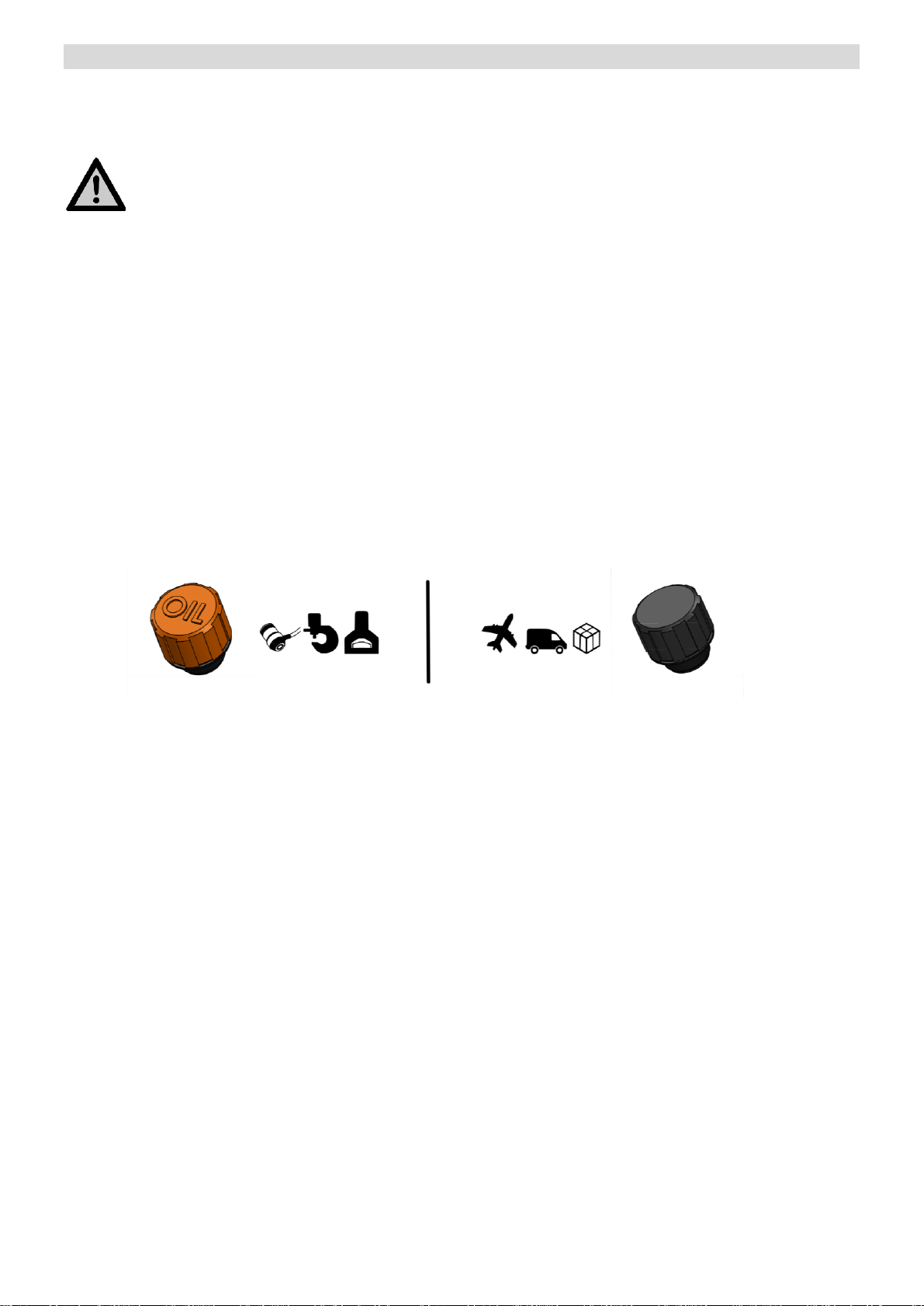
4. Vor der ersten Verwendung unbedingt die abdichtende Verschlussschraube (schwarz) an der Tanköffnung
durch die luftdurchlässige Belüftungsschraube (orange) ersetzen, damit während der Arbeit Luft in den Öltank
strömen kann.
5. Die Steuerleitung des Werkzeugs, der Fernbedienung oder des Fußschalters an die 5-polige Flanschdose
anschließen.
6. Netzschalter auf (I) stellen, um die Pumpe einzuschalten und in den Bereitschaftsmodus zu versetzen.
7. Das gewünschte Material im Werkzeug positionieren und je nach Bearbeitung auf eine mittige Positionierung
achten.
Beachten Sie stets die Angaben der Bedienungsanleitung sowie die Verwendungsdaten und
Besonderheiten des angeschlossenen Werkzeugs!
Verwenden Sie keine Werkzeuge, die Schäden aufweisen oder mit deren Umgang Sie nicht vertraut sind!
8. Durch Betätigung des Startschalters am Werkzeug, dem Handschalter oder dem Fußschalter werden der
Pumpenmotor und das Magnetventil aktiviert, sodass der Ölstrom ins Werkzeug freigegeben ist.
Je nach Steuereinheit oder Werkzeug kann der Bearbeitungsvorgang mit einer Pausenfunktion
unterbrochen werden. Hierbei wird der Motor zwar angehalten, doch das Magnetventil bleibt aktiviert,
sodass das Werkzeug nicht zurückfährt und der Druck im System bestehen bleibt.
9. Nach dem Arbeitsvorgang den Stoppschalter betätigen, um die Pumpe und das Magnetventil zu deaktivieren.
Das Öl kann nun vom Werkzeug in den Tank der Pumpe zurückströmen und das Werkzeug fährt in seine
Ausgangsposition zurück.
10.Um die Pumpe auszuschalten, den Netzschalter auf (O) stellen. Vor dem Transport die Belüftungsschraube
entfernen und die Tanköffnung mit der Verschlussschraube verschließen, um ein Auslaufen der
Hydraulikflüssigkeit zu vermeiden.

7
Positionierung der Pumpe während des Betriebes
Der Öltank der AHP-Pumpen ist während des Betriebes durch die Belüftungsschraube verschlossen und ist somit
nicht abgedichtet. Um zu vermeiden, dass das Hydrauliköl aus- oder überläuft, darf die Pumpe nicht in
übermäßiger Schräglage verwendet werden. Die seitlichen Sichtfenster am Pumpengehäuse dienen der
Sichtkontrolle.
Nach einiger Zeit intensiver Nutzung ist die Bildung von Schaum auf der Öloberfläche möglich. Bei übermäßiger
Schräglage der Pumpe kann Schaum durch die Belüftungsschraube an der Tanköffnung austreten. Achten Sie
deshalb stets auf eine möglichst horizontale Positionierung der Pumpe.
Ölwechsel
Mit regelmäßiger Wartung Ihrer ALFRA AHP-M Hydraulikpumpe können Sie die Standzeit der Dichtungen und
beweglichen Teile verlängern. Bei häufiger Nutzung der Hydraulikpumpe muss das Hydrauliköl komplett erneuert
werden, um Ablagerungen und kleine Schwebstoffe aus dem Tank zu entfernen. Der erste Ölwechsel sollte nach
etwa 50 Betriebsstunden, danach einmal jährlich durchgeführt werden.
Schutzbrille und Ohrenschutz tragen!
1. Den Netzstecker ziehen.
2. Die Verschlussschraube entfernen und die 1/2“ Gewindetülle (2) mit dem Silikonschlauch (1) in die
Tanköffnung schrauben.
3. Die Pumpe schräg nach vorne kippen und das Öl in einen Auffangbehälter laufen lassen.
4. Nun die Pumpe wieder horizontal aufstellen und die Gewindetülle mit dem Silikonschlauch entfernen. Den
Tank bis zur Markierung „Max“ mit Hydrauliköl HLP 46 auffüllen (etwa 3 Liter).
Vor der ersten Verwendung von Werkzeugen und Zylindern muss die Pumpe entlüftet werden!

8
5. Um die Pumpe zu entlüften, das Kupplungsstück an der Endkupplung des Schlauchpaketes aufstecken.
6. Die Pumpe aktivieren und den geförderten Ölstrom in den geöffneten Tank zurückfließen lassen.
Vorsichtiges Kippen und Schrägstellen der Hydraulikpumpe erleichtert den Abbau eingeschlossener
Luftpolster.
7. Das Aggregat für etwa 60-120 Sekunden Öl fördern lassen. Sobald der Ölstrom gleichmäßig und ohne
Luftblasen oder Unterbrechungen aus dem Schlauch strömt, ist die Pumpe ausreichend entlüftet und für
die weitere Verwendung bereit.
8. Das Kupplungsstück vom Schlauch entfernen.
9. Den Ölstand abschließend prüfen. Zur weiteren Verwendung der Pumpe die Tanköffnung mit der
Belüftungsschraube, andernfalls mit der Verschlussschraube verschließen.
Hydrauliköle sind umweltschädlich und müssen entsprechend den lokalen Normen und
Vorschriften fachgerecht entsorgt werden.
Wartung und Inspektion
Der Nutzer ist verpflichtet, die Hydraulikpumpe gemäß den Angaben in der Bedienungsanleitung und entsprechend
den landesspezifischen Normen und Regeln zu warten und zu pflegen.
Die Wartungsintervalle werden nach der empfohlenen Häufigkeit der Durchführung eingeteilt.
Vor jeglichen Pflege- und Reparaturarbeiten immer zuerst den Netzstecker ziehen!
Vor jeder Benutzung…
Pumpe und Schläuche visuell auf Beschädigung prüfen
den korrekten, festen Sitz der Kupplungen überprüfen
Anschlussleitungen auf Beschädigung kontrollieren
Wöchentlich…
den Motorraum von außen mit trockener Druckluft ausblasen
Monatlich…
Markierungen und Hinweisschilder der Pumpe auf Lesbarkeit und Beschädigung prüfen und
bei Bedarf ersetzen
Ölstand überprüfen und bei Bedarf Hydrauliköl HLP 46 bis „-Max“ nachfüllen
Jährlich…
kompletter Ölwechsel mit 3 Litern Hydrauliköl HLP46
Warten, prüfen und reparieren dürfen nur Elektrofachkräfte nach den im jeweiligen Land gültigen Vorschriften.
Verwenden Sie nur Original-ALFRA-Ersatzteile.
Eine ausführliche Ersatzteilübersicht finden Sie am Ende dieser Bedienungsanleitung.

9
Fehleranalyse
Warten, prüfen und reparieren dürfen nur Elektrofachkräfte nach den im jeweiligen Land gültigen Vorschriften.
Fehler
Kontrolle
Ursache
Behebung
Hauptschalter leuchtet
beim Einschalten nicht
Stromversorgung und
Netzleitung kontrollieren
Netzleitung nicht oder
fehlerhaft eingesteckt
Elektroanschluss durch
eine Elektrofachkraft
überprüfen und reparieren
lassen
Kabelbruch oder
Netzleitung beschädigt
Sicherung hat durch
Fehlerstrom ausgelöst
Motor läuft nicht an oder
bewegt sich nicht
Ist die Steuerleitung des
Werkzeugs
angeschlossen?
Steuerleitung nicht oder
fehlerhaft eingesteckt
Elektroanschluss durch
eine Elektrofachkraft
überprüfen und reparieren
lassen
Ist das passende
Werkzeug mit der
richtigen Ansteuerung
gewählt worden?
Pin-Belegung und Taster
des Werkzeugs müssen
zur Pumpe passen
Kompatibles Werkzeug
wählen oder Rücksprache
mit dem Hersteller halten
Ist der passende Hand-
oder Fußschalter gewählt
worden?
Pin-Belegung und Taster
müssen zur Pumpe
passen
Kompatiblen Hand- oder
Fußschalter wählen oder
Rücksprache mit dem
Hersteller halten
Hat die elektrische
Absicherung der
Stromversorgung
ausgelöst?
Stromversorgung ist nicht
für den max. Strombedarf
des Elektromotors
ausgelegt
Motor an eine andere
geeignete Strom-
versorgung anschließen
Elektrische Absicherung
ist nicht ausreichend
dimensioniert
Andere Absicherung
Verwenden, Leitungs-
schutzschalter 16A Typ B
Funktioniert die
Steuerleiterplatte korrekt?
Liegt Netzspannung am
Motorkabel oder dem
Motorklemmkasten an?
Steuerleiterplatte defekt
oder falsch angeschlossen
Elektroanschluss durch
eine Elektrofachkraft
überprüfen und reparieren
lassen
Bauteil austauschen oder
Reparatur beim Hersteller
/ Fachhändler
Kann das Lüfterrad des
Motors bewegt werden?
Unbedingt den
Netzstecker ziehen!
Motor durch Überlast,
Verschmutzung oder
Fremdkörper mechanisch
blockiert
Bauteil austauschen oder
Reparatur beim Hersteller
/ Fachhändler
Leistungsschütz zieht
nicht an
Schütz defekt, Kontakte
eingebrannt
Bauteil austauschen oder
Reparatur beim Hersteller
/ Fachhändler
Anlaufstrombegrenzung
an der Seite des Motors
defekt bzw. nicht mehr
elektrisch leitend (ca. 5
Ohmen Wiederstand bei
25°C Körpertemperatur
der IRC-Thermistoren)
IRC-Thermistoren durch
Überlast oder Abnutzung
defekt
Bauteil austauschen oder
Reparatur beim Hersteller
/ Fachhändler
Elektromotor dreht nur
leicht oder bringt nicht mit
die volle Leistung
Wird ein Verlängerungs-
kabel oder eine
Kabeltrommel zum
Anschluss an die
Stromversorgung
verwendet?
Kabel ist nicht vollständig
abgerollt
Kabel vollständig
abrollen
Leitungsverlust
(elektrischer Widerstand
zu hoch)
Kürzeres Verlängerungs-
kabel oder Kabel mit
Größerem Leitungs-
querschnitt verwenden
Nur AHP-L

10
Ist das verwendete
Werkzeug in der
Endposition?
Pumpe kann nur begrenzt
gegen Gegendruck
anfahren (ca. 200-300
Bar)
Werkzeug zurück fahren
lassen oder das
hydraulische System bzw.
das Werkzeug entlasten
Steht das Werkzeug unter
hohem hydraulischem
Druck?
Anlauf-oder
Betriebskondensator
überprüfen
Anlauf-oder
Betriebskondensator
defekt
Bauteil austauschen oder
Reparatur beim Hersteller
/ Fachhändler
Angeschlossenes
Werkzeug bewegt sich
nicht
Ist die Stromversorgung
gegeben?
Siehe oben
Siehe oben
Bewegt sich der Motor?
Sind die
Hydraulikkupplungen
korrekt an geschlossen?
Schnellkupplungen sind
nicht vollständig
eingerastet oder die
Kupplungsverschraubung
ist nicht komplett
zusammengedreht.
Hydraulikkupplungen sind
selbstverschließend und
öffnen nur, wenn sie
komplett bis Anschlag
eingesteckt oder
eingeschraubt sind.
Kupplung bis Anschlag
einstecken oder
einschrauben
Hydraulikkupplung ist
verdreckt und schließt
nicht korrekt
Kupplung reinigen und bis
Anschlag einstecken /
einschrauben
Bauteil austauschen oder
Reparatur beim Hersteller
/ Fachhändler
Zieht das Magnetventil an
und leitet den Ölstrom
zum Werkzeug?
Fest auf die Kunststoff-
kappe des Ventils drücken
und eine leichte
Bewegung erfühlen
Magnetventil defekt oder
überhitzt
Bauteil austauschen oder
Reparatur beim Hersteller
/ Fachhändler
Spannungsversorgung
des Magnetventils
überprüfen
Falsches Steuersignal
oder Leiterplatte defekt
Elektroanschluss durch
eine Elektrofachkraft
überprüfen und reparieren
lassen
Bauteil austauschen oder
Reparatur beim Hersteller
/ Fachhändler
Werkzeug fährt nicht voll
aus oder baut keinen
Druck auf
Ist die Belüftungsschraube
am Tank montiert?
Keine ausreichende
Belüftung des Tanks
Belüftungsschraube in
Tanköffnung eindrehen.
Ölfüllstand kontrollieren
Zu wenig Öl im Tank
Ausreichend Hydrauliköl
HLP46 nachfüllen
Kein voller Druckaufbau
am Werkzeug
Luft im System
Pumpe, Schläuche und
Werkzeug entlüften
Anderes Werkzeug
anschließen und Funktion
überprüfen
Werkzeug defekt
Werkzeug austauschen
oder reparieren
Schäumt das Öl und ist
genügend Öl im Tank?
Ansaugfilter verschmutz
oder verstopft
Bauteil austauschen oder
Reparatur beim Hersteller
/ Fachhändler

11
Markus A. Döring
(Geschäftsführer)
EG-Konformitätserklärung
Hiermit erklären wir,
Alfra GmbH
2. Industriestr. 10
68766 Hockenheim
dass die Hydraulikpumpe
ALFRA AHP-M
folgenden Richtlinien entspricht:
Maschinenrichtlinie: 2006/42/EG
Niederspannungsrichtlinie: 2006/95/EG
Elektromagnetische Verträglichkeit (EMV): 2004/108/EG
RoHs-Richtlinie: 2011/65/EU
Folgende Normen oder normative Dokumente wurden angewandt:
Maschinenrichtlinie:
EN 61029-1:2009
Niederspannungsrichtlinie:
EN 60204-1:2006+A1:2009
EN 60034-1:2010
EN 60034-5:2001+A1:2007
EMV- Richtlinie:
EN 55014-1:2006+A1:2009+A2:2011
EN 55014-2:1997+A1:2001+A2:2008
EN 61000-3-2:2006+A1:2009+A2:2009
EN 61000-3-3:2008
RoHs-Richtlinie:
EN 50581:2012
Bevollmächtigt für die Zusammenstellung der Unterlagen:
Alfra GmbH
2. Industriestr. 10
68766 Hockenheim
Hockenheim, 03.04.2017

12
Dear customer,
Thank you for purchasing an ALFRA product. Please read these operation instructions closely before using your
device for the first time and keep them along with the enclosed Product Control Card for later reference.
Safety Instructions
Danger can occur when working with high pressure hydraulic pumps due to improper handling and/or poor
maintenance, which may lead to the destruction of the device and to severe physical injuries. Please observe all
safety instructions of this operation manual and contact our Service Team if you have any questions.
Important:
Caution! Hydraulic oil may become hot in the event of extended use. Risk of injury!
Do not move tools under full pressure to the block or as far as they will go. Failure to do so can
shorten the lifecycle of your tool.
Always...
use the ventilation bolt to let the oil tank breathe
install the sealing plug bolt for transport. Failure to do so can cause oil leakage.
provide sufficient ventilation
check electric and hydraulic connection cables for damage
make sure the mains voltage matches the machine
follow the instructions in these operation instructions
familiarize new users with the safe use of this machine
wear safety goggles and ear protection during work
observe local, country-specific guidelines
store in a dry and well-ventilated place
Never...
modify this machine or remove signs
use unknown or damaged tools
use this pump when damaged or when parts are missing
open couplings under pressure
put non-connected hose couplings under pressure
use this hydraulic pump without having been properly instructed
operate this machine without having read and understood the complete operating manual
store or operate this hydraulic pump at temperatures above 45°C (113°F)
leave this machine running unsupervised
allow the machine to come into contact with corrosive materials
use in an environment where there is a risk of explosion
Specified Conditions of Use
The ALFRA AHP-M hydraulic pump is a single-acting radial piston pump and is destined to be used for single-
acting hydraulic tools with automatic oil return and sufficient pressure stability. The AHP pump with product code
03855 may only be used for working with copper. When working with our Punching Units APS use AHP-M with
product code 23189.

13
Technical Data
Prod.-No. and description:
03855 AHP-M Hydraulic Pump
23189 AHP-M Hydraulic Pump
Input:
1300 Watt
Load rpm:
2860 1-min
Voltage:
230 V 50 Hz
Imax @700 bar:
5.7 A
Hydraulic medium:
HLP 46 oil
Max. pressure:
700 bar
10150 psi
Max. delivery volume:
1.1 l/min
0.29 gal/min
Tank volume:
3.0 l
0.79 gal
Operating volume:
2.2 l
0.58 gal
Weight:
29 kg
64 lbs
Noise emission:
92 dB(A) @ 300 mm distance
from the motor
Vibration on the handle:
AC=3.5 mm/s² and VC=3.2 mm/s
Available Accessories Prod.-No.
Extension hose On request
ALFRA Service-Boy transport cart 23160
Hydraulic oil HLP 46 (5 l) 3000
Foot switch with two pedals (only for AHP-M 03855) 03866
Foot switch with three pedals (only for AHP-M 03855) 03863
Hand switch (for AHP-S and AHP-M 03855) 03859

14
Description
The single-acting hydraulic pump ALFRA AHP-M is a radial piston pump equipped with a high performance electric
motor (1) and achieves optimum delivery volume with three pump elements. Two stable carrying handles (2) can
be found on both sides of the pump around which the electric feed lines can be wound if necessary.
The mains (4), the connection for the commanding feed (6) and the nameplate (7) are located on the front side.
The pump is put into standby by pressing the main switch (5) and can then be activated via the commanding
signals of the hand switch. A window (8) next to the carrying handles allows the operator to check the oil level
inside the tank at any time. The hand switch can be attached to one of the two black clips (9) on the side or on the
top of the housing. The incorporated asynchronous motor is smooth-running and equipped with an operating
capacitor (12). The integrated magnetic valve (14) controls the generated oil flow and maintains the pressure within
the tool when the pause function is activated. If the working pressure inside the tool exceeds the maximum
regulated pressure of the pump, the excess pressure valve (13) opens and guides the oil back into the pump tank.
The oil tank vent (10) is closed by means of the air-pervious ventilation bolt during operation and the sealing plug
bolt (11) during transport.
1) Motor
11) Plug bolt
2) Carrying handles
12) Operating capacitor
3) Connection for oil feed
13) Excess pressure valve
4) Mains
14) Magnetic valve
5) Mains switch
15) Printed circuit board
6) Connection for commanding feed (five pole)
7) Nameplate
8) Window for oil level
9) Attachment clip for hand switch
10) Oil tank vent with ventilation screw

15
Start-up
You receive a completely assembled hydraulic pump and a detailed operating manual. Please check the condition
of the goods on receipt for any transport damage, and make sure the delivery is complete. Otherwise contact the
manufacturer or distributor immediately.
Always read the operating manual before using this device for the first time!
1. Check the oil level trough the lateral window and refill new oil (HPL 46) if necessary.
Note:
The oil level of the AHP-M should be between the "Min" - "Max" markings on the side of the pump housing
during standby mode. This ensures that there is sufficient oil during use of the connected tools to fill the
cylinder and to prevent the pump from running dry.
2. Check the cable and connector for damages, and then plug in the power plug.
3. Check the hydraulic hose for pinches or any other damage and connect it to the quick coupling of the pump and
the tool.
4. Before using the pump for the first time be sure to replace the sealing plug bolt (black) on top of the tank with
the air-pervious ventilation bolt (orange). This will allow the air to flow through the oil tank.
5. Connect the control cable of the tool, hand switch or foot switch to the 5-pole flange socket.
6. Turn the main switch into the position (I) to switch the pump on and to put it into standby mode.
7. Position the desired material in the tool and ensure a central position according to your application.
Be sure to observe the operation and safety instructions of the connected tool.
Do not use any tool if it is damaged or if you are not familiar with its use.
8. Push the start button on the tool, hand switch or food switch to activate the pump motor and magnetic valve.
The oil flow is released into the tool.
Depending on the control unit or tool, the operator can use the pause function to interrupt the operation.
Although the motor will stop during the pause function, the magnetic valve remains activated. Thus, the
tool does not return to its starting position and the pressure inside the system stays constant.
9. After use, push the stop button to deactivate the pump and the magnetic valve. The oil can now flow back out of
the tool and into the pump tank and the tool returns to is starting position.
10.To switch the pump off, turn the main switch into the position (O). Replace the ventilation screw with the plug
bolt before transport to prevent the pump from leaking.

16
Positioning the Pump during Operation
The tank of the AHP pump is closed by the ventilation screw and thus is not sealed. To prevent the hydraulic oil
inside the tank from leaking or overflowing, the pump must not be used at a sharp slope.
When the pump is used frequently, foam can occur on the oil surface which, when the pump is used in a highly
sloped position, can flow out of the ventilation screw into the oil tank vent. It is preferable to align the pump
horizontally.
Oil Change
Regular maintenance of the pump will extend the lifetime of seals and moving parts. If the hydraulic pump is used
frequently, the oil must be completely replaced to eliminate suspended matter and deposits. The first oil change
should be carried out after approximately 50 hours of operation. Be sure to change the hydraulic oil once a year.
Wear safety goggles and ear protection!
1. Disconnect the pump from the mains.
2. Remove the plug bolt and screw the 1/2“ threaded nozzle (2) with the silicon hose (1) into the opening of
the tank.
3. Incline the pump forward and let the oil flow into a collection container.
4. Turn the pump to a horizontal position and remove the threaded nozzle and the silicon hose. Refill the tank
with hydraulic oil type HLP 46 (approx. 3 litres).
Deaerate the pump before using tools and cylinders for the first time!

17
5. To deaerate the pump, put the coupling piece onto the final coupling of the hose set.
6. Activate the pump and let the oil flow back into the opened tank. Inclining and tilting the pump slightly will
allow you to remove enclosed air cushions.
7. Let the power unit produce oil for 60-120 seconds. When the oil is flowing out of the hose equally and
without any air bubbles or interruptions, the pump is deaerated sufficiently and ready for further use.
8. Remove the coupling piece from the hose.
9. Check the oil content once again. Close the oil tank vent with ventilation screw if you will continue using the
pump, if not, close it using the plug bolt.
Hydraulic oil is harmful to the environment and must be disposed of correctly in compliance
with local standards and regulations.
Maintenance and Inspection
The user is obliged to maintain and service the Hydraulic Pump in compliance with the specifications in the
operating manual and according to the country-specific standards and regulations.
Maintenance, testing and repair work may only be carried out by qualified electricians according to the regulations
valid in the respective country.
The maintenance intervals are classified according to the frequency with which the maintenance should be carried
out.
Always disconnect the machine from the mains before any maintenance operation and repairs.
Before every use…
inspect the pump and hoses for visible signs of damage
check the correct, firm fit of the couplings
check connection cables for damage
Weekly…
use dry compressed air to blow the motor compartment out from the outside
Monthly…
check the markings and labelling on the pump for legibility and damage. Replace them if necessary
check the oil level and fill oil up to "Max" if necessary
Annually…
perform a complete oil change with 3 litres of HPL 46 hydraulic oil
Only use original ALFRA spare parts.
View our detailed spare parts list at the end of this operation manual.

18
Troubleshooting
Maintenance, testing and repair work may only be carried out by qualified electricians according to the regulations
valid in the respective country.
Error
Control
Cause
Repair
The main switch does not
light up when the pump is
switched on.
Check the power supply
and the mains.
The mains is not or not
correctly plugged in.
Have the electrical
connection checked and
repaired by
a qualified electrician.
Cable break or damaged
mains.
The fuse has triggered
due to fault current.
The motor does not start
or move.
Is the commanding feed of
the tool connected?
The commanding feed is
not or not correctly
plugged in.
Have the electrical
connection checked and
repaired by
a qualified electrician.
Did you choose a suitable
tool and the correct
control?
The pin assignment and
the tool buttons must
match the pump.
Chose a compatible tool
or consult with the
manufacturer.
Did you choose a suitable
hand or foot switch?
The pin assignment and
the tool buttons must
match the pump.
Chose a compatible hand
or foot switch or consult
with the manufacturer.
Did the electrical fuse
protection of the power
supply trigger?
The power supply is not
sufficient to the max.
current demand of the
electric motor.
Connect the motor to a
suitable power supply.
The electrical fuse
protection is not
dimensioned sufficiently.
Use another protection,
circuit breaker 16A type B
Does the PCB work
properly? Is the mains
voltage applied to the
motor cable or the motor
terminal box?
The PCB is defective or
incorrectly connected.
Have the electrical
connection checked and
repaired by
a qualified electrician.
Replace the component or
have the pump repaired
by the distributor or
manufacturer.
Is it possible to move the
motor fan?
Be sure to disconnect the
pump from the mains.
The motor is mechanically
blocked due to overload,
contamination or foreign
matter.
Replace the component or
have the pump repaired
by the distributor or
manufacturer.
The contactor is not
energized.
The contactor is defective,
the connections are burnt.
Replace the component or
have the pump repaired
by the distributor or
manufacturer.
The starting current
limitation is defective on
the side of the motor or is
not conducting anymore
(approx. 5 Ohm resistance
at 25°C body temperature
of the IRC thermistors).
The IRC thermistor is
defective due to overload
or wear.
Replace the component or
have the pump repaired
by the distributor or
manufacturer.
The electric motor rotates
just slightly or does not
deliver full power.
Is an extension cable or
cable reel used to connect
the pump to the power
supply?
The cable is not unrolled
completely.
Unroll the cable
completely.
Conduction loss
(electrical resistance too
high)
Use a shorter extension
cable or a cable with a
higher cable cross-
section.
AHP-L only

19
Is the tool in its final
position?
The capability of the pump
to start against counter-
pressure is limited (appr.
200-300 bar).
Let the tool return to its
starting position or reduce
the pressure on the tool or
inside the hydraulic
system.
Is the tool under a high
hydraulic pressure?
Check the start capacitor
and the operating
capacitor.
The start capacitor or the
operating capacitor is
defective.
Replace the component or
have the pump repaired
by the distributor or
manufacturer.
The connected tool does
not move.
Is the power supply
ensured?
See above
See above
Does the motor turn?
Are the hydraulic
couplings correctly
connected?
The quick couplings are
not engaged completely or
the coupling connection is
not completely twisted
together.
Hydraulic couplings are
self-sealing and open only
if they are plugged
in/screwed in as far as
they will go.
Plug in / screw in the
couplings as far as they
will go.
The hydraulic coupling is
dirty and does not close
correctly.
Clean the couplings and
plug/screw them in as far
as they will go.
Replace the component or
have the pump repaired
by the distributor or
manufacturer.
Is the magnetic valve
energized and does it
conduct the oil flow to the
tool?
Push the plastic cap of the
valve and feel if there is a
slight movement.
The magnetic valve is
defective or overheated.
Replace the component or
have the pump repaired
by the distributor or
manufacturer.
Check the power supply of
the magnetic valve.
Wrong commanding signal
or defective PCB.
Have the electrical
connection checked and
repaired by
a qualified electrician.
Replace the component or
have the pump repaired
by the distributor or
manufacturer.
The tool does not come
out completely or does not
build up any pressure.
Did you mount the
ventilation screw to the oil
tank?
The oil tank is not aerated
sufficiently.
Screw the ventilation
screw into the oil tank
vent.
Check the oil level inside
the tank.
The oil level inside the
tank is too low.
Fill the tank with a
sufficient quantity of
hydraulic oil HLP46.
The pressure is not built
up completely on the tool.
There is air inside the
hydraulic system.
Deaerate the pump, hoses
and tool.
Try another tool and check
its function.
The tool is defectice.
Replace or repair the tool.
Is the oil foaming and is
there enough oil inside the
tank?
The suction filter is dirty or
blocked.
Replace the component or
have the pump repaired
by the distributor or
manufacturer.

20
Markus A. Döring
(Managing Director)
EC Declaration of Conformity
Herewith we,
Alfra GmbH
2. Industriestr. 10
68766 Hockenheim
declare that the hydraulic pump
ALFRA AHP-M
corresponds to the following directives:
Machinery Directive: 2006/42/EC
Low Voltage Directive: 2006/95/EC
Electro-magnetic compatibility (EMC): 2004/108/EC
RoHs Directive: 2011/65/EU
Following directives or normative documents were applied:
Machinery Directive:
EN 61029-1:2009
Low Voltage Directive:
EN 60204-1:2006+A1:2009
EN 60034-1:2010
EN 60034-5:2001+A1:2007
EMC Directive:
EN 55014-1:2006+A1:2009+A2:2011
EN 55014-2:1997+A1:2001+A2:2008
EN 61000-3-2:2006+A1:2009+A2:2009
EN 61000-3-3:2008
RoHs Directive:
EN 50581:2012
Authorized for the compilation of the documents:
Alfra GmbH
2. Industriestr. 10
68766 Hockenheim, Germany
Hockenheim, 03.04.2017
This manual suits for next models
1
Table of contents
Languages:
Other ALFRA Water Pump manuals
Popular Water Pump manuals by other brands

BUSCH
BUSCH COBRA instruction manual

Grundfos
Grundfos Variable Speed Installation and operating instructions

CTX
CTX BOMBAPRO PH-RX Operating instructions and maintenance

Ingersoll-Rand
Ingersoll-Rand ARO SD20 B Series Operator's manual

ASC
ASC SF013 instructions

BUSCH
BUSCH COBRA NC 0500 B instruction manual

Blumfeldt
Blumfeldt Wasserwerk 250 manual

Xylem
Xylem Lowara e-SVI Series Additional Installation, Operation and Maintenance Instructions

RIDGID
RIDGID SP-330 Specifications

PMP
PMP PMH Series Operation and maintenance manual

FMT Swiss AG
FMT Swiss AG AdBlue 13 040 OPERATING INSTRUCTIONS AND SAFETY NOTES

Whale
Whale Gusher 10 MK3 BP3708 quick start guide