8 307-930
INSTALLING
A HEA
TED SYSTEM
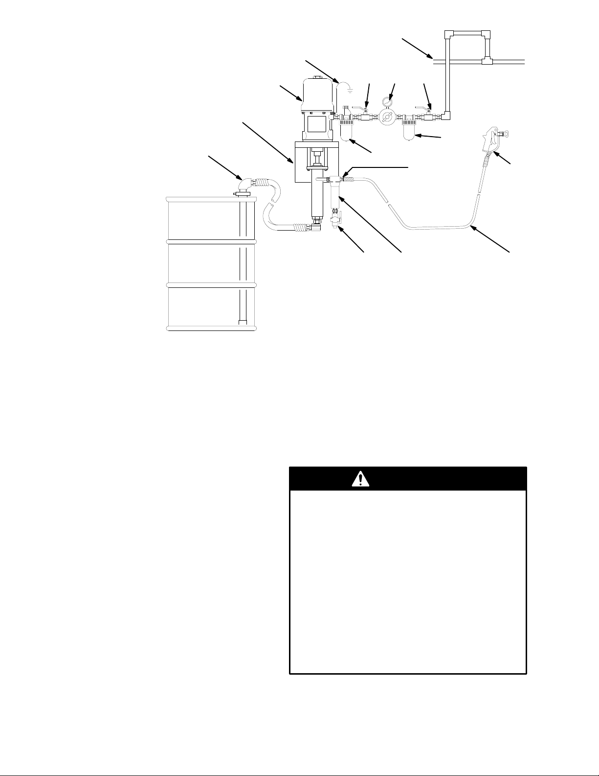
Use the following procedures to install Model 221-123
Heated
System, or to convert an
existing Model 222-268
to a heated system. The V iscon Heater is available in
three
voltages
(see page 18). Specify which voltage you
desire.
To
install the pump, first follow steps 1-3 under
Installing
Pump Model 222-268
on page 7.
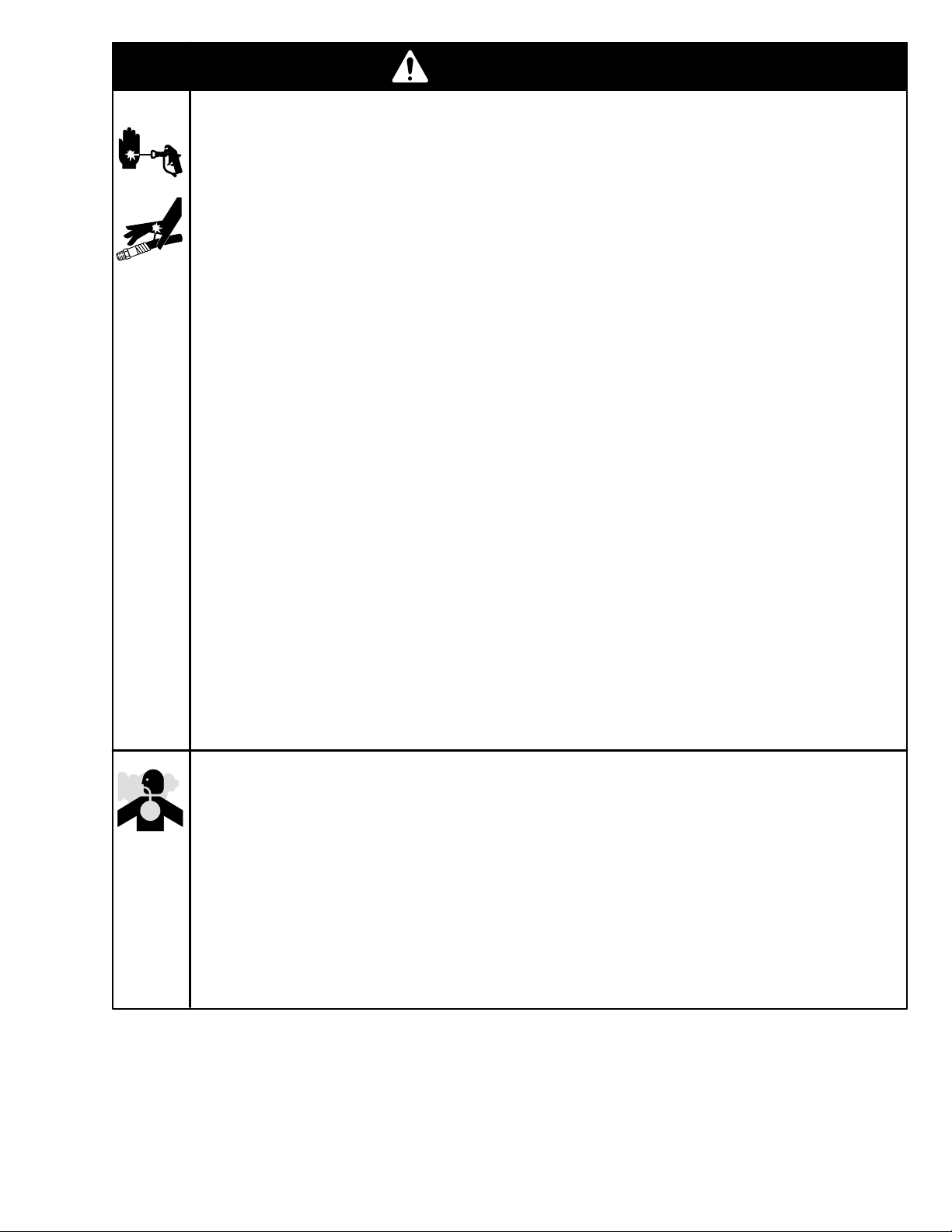
Heat
causes fluid to expand. If fluid in the heated por
-
tion of your system is trapped with no where to ex-
pand, it can cause a system rupture. A system rup-
ture can result in serious bodily injury and property
damage.
Be sure your system has an adequate
way
to
handle heat expansion.
Use flexible hoses between the heater and gun
or, install a properly sized accumulator down-
stream
from the heater
or, install a pressure relief valve, pre–set to re-
lieve pressure when it exceeds the system’ s
maximum
working pressure
and,
never install any shutof
f device between the
heater
and gun. If you are using a fluid
regulator
before
the gun, never use
it as a shutof
f device.
WARNING
The Viscon Heater must be installed by a qualified
electrician in compliance with all state and local
codes and regulations, to reduce the risk of electric
shock
or other serious bodily injury during installation
or
operation.
The power supply must match the heater ’s require-
ments (see Accessories on page 18). Refer to the
Viscon
Heater
Manual, 307-805, for further informa
-
tion.
WARNING
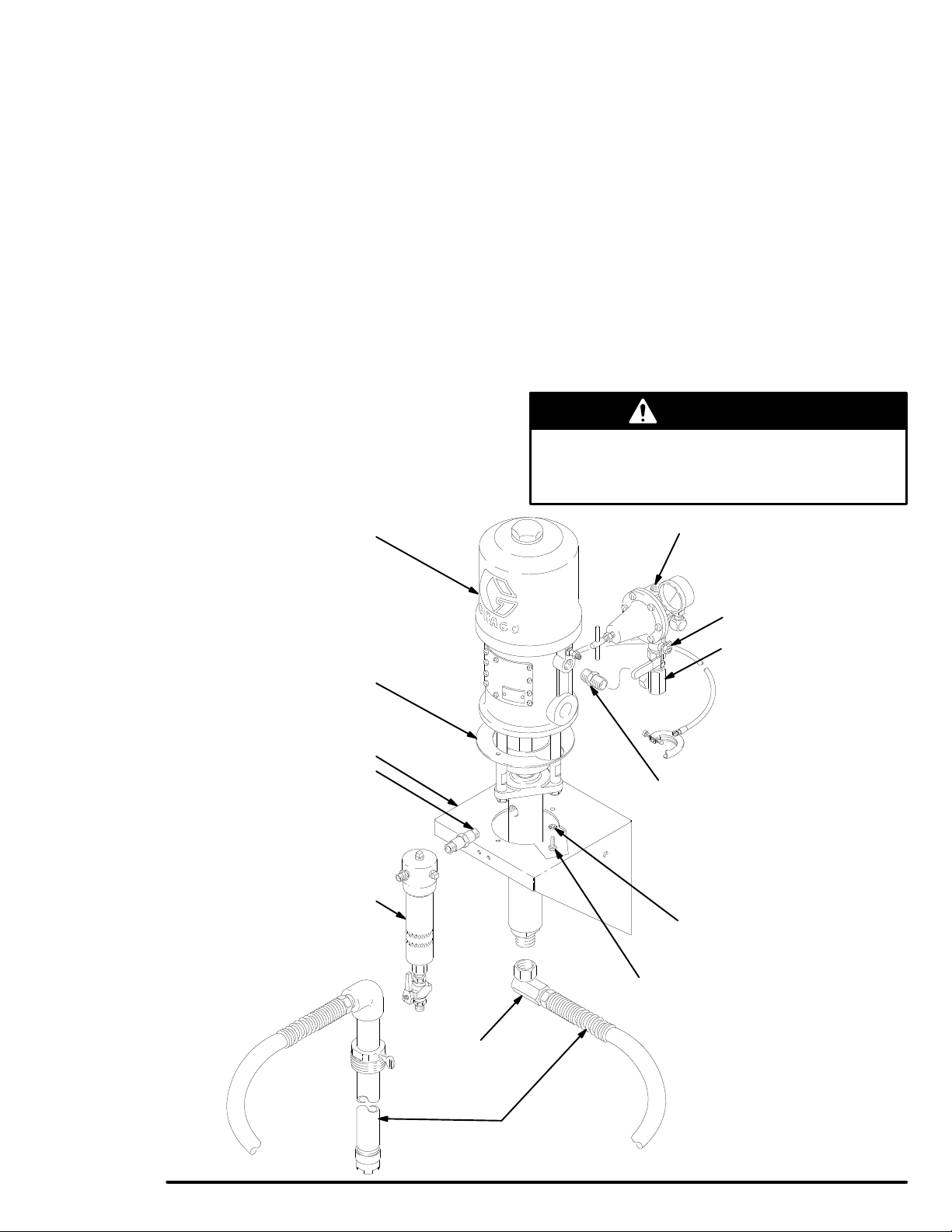
Installing Heater Mounting Kit 222-269
Before
installing the
heater, heater mounting kit and
circulating
kit, follow the
Pressure Relief Procedure
on
page 5. Disconnect all hoses from the pump.
WARNING
NOTE: Reference
numbers
marked with an asterisk (for
example,
22*) are included in kit 222-269.
Apply
pipe
sealant (3*) to all male threads except
at
swiveling connections.
1. Be sure the wall is strong enough to support the
weight
of the heater
, hoses, fluid, and stress
caused
during operation. Locate the heater wall bracket
(22*) holes 9.25” (235 mm) to the left of the pump
bracket holes, and at the same height. Use the
heater wall bracket as a template to mark the wall.
See
Mounting Dimensions
on page 19.
2. Attach
the heater wall bracket to the heater mounting
posts with the M8 x 1.25 screws and lockwashers
supplied
with the heater (39).
3. Use M8 or 5/16” bolts of the appropriate length and
lockwashers (not supplied) to fasten the heater
bracket
to the wall.
4. If you are converting an existing pump, remove
the
fluid filter (8) and
long 3/8 npt nipple (9) from the
pump fluid outlet. Discard the long nipple (9). See
Fig.
2.
5. Install the 3/8 npt nipple (28*) in the heater outlet.
Screw the fluid filter (8) inlet onto this nipple. Un-
screw the 1/4 npt nipple (1 1) from the filter outlet.
Screw
the elbow (40*)
into the filter outlet, and screw
the
nipple (1
1) into the elbow
. See Fig. 3.
6.
Screw the elbow (23*) into the heater
’
s inlet.
Attach
the heater hose (24*) to the elbow . Attach the rigid
end of the union (25*) to the other end of the hose
(24*).
See Fig. 3.
7. Screw the elbow (27*) into the pump outlet. Screw
the
check valve (26*) into the elbow
. Be sure the ar
-
row
on the check valve points down. T
o complete the
heater connection to the pump, screw the swivel end
of
the union (25*) onto the check valve (26*).