ALGAE-X STS 6000-4GPM Installation guide

STS 6000-4GPM
Automated Fuel Filtration System
Installation, Operating and Maintenance Manual
Optimal Fuel Quality Provides Peak Engine Performance
Improves Engine Reliability
Removes Water & Sludge
Prevents Tank Sediments
Optimizes Fuel Quality
Stabilizes Fuel

STS 6000-4GPM ALGAE-X2007-Rev. B
2
INSTALLATION, OPERATING AND MAINTENANCE MANUAL
CONTENT
OVERVIEW –BASIC SYSTEM COMPONENTS ...................................................................... 5
GENERAL SPECIFICATIONS................................................................................................... 6
SYSTEM COMPONENTS......................................................................................................... 6
PRIMARY INSPECTION ........................................................................................................... 7
INSTALLATION......................................................................................................................... 8
Mounting................................................................................................................................ 8
Electrical ................................................................................................................................ 8
Plumbing................................................................................................................................ 8
Typical plumbing / Above ground tank installation (schematically) ........................................ 9
IMPORTANT INSTALLATION PRECAUTIONS........................................................................ 9
PRIMING THE SYSTEM ......................................................................................................... 10
INITIAL START-UP / COMMISSIONING CHECKLIST............................................................ 11
Flow switch setting / adjustment (“No Flow Alarm”) ............................................................. 11
Initial test procedure............................................................................................................. 11
OPERATION ........................................................................................................................... 12
Emergency Stop .................................................................................................................. 12
Pump Operation................................................................................................................... 12
Programming the Timer ....................................................................................................... 12
Fuel Line Leak ..................................................................................................................... 13
Stabilizing and Optimizing Fuel Quality................................................................................ 13
MAINTENANCE ...................................................................................................................... 14
Preventative Maintenance.................................................................................................... 14
Servicing primary filter / strainer........................................................................................... 15
Servicing secondary filter..................................................................................................... 15
TROUBLESHOOTING............................................................................................................. 16
AUTOMATED FUEL FILTRATION SYSTEMS WARRANTY................................................... 18
TECHNICAL ASSISTANCE AND ORDERING........................................................................ 19
Replacement filter elements................................................................................................. 19
STS 6000 SYSTEM IDENTIFICATION.................................................................................... 20
APPENDIX A - ABBREVIATIONS USED IN THIS MANUAL................................................... 21
APPENDIX B –DRAWINGS ................................................................................................... 21

STS 6000-4GPM ALGAE-X2007-Rev. B
3
Automated Fuel Filtration System
STS 6000-4GPM
Three stage water removal and particulate filtration
down to 3 micron
Patented Fuel Conditioner reverses fuel deterioration
& polymerization to submicron levels
Algae-X “Smart Filtration Controller” –UL508A listed
Fully automated programmable control
Automatic shut-down for high vacuum, filter
pressure, leak and flow interruption detection
Integrated industrial display and control panel
Easy installation independent of genset
(“kidney loop”)
Stand alone, safe, reliable, turn key Solution
Ensures Safe & Reliable Emergency
Generator Operation.
The STS-6000 removes water, sludge and prevents
tank sediments in stored fuel.
Fuel is inherently unstable. It naturally forms sediments, solids and tank sludge. Clogged filters, smoke and
damage to injection systems are often symptoms of less than optimal fuel quality causing engines to be unreliable,
smoke, lose power and ultimately fail. Water naturally accumulates in storage tanks due to condensation or leaks in
fills and vents. Water and temperature changes create an environment for microbial growth and natural oxidation,
accelerating formation of sludge, acids and tank corrosion.
Series
STS 6000
Flow rates
4GPM
Tank Size
200 - 5,000 gal
Port Size
3/4” NPT
Power
110V / 60Hz
230V / 50Hz
Weight
~200 lbs
Dim. (HxWxD)
36” x 36” x 12”
LG-X Model
1500
Strainer /
Primary Filter
80 Mesh (178 micron)
10 or 15 micron
Second. Filter
(Water Block)
3 or 10 micron
* Not for use with fluids that have a flash point below 100F
(e.g. Gasoline, Alcohol, …)
The STS 6000 Fuel Filtration Systems are self contained, stand-alone and fully automated. They recondition and
stabilize fuel, eliminate & prevent microbial contamination and remove water, sludge and contaminants from tanks;
preserving the integrity of stored fuel, providing reliable power whenever it is needed.
Implementing STS Fuel Maintenance Systems assures Optimal Fuel Quality & Reliable Engine Performance at
all times. It prevents costly downtime, periodic tank cleaning, replacing out of spec fuel and injection system repairs.

STS 6000-4GPM ALGAE-X2007-Rev. B
4
Customer quotes:
“I had no idea how much sludge accumulated in
my tank, putting my emergency power at risk.”
“We had to learn the hard way that a clogged
filter will shut down the genset –Algae-X
provided us with the perfect “Fuel Solution” so
this will never happen again.”
The principal components are a continuous duty
motor with coupled gear pump, strainer/primary
filter with vacuum sensor & gauge, Algae-X Fuel
Conditioner, and a secondary filter with pressure
gauge & sensor. The system is automatically
operated by the programmable, UL 508A listed
Algae-X Smart Filtration Controller. All
components and control devices are contained
within a fully enclosed, lockable, weatherproof
NEMA 3R cabinet.
The strainer/primary filter protects the pump and
removes water and particulate. The secondary filter
is a quick change spin-on filter designed to remove
emulsified water and contaminants down to 3
Micron.
For safe operation the STS 6000 is equipped with a
drip tray monitored by a leak detector. Additional
safety elements include automatic system shut-
down and indicators when filter elements require
service, high pump vacuum exists or a flow
interruption is detected.
STS 6000 Accessories: AFC-705 Fuel Catalyst,
Wide range of filter elements, Rotor Sight Glass,
Foot Valve, Separ Primary Filter, Two tank control,
Digital flow meter
Fuel Maintenance is an important part of
periodic generator maintenance programs –
just like changing the oil and ensuring the
batteries are charged.
Do you have a “Fuel Maintenance
Program” in place?
Can you afford a clogged filter shutting
down your generator?
When did you last test your fuel or check
the tank for water & sediments?
Call us to engineer & design your “Fuel
Maintenance System”
Typical installation of the STS
Automatic Filtration System

STS 6000-4GPM ALGAE-X2007-Rev. B
5
OVERVIEW –BASIC SYSTEM COMPONENTS
1) Fuel Inlet (From Tank)
11) Motor
2) Inlet Ball Valve
12) ALGAE-X®Magnetic Fuel Conditioner
3) Primary Filter / Strainer
13) Secondary Filter
4) Vacuum Gauge
14) Pressure Switch
5) Drain Valve
15) Pressure Gauge
6) Man. Air Vent / Bleed Screw (located back)
16) Outlet Ball Valve
7) Vacuum Switch
17) Fuel Outlet (To Tank)
8) ALGAE-X®Smart Filtration Controller
18) Mechanical Flow Meter with Flow Switch
9) Pressure Relief Valve
19) Leak Detector (Float Switch) in Spill Tray
10) Gear Pump

STS 6000-4GPM ALGAE-X2007-Rev. B
6
GENERAL SPECIFICATIONS
STS 6000-4GPM
Flow Rate ............................................................ 4 gpm / 240 gph
1,920 Gallons per 8 hour shift
5,760 Gallons per 24 hours
Outline Dimensions (Enclosure) ......................... 36” x 36” x 12” (H x W x D)
System Weight .................................................... approx. 200 lbs
Operating Temperature ...................................... 32 - 104° F; 0 - 40° C
Electrical ............................................................. 115 V / 60 Hz / single phase (standard)
............................................................................. 230 V / 50 Hz also available
Pump .................................................................. Gear Pump
Suction capability (primed) .................................. 15 ft vertical or 100 ft. horizontal lift (lines >3/4”, primed)
Motor ................................................................... 1/2 hp single phase, continuous duty, thermally protected
Timer ................................................................... Programmable Digital Timer
Inlet ..................................................................... 3/4” NPT male port
Outlet .................................................................. 3/4”NPT male port
Max. Fluid Viscosity............................................. 29 cSt
Note: The STS 6000 is designed to meet environmental standards for safe operation.
(NOT for use with fluids that have a flash point below 100F (38C), e.g.: gasoline, alcohol, …)
SYSTEM COMPONENTS
Control and Safety Devices
Algae-X “Smart Filtration Controller” in electrical sub enclosure –UL 508A listed Industrial Control Panel
Programmable Digital Timer –Memory backup to retain program memory during power outages
Pump control switch (Auto-Off-Manual), weatherproof, key operated
Alarm Reset - weatherproof push button
Power available indicator
Pump running indicator
External remote shut-down feature
Inlet and outlet shut off ball valves
Emergency stop button
Pressure relieve valve
Leak sensor and alarm indicator (system shutdown)
Primary filter / strainer high vacuum alarm indicator and system shutdown (vacuum sensor)
Secondary filter high pressure alarm indicator and system shutdown (pressure sensor)
Flow meter with “no flow” alarm indicator and system shutdown (flow switch)
Pump motor starter with single-pole circuit breaker and contactor
Pump / Motor:
Positive displacement gear pump
Relief valve
Motor –UL listed
TEFC (Totally enclosed fan cooled)
Thermal overload protection

STS 6000-4GPM ALGAE-X2007-Rev. B
7
Primary Filter / Fuel Strainer
Fuel filter / strainer with clear bowl
Drain valve on the bottom
Vacuum gauge (stainless steel, liquid filled)
80 Mesh (178 Micron) cleanable stainless steel cartridge standard - other filter elements available
Fuel Conditioner
Inline Fuel Conditioner breaks down naturally forming sediments and solids found in diesel fuel to
submicron levels
Secondary Filter
3 Micron water blocking spin on filter (other filter elements available)
Pressure gauge (stainless steel, liquid filled)
Weatherproof NEMA 3R single door wall-mounted enclosure with lockable handles / latches
14-gauge steel construction with continuously welded seams
Concealed hinges
Finished in gray polyester powder coat inside and out over phosphatized surfaces
Spill tray with leak detection
Louvered side panels
Brackets for wall mounting
Literature pocket
Stainless steel plumbing
PRIMARY INSPECTION
Upon arrival, the STS 6000-4GPM Automated Fuel Filtration System and accessories must be visually inspected
before installation. Improper handling during shipping may cause physical or electrical problems. Immediately
report or note any damages (also concealed ones) to the shipper.
Checklist:
If the packing crate shows signs of damage inspect the STS-6000 cabinet for damage. Check the entire
outside of the cabinet for damage that could indicate internal mechanical or electrical problems.
Check locking handles, door and hinge operation.
Check pump/motor hardware and all plumbing connections for tightness.
Check all electrical terminals and connections for tightness.

STS 6000-4GPM ALGAE-X2007-Rev. B
8
INSTALLATION
! IMPORTANT ! It is recommended that only qualified, experienced personnel, familiar with this
type of equipment, who have read and understood all the instructions in this manual should
install, operate and maintain the system.
MOUNTING
The STS-6000 is a totally enclosed system and should be permanently wall mounted on a hard, level surface.
Use provided mounting feet for proper fastening. This weatherproof unit is designed for well-ventilated indoor
or outdoor use within specified temperature range and should be located as close to the tank as possible.
Please allow about 1 ft of space between the side louvers of the enclosure and nearby objects. This space is
necessary to ensure sufficient ventilation of cooling air for the system and motor.
ELECTRICAL
! WARNING ! To avoid the risk of electric shock make sure that the power supply to the system is
disconnected and ensure that the system is at zero volts, before working on any of the system‟s
electrical parts.
Make sure that the systems power requirements and rated voltage / frequency match your electrical system (See
wiring diagram). The STS 6000 may only be connected to properly grounded power sources for operator safety.
Connect all components to the ground studs provided as shown on the electrical drawings.
! WARNING ! The whole system (Enclosure, doors, plumbing, motor, electric sub panel) must be
properly grounded for operator safety.
Depending on length of run, use #12 AWG or larger copper wiring and connect system to a separate UL listed
20A breaker (not included) appropriate for branch circuit protection.
Note: Wiring and electrical installation must be in accordance with all applicable Federal, State and
Local rules, laws, standards and regulations.
Remote Pump Shut-Down Feature:
If required, connect the “external pump shut down input terminal”(Terminal 15 on Terminal Block “TB2” –see
wiring diagram) for customers use per specification on electric diagram to disable pump (e.g.: remote shut down,
external emergency stop button). Please note that the contact needs to be supplied with +24V DC from the power
supply of the STS 6000 Algae-X Smart Filtration Controller.
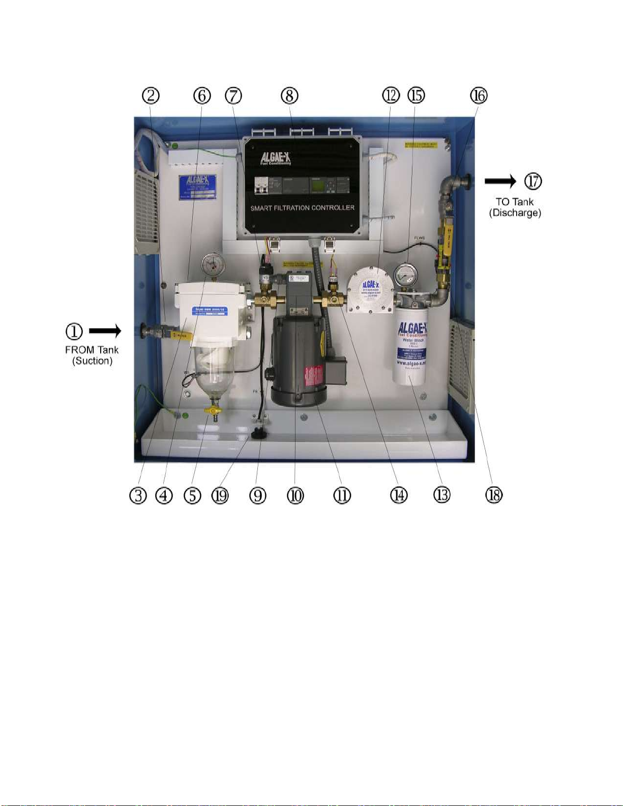
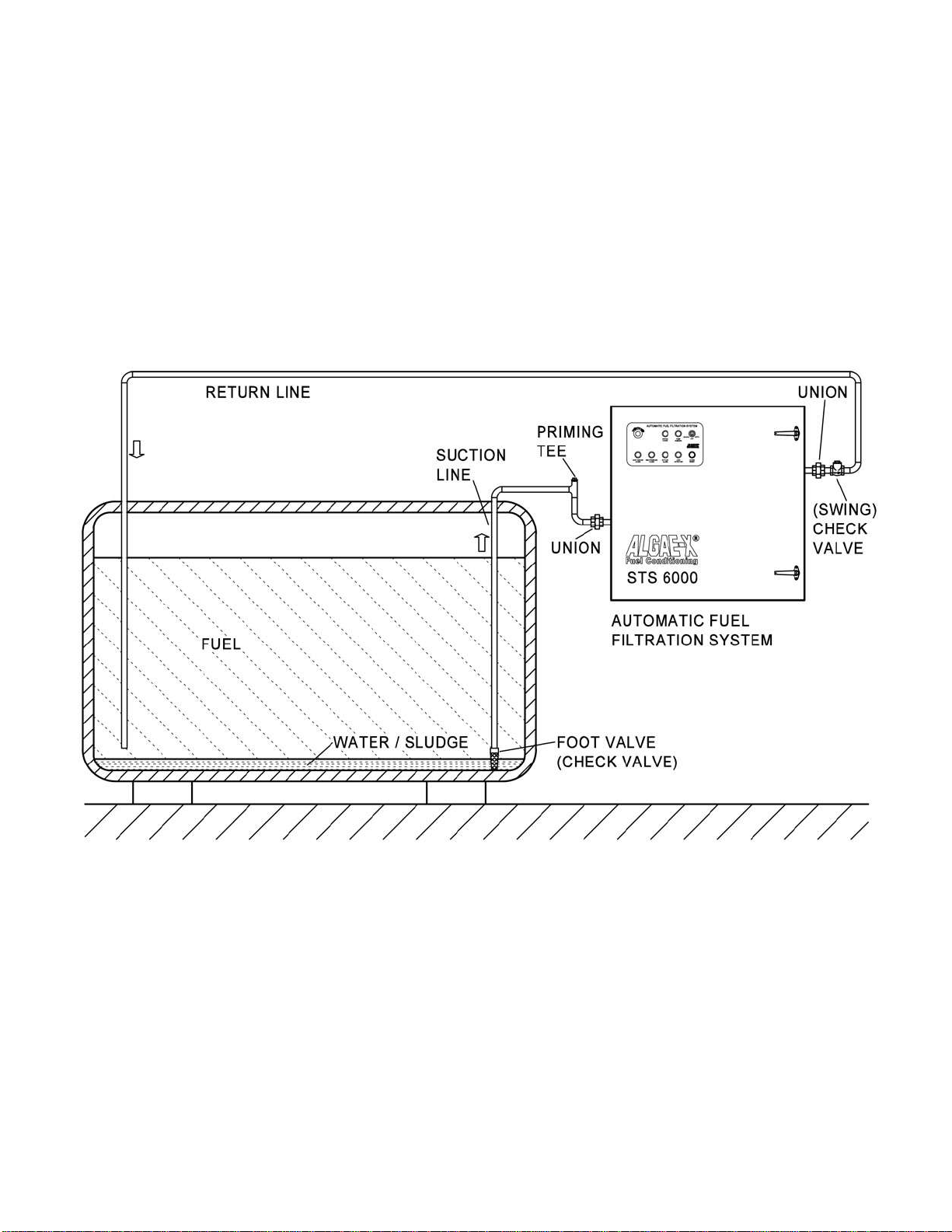
PLUMBING
Use proper quality approved fuel line materials with at least 3/4” inner diameter on the suction side from
the tank and at least 1/2” inner diameter on the return / discharge side back to the tank.
The pick-up tube/line(s) should originate from the lowest point of the tank (to remove all water), should be
connected directly to the system’s “PUMP INLET –SUPPLY FROM TANK” port located on the left hand side of
the enclosure and kept as short as possible. It is recommended to install an oversized, low restriction foot
valve to keep the system primed, especially if the “PUMP INLET –SUPPLY FROM TANK” port of the system is
located above the lowest possible fuel level in the tank. A priming tee should be installed on the highest point
of the suction line to be able to easily prime the lines and system.
The return line(s) should be plumbed to the “PUMP OUTLET –RETURN TO TANK” port (on the right side of the
system) and enter the tank as far as possible from the pick up tube close to the tank bottom. A (swing) check
valve may be required on the return line(s) on some installations to prevent back flow pressure.
`
`
`

STS 6000-4GPM ALGAE-X2007-Rev. B
9
Multiple suction and/or return lines may be connected to a manifold outside the STS-6000 (see options list).
Anti-Siphon or other external plumbing devices may be required –please check local regulations / code.
The system capabilities are 15 ft suction (vertical) or 100 ft horizontal lift, when connected to piping of 3/4” ID or
more with no additional flow restrictions such as valves, 90-degree connectors or other plumbing accessories. For
continuous optimal performance, make sure suction and discharge lines are free and that nothing is blocking the
flow of fuel and that the suction line always stays primed.
Note: Plumbing and Installation must be in accordance with all applicable Federal, State and Local
rules, laws, standards and regulations.
TYPICAL PLUMBING / ABOVE GROUND TANK INSTALLATION (SCHEMATICALLY)
IMPORTANT INSTALLATION PRECAUTIONS
The suction line of the system should be independent and separate from the suction line of the engine. If
that is not possible, appropriate valves must be installed to completely separate the STS-6000 from the engine
fuel system to prevent any possible interference with safe engine operation.
It is highly recommended to plumb the discharge line independent and separate of the engine’s fuel return line
back to the tank. If the return line from the engine and the discharge of the STS 6000 have to be combined in any
way, adequate valves should be installed to prevent any possible interference with safe engine operation.
Note: If any of the STS 6000 system‟s fuel lines are used in combination with the engine‟s fuel system,
the STS 6000 should be disabled during engine operation (use the provided “remote pump shut
down” feature as shown in the electrical drawing and described above).

STS 6000-4GPM ALGAE-X2007-Rev. B
10
PRIMING THE SYSTEM
The pump supplied with the STS 6000 is NOT automatically self-priming and must not be run dry.
! WARNING ! If the pump is allowed to run without fuel, pump damage will occur.
The pump head of the STS 6000 unit is shipped from the factory filled with Diesel #2 to facilitate initial lubrication.
This will not eliminate the necessity to prime the complete system. The STS 6000 is primed by using the
externally installed priming tee (not provided) on the suction side of the system. Also the strainer / primary filter as
well as the suction line has to be completely filled with fuel prior to the initial system start-up.
Priming procedure:
1. Ensure the pump is filled with #2 Diesel fuel.
2. Ensure that the inlet ball valve is in the open and the outlet ball valve is in the closed position.
3. Slightly open the manual air vent valve (bleed screw) located inside the STS 6000 (position #6 –page 5).
4. Open the externally installed priming tee (located at the highest point of the suction plumbing), fill the line
with fuel until fuel escapes from bleed screw (manual air vent), close the manual air vent, continue filling until
all air is bled from the plumbing lines and system, close the priming tee. (for tanks situated on a lower level
than the STS 6000, it is recommended that a foot valve is installed at the fuel tank to hold the fuel column).
5. Make sure to completely fill suction line to its highest point with fuel (no trapped air), in particular when the
suction line exits the tank top and the STS 6000 is located below that level.
6. Open the outlet ball valve and ensure the inlet ball valve is also in open position.
7. Switch on the pump and observe fuel flow.
The system is equipped with a vacuum gauge on the input side of the pump. The gauge should read 0 to 9" HG
vacuum maximum under normal conditions. Vacuum gauge readings reaching 10" HG vacuum indicate excessive
debris in the primary filter/ strainer (or a flow restriction or too high suction height and therefore pressure drop in
the suction line) and will result in pump shutdown and activate the alarm “HIGH VACUUM ALARM”.
Note: 10" HG vacuum = clogged primary filter / strainer or suction line flow restriction / excessive lift.
The system’s pressure gauge on the secondary filter should show 25 PSI maximum pressure under normal
conditions (.433 PSI = 1' vertical head pressure). Pressure gauge readings in excess of 25 PSI pressure indicate
excessive filter, or fuel line restrictions and/or friction.
System pressure over 25 PSI indicates a high-pressure failure (“HIGH PRESSURE ALARM” indicator) and will
automatically shut down the pump.
The pressure relief valve has a 35-40 PSI set point. System pressure in excess of 35-40 PSI will cause the
pressure relief valve to open and vent fuel back to the fuel transfer pump inlet side.
`

STS 6000-4GPM ALGAE-X2007-Rev. B
11
INITIAL START-UP / COMMISSIONING CHECKLIST
FLOW SWITCH SETTING / ADJUSTMENT (“NO FLOW ALARM”)
Please make sure system is properly primed and check when pump running for a steady stream of fuel without air
bubbles in the mechanical flow meter (indicator) inside the STS 6000 enclosure. If the “NO FLOW ALARM” alarm
light is blinking (and after 10 seconds illuminate continuously as the pump is turned off) the flow switch located on
the side of the mechanical flow meter needs to be adjusted to the actual flow rate.
This can be easily done by sliding the switch carefully up or down (while pump is running) and lining up the black
flow switch with the red indicator ring inside the sight tube of the flow meter showing the actual flow rate. For
further information please see enclosed instruction sheet.
You can reset the alarm by pushing the “ALARM RESET” button located on the control panel.
INITIAL TEST PROCEDURE
With breakers and power turned on and pump running check all alarms for proper operation:
1) Manually raise float switch located in drip/spill tray. Pump should immediately turn off and “LEAK
DETECTION” should illuminate. Reset alarm by pushing the “RESET ALARM” button on the control
panel.
2) Slowly partially close inlet ball valve. At 10”HG pump should turn off and “HIGH VACUUM ALARM”
should illuminate. Open inlet ball valve again. Reset alarm by pushing the “RESET ALARM” button.
3) Slowly partially close outlet ball valve. At 25 PSI pump should turn off (after a delay of about 1
second) and “HIGH PRESSURE ALARM” should illuminate. Open outlet ball valve again Reset alarm
by pushing the “RESET ALARM” button.
4) Slide the flow switch located on the side of the mechanical flow meter slightly upwards away from the
flow indicator inside the sight tube (mark original position before doing so). The “NO FLOW ALARM”
indicator should start blinking for 10 seconds and then illuminate constantly as the pump is turned off.
Slide flow switch back into original position and reset alarm by pushing the “RESET ALARM” button.
Note: If any of the above described alarm test procedures fail or if any alarm trip value deviates
immediately contact Algae-X International.

STS 6000-4GPM ALGAE-X2007-Rev. B
12
OPERATION
! WARNING ! Do not use with gasoline. This System is not meant for use with gasoline nor with
other flammable liquids having a flash point less than 100°F. Use with gasoline or use with any
flammable liquids at a temperature exceeding their flash point, presents an immediate explosion
and fire hazard.
! WARNING ! Never use the STS 6000 at a temperature exceeding the flash point of its contents.
EMERGENCY STOP
Note: In case of an emergency the pump can be turned off and disabled by depressing the red
“EMERGENCY STOP” button on the control panel.
To release the “EMERGENCY STOP” button located on the control panel turn the red knob in the direction
indicated by the arrows on the mushroom button and push the “ALARM RESET” button to acknowledge.
PUMP OPERATION
Apply control power to unit. Place breakers in the Algae-X Smart Filtration Controller in the “ON” position.
Automatic:
Place the key switch in the “AUTO” position. When the timer contacts close, the pump will start and run until the
timer setting has expired.
Manual (Override):
Place the key switch in the “RUN” position. The pump motor will run until the switch is returned to the “OFF” or
“AUTO” mode positions or till an alarm or overload has been tripped.
PROGRAMMING THE TIMER
The programmable timer is part of the Micro PLC settings of the Algae-X Smart Filtration Controller located inside
the STS 6000 system.
Note: The PLC uses military time –all times programmed must be in that format.
1. Please make sure the Emergency Stop button is not engaged, the key switch set to “OFF” and push the
“ALARM RESET” button on the control panel.
2. When power is first applied to the system the display of the PLC will show (blinking) date and time.
3. We will now set current date and time (must be in military format):
4. Hit the “ESC” button
5. Select „Stop‟and press “OK”
6. Select „Yes‟(use down arrow key) and press “OK”
7. Select „Setup‟(use down arrow key)and press “OK”
8. Select „Clock‟and press “OK”
9. Select „Set Clock‟and press “OK”
10.Using the arrow keys set current day of the week, time and date as indicated in the display and press “OK”
( or to change value, or to change between week day, time and date).
11.When finished entering press “OK” to confirm
12.Press “ESC”
13.Select „Start‟and press “OK” –correct time and date should be displayed
`
`

STS 6000-4GPM ALGAE-X2007-Rev. B
13
14.We are now ready to program the timer (military time format must be used):
15.Hit the “ESC” button
16.Select „Set Param‟(use down arrow key) and press “OK”
17.Push down arrow key till „Timer 1‟ is displayed
18.Press “OK”
19.Use left and right arrow keys to select the day/days of the week the system should automatically turn
on and the up or down arrow key to activate the selected day.
20.Use arrow keys in same manner to program the „On‟ time –when the system will switch on (on the selected
day/days)
21.Use arrow keys in same manner to program the „Off‟ time –when the system will switch off (on the selected
day/days)
22.Press “OK” to confirm entry when finished
23.If required you can set up to 3 Timers by using the up and down arrow key
24.Press “ESC” twice to return back to the time and date display
Please call Algae-X International with any questions.
FUEL LINE LEAK
If fuel is detected in the spill / drip tray, the float switch will activate the fuel leak alarm illuminating the “LEAK
DETECTION” indicator. The pump motor will shut off and remain locked out of operation until the leak has been
corrected and the “ALARM RESET” button has been pushed.
Before removing the spilled fuel from the basin, turn the key switch to the “OFF” position.
Always make sure to find the cause of the leakage and correct it. After removing the spilled fuel, allowing the leak
switch to return to its normal position, the key switch can be returned to the “AUTO” or “RUN” mode.
Note: Disposal of fuel and associated waste should be done in accordance with Federal, State and Local
regulations.
STABILIZING AND OPTIMIZING FUEL QUALITY
We recommend treating the fuel with the ALGAE-X® Fuel Catalyst (AFC-705). This will enhance and accelerate
the tank cleaning process by breaking down and dissolving existing tank sludge. AFC-705 will decontaminate
compartments of the tank that are out of reach of the suction line. Depending on the condition of the fuel and the
amount of sludge build-up, it is recommended to initially use a double dose of one to twenty-five hundred (1:2500)
instead of one to five thousand (1:5000) This has proven to be essential in accelerating the tank cleaning process.
AFC-705 contains detergent, surfactant, dispersant, corrosion inhibitor, lubricity enhancer and combustion
catalyst. It does not contain biocides. AFC-705 should always be used periodically in particular to stabilize fuel
that is stored for longer periods of time.
Note: In cases of severe tank contaminant build-up (sludge) and high water level in bottom, it is
recommended to clean the tank (vacuum bottom) and polish the fuel before initial use of an STS
system.

STS 6000-4GPM ALGAE-X2007-Rev. B
14
MAINTENANCE
! IMPORTANT ! It is recommended that only qualified, experienced personnel, familiar with this
equipment, who have read and understood all the instructions in this manual should install,
operate and maintain the system.
! IMPORTANT ! Always disconnect the system from the electric power supply before working or
servicing it. Do not proceed with any maintenance unless the pressure or vacuum has been
released, the system has been allowed to reach ambient temperature and all fluids have been
drained.
PREVENTATIVE MAINTENANCE
The STS-6000 Automated Fuel Filtration System should be visually inspected and tested a minimum of every
six months according to the procedure below during light duty cycles. Monthly inspections are recommended
for systems that are being used in excess of an average of 8 hours day and five days a week.
Prior to performing the maintenance procedure ensure that:
1) The electrical sub-panel mounted main disconnect switch is operating properly,
2) the user supplied remote circuit breaker is in the “Off” position, and
3) that all sources of power are isolated from the unit.
4) Proceed only after this has been verified and properly tagged.
Drain visible water and sediment from primary filter / strainer (see Servicing Primary Filter / Strainer below).
Check enclosure and all parts for corrosion and rust.
Check locking latches, door and hinge operation.
Check cabinet mounting hardware. Tighten as necessary.
Check pump/motor hardware for tightness. Pump/motor hardware will loosen after normal operation due to
vibration. This hardware is lock nutted, check all bolts for secure nuts.
Check all electrical terminals and connections for tightness.
All motors are permanently lubricated and do not require any lubrication.
All pumps are self-lubricating and do not require any maintenance.
Check all plumbing joints for leaks. Tighten fittings and joints as necessary. Remove accumulated fuel in drip
tray as necessary.
Inspect all filters, strainers and separators. See section below on filter inspection and service.
With breakers and power turned on again and pump running check all alarms for proper operation:
1) Manually raise float switch located in drip/spill tray. Pump should immediately turn off and “LEAK
DETECTION” should illuminate. Reset alarm by pushing the “RESET ALARM” button on the control
panel.
2) Slowly partially close inlet ball valve. At 10”HG pump should turn off and “HIGH VACUUM ALARM”
should illuminate. Open inlet ball valve again. Reset alarm by pushing the “RESET ALARM” button.
3) Slowly partially close outlet ball valve. At 25 PSI pump should turn off (after a delay of about 1
second) and “HIGH PRESSURE ALARM” should illuminate. Open outlet ball valve again Reset alarm
by pushing the “RESET ALARM” button.
4) Slide the flow switch located on the side of the mechanical flow meter slightly upwards away from the
flow indicator inside the sight tube (mark original position before doing so). The “NO FLOW ALARM”
indicator should start blinking for 10 seconds and then illuminate constantly as the pump is turned off.
Slide flow switch back into original position and reset alarm by pushing the “RESET ALARM” button.
Note: If any of the above described alarm test procedures fail or if any alarm trip value deviates
immediately contact Algae-X International.
`
`

STS 6000-4GPM ALGAE-X2007-Rev. B
15
SERVICING PRIMARY FILTER / STRAINER
Clogging filter elements restrict the flow of fuel and the system’s vacuum gauge will indicate a pressure drop. The
gauge is mounted on the inlet side of the pump. At a pressure drop of 10” HG, the pump will automatically shut off
and activate the “HIGH VACUUM ALARM” indicator light. The signal indicates that it is time to clean or change
the filter element.
Servicing and cleaning primary filter / strainer:
1. Turn key switch to the “OFF” position –make sure pump will not turn on
2. Close the inlet and outlet ball valves
3. Open the brass colored bleed screw (manual air vent)
4. Place a fuel waste container below the drain valve on the bottom of the clear filter bowl
5. Open the drain valve (turn counter clockwise)
6. Close after visible sediment, particles and water have been drained from the bowl
7. Remove filter bowl with provided filter wrench and unscrew filter element
8. Either replace filter element or clean stainless steel wire mesh strainer –make sure gasket is in place on top
of filter element / strainer
9. Prime the filter bowl up to the top by pouring clean diesel fuel into the clear filter bowl
10. Make sure gasket on top of bowl is aligned, has oil film applied and reattach filter bowl
11. Close bleed screw (manual air vent)
12. Open the inlet and outlet ball valve
13. Push the “ALARM RESET” button on the control panel to acknowledge the alarm and reset it
14. Return the pump selector key switch to “AUTO” or “RUN”
15. Should air be trapped in the filter bowl / lines please re-prime according to Priming Procedure.
Your system is now ready to resume normal operation
SERVICING SECONDARY FILTER
Clogging filter elements and saturation of the water block filter restrict the flow of fuel and the system’s pressure
gauge will indicate a pressure drop. The gauge is mounted on top of the secondary filter. At a pressure drop of 25
PSI (red dial area of the gauge) the pump will automatically shut off and activate the “HIGH PRESSURE ALARM”
indicator light. The signal indicates that it is time to change the filter element.
There are several types of Algae-X spin on fine filters available; we recommend using the WBS-3 (3 micron water
block fine filter). The Algae-X Water Block incorporates polymer technology to remove emulsified water from fuel.
Changing the secondary filter:
1. Turn key switch to the “OFF” position – make sure pump will not turn on
2. Close the inlet and outlet ball valve
3. Place an appropriate container underneath the filter
4. Remove old spin on filter by turning the cartridge counter clock wise seen from the bottom of the cartridge
5. Apply a film of lubricating oil to the gasket of the new filter. Screw the new filter canister to the filter head
until the gasket is tight and secure (an additional ½ to one turn after the filter makes contact with the gasket)
6. Open the inlet and outlet ball valve
7. Push the “ALARM RESET” button on the control panel to acknowledge the alarm and reset it
8. Return the pump selector key switch to “AUTO” or “RUN”
9. Check for leaks when re-starting and pressurizing the system
Your system is now ready to resume normal operation
Note: Disposal of fuel, associated waste and filters should be done in accordance with Federal, State
and Local regulations.
! WARNING ! Some fuels may have been treated with biocides. Biocides are extremely toxic and
may enter the body through the skin. It is recommended to use adequate protection and proper
precautions if fuel contains biocide type products.
`

STS 6000-4GPM ALGAE-X2007-Rev. B
16
TROUBLESHOOTING
No fuel delivery
1. Pump does not run
2. Pump is not primed
3. Fuel supply line blocked
4. Excessive lift
5. Air leak in fuel supply to pump
6. Pump rotation direction incorrect
7. Intake or outlet valve closed
8. Check valve installed backwards
Insufficient fuel delivered
1. Air leak at inlet
2. Defective pressure relief valve or check valve
3. Excessive lift
4. Pump worn
5. Inoperative foot valve
6. Piping improperly installed or dimensioned
7. Primary filter/strainer plugged
Rapid pump wear
1. Pipe strain on pump causing bind
2. Worn pump/motor coupler
3. Pump has been run dry or with insufficient fuel
4. Plumbing on inlet side not appropriately dimensioned
Alarm “HIGH VACUUM ALARM” comes on with clean or new filter element installed
1. Heavily contaminated fuel / excessive water in tank
2. Restriction in plumbing on inlet side too high
3. Excessive lift
4. Inoperative foot valve
5. Inlet ball valve not fully open
6. Suction line clogged
Alarm “HIGH PRESSURE ALARM” comes on with clean or new filter element installed
1. Heavily contaminated fuel / excessive water in tank
2. Restriction in plumbing on discharge side too high
3. Head (lift) on discharge side too high
4. Check valve stuck or defective
5. Outlet ball valve not fully open
6. Discharge line clogged
Pump requires too much power
1. Air in plumbing lines
2. Liquid too viscous
3. Bent pump shaft, binding rotor
4. Misalignment of pump/motor coupler

STS 6000-4GPM ALGAE-X2007-Rev. B
17
Noisy operation
1. Insufficient fuel supply
2. Air leaks in the inlet pipe
3. Air or gas in fuel on the suction side
4. Pump and motor out of alignment
5. Worn out spider coupling
6. Pump coupler out of balance
Pump requires frequent re-priming
1. Inoperative foot valve
2. Inoperative check valve
3. Inoperative solenoid valve (optional)
4. Pump cavitations
5. Plumbing air leaks
6. Lift too high
7. Leaking pump seal
Motor does not turn or turns intermittently
1. Control power not available
2. Motor thermal overload condition
3. Pump failed and seized
4. Motor failure
5. Emergency Button depressed
Pump leaks fuel
1. Loose pump plumbing fittings
2. Worn pump shaft seal
3. Pump pressure relief valve failure
4. Fuel leak elsewhere and fuel dripping or running towards the pump
5. Excessive head from overhead storage tank
6. Worn pump O-rings or seals

STS 6000-4GPM ALGAE-X2007-Rev. B
18
AUTOMATED FUEL FILTRATION SYSTEMS WARRANTY
LIMITED WARRANTY
ALGAE-X® International makes every effort to assure that its products meet high quality and durability standards
and expressly warrants the products described herein, against defects in material and workmanship for a period
of one (1) year from the date of purchase. This warranty is not intended to supplant normal inspection, care and
service of the products covered by the user, and shall not obligate ALGAE-X® to provide free service during the
warranty period to correct breakage, maladjustment or other difficulties arising out of abuse, misuse, or improper
care and maintenance of such products. Our express warranty is subject to the following terms and conditions:
1. This warranty shall only extend to and is only for the benefit of original purchasers who use the products
covered hereby
2. Any warranty claim received by ALGAE-X®after one (1) year from the date of purchase will not be honored
even if it is claimed that the defect occurred prior to one (1) year from the date of purchase.
3. This warranty shall not apply to products (1) which have been tampered with, altered or repaired by anyone
other than ALGAE-X®without the express prior written consent of ALGAE-X®(2) which have been installed
improperly or subject to misuse, abuse, accident, negligence of others, improper operation or maintenance,
neglect or modification, or (3) which have had the serial number altered, defaced or removed.
4. The liability of ALGAE-X®under this warranty is limited to the repair or replacement of the defective product.
ALGAE-X®assumes NO LIABILITY for labor charges or other costs incurred by any purchaser incidental to
the service, adjustment, repair, return, removal or replacement of products. ALGAE-X®ASSUMES NO
LIABILITY FOR ANY GENERAL, SPECIAL, INCIDENTAL, CONSEQUENTIAL, CONTINGENT OR OTHER
DAMAGES UNDER ANY WARRANTY, EXPRESS OR IMPLIED, AND ALL SUCH LIABILITY IS HEREBY
EXPRESSLY EXCLUDED.
5. ALGAE-X®MAKES NO WARRANTIES, EXPRESS OR IMPLIED, OF MERCHANTABILITY, FITNESS FOR A
PARTICULAR PURPOSE OR OTHERWISE, WITH RESPECT TO THE PRODUCTS COVERED BY THIS
WARRANTY POLICY, EXCEPT AS EXPRESSLY PROVIDED FOR HEREIN. NO EMPLOYEE, AGENT,
REPRESENTATIVE OR DISTRIBUTOR IS AUTHORIZED TO MAKE ANY WARRANTY ON BEHALF OF
ALGAE-X®OTHER THAN THE EXPRESS WARRANTY PROVIDED FOR HEREIN.
6. ALGAE-X®reserves the right at any time to make changes in the design, material, function and specifications
of its products. Any such changes shall not obligate ALGAE-X®to make similar changes in such products that
were previously manufactured.
WARRANTY CLAIM PROCEDURE
To make a claim under this warranty, please call our ALGAE-X® at (239) 690 9589 or (877) 425-4239, and
provide: Name and location where unit was purchased, the date and receipt of purchase, model number, serial
number, and a detailed explanation of the problem you are experiencing. The Customer Service Representative
may, at the discretion of ALGAE-X®, arrange for a Field Engineer to inspect your system. If the inspection
discloses a defect covered by its limited warranty, ALGAE-X® will either repair or replace the defective parts or
products. ALGAE-X® assumes no liability, if upon inspection, ALGAE-X® or its representative determines that
there is no defect or that the damage to the system resulted from causes not within the scope of this limited
warranty. For service and sales, please contact ALGAE-X®:
ALGAE-X®International
5400-1 Division Drive, Fort Myers, FL 33905 ▪ 877-425-4239 ▪ Fax: 239-690-1195
Internet: www.algae-x.net ▪ Email: algae-x@algae-x.net

STS 6000-4GPM ALGAE-X2007-Rev. B
19
TECHNICAL ASSISTANCE AND ORDERING
Please write to, fax, email or call:
ALGAE-X® International
5400-1 Division Drive
Fort Myers, FL 33905
Tel: 239-690-9589
Fax: 239-690-1195
Email: algae-x@algae-x.net
Internet: www.algae-x.net
Please provide the following information:
Serial Number of your STS 6000, the required part numbers and quantity.
The drawings / parts list included in this manual are the most accurate source of part numbers for your STS 6000.
REPLACEMENT FILTER ELEMENTS
Primary Filter:
TK-084 80 Mesh (178 Micron) Stainless Steel re-usable, cleanable filter element - STANDARD
TK-081 10 Micron filter element
TK-082 15 Micron Water Block filter element
TK-088 Filter Wrench
Secondary Filter:
WBS-3 3 Micron Water Block spin on filter cartridge
FFS-10 10 Micron spin on filter cartridge (not water blocking)
Also available:
Larger or smaller capacity, custom designed systems for higher or lower flow rates
Two Tank Control
Digital Flow Meter
Separ Primary Filter (OPTION –S)
Foot Valves
Rotor Sight Glass

STS 6000-4GPM ALGAE-X2007-Rev. B
20
STS 6000 SYSTEM IDENTIFICATION
Serial Number: _____________________________ (e.g. B 070010 –6040)
System Specification:
Voltage:
120 V AC / 60 Hz
230 V AC / 50 Hz
Primary Filter Element:
178 Micron Stainless Steel
10 Micron
15 Micron Water Block
Secondary Filter Element:
3 Micron Water Block
10 Micron Fine Filter
Inspected by: ______________________________ Date: ________________
Table of contents
Popular Laboratory Equipment manuals by other brands

reci
reci W Series instruction manual

Panasonic
Panasonic NU-MX100P operating instructions

Waters
Waters Xevo G2 QTof Operator's, overview and maintenance guide

Prior Scientific
Prior Scientific PureFocus850 installation guide

Agilent Technologies
Agilent Technologies Agilent 33500 Series user guide

Biohit
Biohit eLine 730020 instruction manual