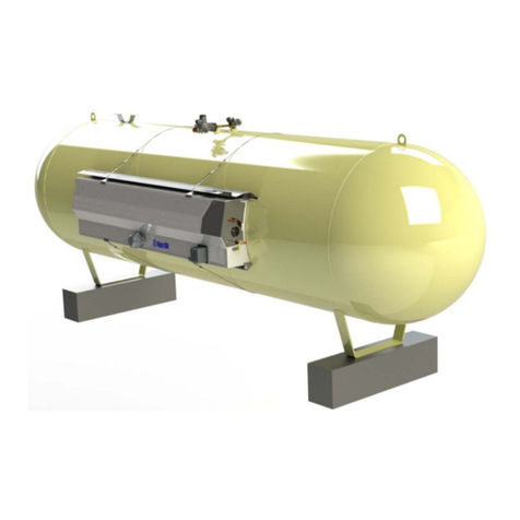
Algas SDI VAPORAIRE Series Manual

Operations & Maintenance
Manual
151 S. Michigan Street, Seattle, Washington, USA 98108
Tel: 206-789-5410 Fax: 206-789-5414 Web: www.algas-sdi.com
MANUAL PN 54264 VAPORAIRE REV 08-26-19
Digitally signed by
Ana Torres
Date: 2019.08.26
15:28:24 -07'00'

WARNING
Read the OPERATION MANUAL before operating this equipment.
DISCLAIMER
Algas-SDI International, LLC (ASDI) shall not be liable for technical
and/or editorial errors or omissions in this manual. ASDI makes no
warranties, express or implied, including the implied warranties of
merchantability and fitness for a particular purpose with respect to
this manual. In no event shall ASDI be liable for any special or
consequential damages including, but not limited to loss of
production time, or loss of profits.
■NOTE: Algas-SDI reserves the right to use alternate manufacturers’
components as vendor delivery applicability dictates. Vendors
have supplied literature contained in the Operation Manual.
Please check to be sure supplied data matches your
configuration. Contact Algas-SDI if any questions exist.
■This equipment uses LPG-a flammable fuel, or NH3-a toxic gas,
(depending on the model), handled under pressure. Inherent hazards
exist, and a thorough understanding of the equipment is required to
allow safe operation and maintenance.
■Allow only a TRAINED and FULLY QUALIFIED PERSON to service this
equipment.
■Any time a component must be replaced, use the same type, model, etc.
DO NOT SUBSTITUTE! The consequences from such actions are
unpredictable and may lead to dire consequences. When components
are replaced with components not approved for use in our FM/CSA
listed equipment, the FM/CSA listing becomes void for that unit.

WARRANTY REGISTRATION
Fill out the Warranty Registration information on the last page of this manual to
register your equipment. Then make a photocopy and mail to the address shown
at the bottom.
WARRANTY, COPYRIGHTS and APPROVALS
WARRANTY
Algas-SDI International, LLC (ASDI) warrants that the equipment is free of
defects in materials and workmanship under normal use and service. ASDI
agrees to repair or replace, at our option, without charge f.o.b. factory, any part
which has proven defective to the satisfaction of Algas-SDI International, LLC
within one (1) year from the date of the original installation or within 18 months
from the date of shipment, whichever is earlier. Equipment, which in the opinion
of ASDI, has been damaged by improper installation or operation, or has been
abused or tampered with in any way, will not be accepted for return under
warranty.
Algas-SDI International, LLC will not accept back charges for work performed by
others upon or in conjunction with ASDI equipment, unless prior authorization is
given by means of an Algas-SDI International, LLC purchase order. Algas-SDI
International, LLC will not be liable by reason of shutdown, non-operation or
increased expense of operation of other equipment, or any other loss or damage
of any nature, whether direct or consequential, arising from any cause
whatsoever.
Algas-SDI International, LLC makes NO other warranty of any kind, whatsoever
expressed or implied; and all warranties of merchantability and fitness for a
particular purpose are hereby disclaimed by Algas-SDI International, LLC and
excluded from these terms of sale. No person has any authority to bind Algas-
SDI International, LLC to any representation or warranty other than this warranty.
COPYRIGHT
© Copyright 1999, 2013, 2019 by Algas-SDI International, LLC, Seattle,
Washington 98108.
All rights reserved. No part of this manual may be reproduced or copied in any
form or by any means, photographic, electronic, or mechanical, without the prior
express written consent from Algas-SDI International, LLC, Seattle, Washington,
USA.
APPROVALS

SYMBOLS and CONVENTIONS
Special symbols are used to denote hazardous or important
information. You should familiarize yourself with their meaning and
take special notice of the indicated information.
Please read the following explanations thoroughly.
GENERAL WARNING OR CAUTION
This symbol indicates hazards or unsafe practices, which can result
in damage to the equipment or cause personal injury. Use care and
follow the instructions given.
FLAMMABLE GAS HAZARD
This Symbol indicates a potential hazard, which can result in severe
personal injury or death. Use extreme care and follow the
instructions given.
ELECTRICAL DISCONNECT REQUIRED
This symbol indicates a potentially dangerous situation, which can
result in severe personal injury or death or damage to equipment.
Use great care and follow the instruction given.
ASDI CONTACT NUMBERS
If you have questions, need help with your equipment, or want
information on other products, contact Algas-SDI at:
Global Support Center: +1-206-762-HELP (4357)
Telephone: 206.789.5410
Facsimile: 206.789.5414
Email: sales@algas-sdi.com
Internet: http://www.algas-sdi.com

Table of Contents
1.Introduction.................................................................................................................................................... 1-1
General ............................................................................................................................................................ 1-1
DESCRIPTION ................................................................................................................................................ 1-1
MIXER OPERATION - LPG-VAPOR/AIR MIXING PROCESS .......................................................................... 1-2
LPG-Vapor/Air Mixing Process ........................................................................................................................ 1-2
Figure 1 - VAPORAIRE Mixing System Components .................................................................................1-3
Figure 2 - VAPORAIRE with Surge/Accumulator Tank Configuration.........................................................1-4
Figure 3 - VAPORAIRE M-Series Mixing System Components.................................................................. 1-5
Major Components of a Vaporaire M-Series Mixer ......................................................................................... 1-5
Figure 4 - VAPORAIRE M-Series Configuration .........................................................................................1-6
Figure 5 - Single Venturi Control Box..........................................................................................................1-7
Figure 6 - 8100 Sequencer Control Box......................................................................................................1-8
Control Box Components for Mixers using the Sequencer ............................................................................. 1-9
Figure 7 - SEQUENCER Diagram.............................................................................................................1-10
Figure 8 - 2080-TRIMPOT6(C), 6 Channel Potentiometer (Pot.)..............................................................1-11
Figure 9 - 2080-IF2, Analog Input Module(D)............................................................................................1-11
2.Installation.................................................................................................................................................... 2-13
Figure 10 - Typical VAPORAIRE Installation Drawing ..............................................................................2-14
Figure 11 - Typical VAPORAIRE M-Series Installation Drawing...............................................................2-15
Installation Instructions for all LPG-Air/Vapor Mixers .................................................................................... 2-16
Mixed Gas Outlet Installation for VAPORAIRE M-Series ................................................................................. 2-17
Surge/Accumulator Tank Requirements for Vaporaire M-Series Mixers ...................................................... 2-17
Surge/Accumulator Tank Sizing Formula ...................................................................................................... 2-17
Surge/Accumulator Tank Sizing .................................................................................................................... 2-18
Table 4 - Surge/Accumulator Tank Requirements .................................................................................... 2-18
3.Startup.......................................................................................................................................................... 3-19
4.Operation...................................................................................................................................................... 4-21
SINGLE VENTURI SYSTEMS .......................................................................................................................... 4-22
Mixer Operation ............................................................................................................................................. 4-22
Mixed Gas Operating Pressure Adjustments ................................................................................................ 4-22
High Mixed Gas Pressure Safety Switch ...................................................................................................... 4-23
Low Vapor Pressure Switch .......................................................................................................................... 4-23
MULTIPLE VENTURI SYSTEM ........................................................................................................................ 4-24
SEQUENCER Operation ............................................................................................................................... 4-24
Venturi Sequencing ....................................................................................................................................... 4-24
PLC Controller LED Indicators and Mode Switch ......................................................................................... 4-25
Analog Input Module(s) ................................................................................................................................. 4-25
Mixed Gas Pressure Transmitter ................................................................................................................... 4-25
Memory Module: ............................................................................................................................................ 4-26
Discrete Inputs ............................................................................................................................................... 4-27
Table 1 - Discrete Inputs............................................................................................................................ 4-27
Optional Alarm Inputs #1 to #3 ...................................................................................................................... 4-27
Discrete Output .............................................................................................................................................. 4-28
Pressure Adjustments ................................................................................................................................... 4-28
Mixed Gas Operating Pressure Control Setpoint: Trimpot MODULE(c) ...................................................... 4-28
Table 2 - Mixed Gas Pressure and Setpoint Ranges................................................................................4-29
High Mixed Gas Pressure Switch .................................................................................................................. 4-29
High Mixed Gas Pressure Safety Backup (no adjustment required) ............................................................. 4-29
Low Vapor Pressure Switch .......................................................................................................................... 4-30
LPG/Air Venturi Type Mixers ............................................................................................................................ 4-31
Figure 12 - LPG/Air Venturi Assembly Diagram........................................................................................4-31
Venturi Motive Pressure ................................................................................................................................ 4-32
Venturi Motive Pressure Adjustment................................................................................................................. 4-32
Adjusting the Heating Value of the Mixed Gas .............................................................................................. 4-32
Adjusting the Heating Value of the Mixed Gas with Individual Regulators ................................................... 4-32
Adjusting the heating Value of the Mixed Gas with a Single Regulating Station .......................................... 4-33
Figure 13 - Typical Venturi Performance Curve........................................................................................ 4-34

Shutdown ....................................................................................................................................................... 4-35
To Restart the System ................................................................................................................................... 4-35
Standby Condition ......................................................................................................................................... 4-35
5.Maintenance................................................................................................................................................. 5-37
Schedule for all Models of Mixers Operated Continuously ........................................................................... 5-37
Table 5 - Maintenance Schedule...............................................................................................................5-37
Schedule for all Models of Mixers Operated on Standby .............................................................................. 5-38
Table 6 - Maintenance Schedule...............................................................................................................5-38
VENTURI CHECK VALVE REMOVAL AND INSTALLATION INSTRUCTIONS .............................................. 5-39
Removal ........................................................................................................................................................ 5-40
Installation ..................................................................................................................................................... 5-41
Leak Check Procedure for Venturi Check Valves ......................................................................................... 5-44
MAINTENANCE FOR ALL SINGLE MIXERS USING A PRESSURE SWITCH FOR CONROL ….…………. 5-45
MAINTENANCE FOR ALL MIXERS USING THE SEQUENCER .................................................................... 5-45
SEQUENCER ................................................................................................................................................... 5-46
Replacing TRIMPOT6 (C) and Analog Input Module (D): ............................................................................. 5-46
Figure 14 - Module Removal & Installation Drawing .................................................................................5-46
Replacing the Relays .................................................................................................................................... 5-48
Corrosion Inhibitor Tape ................................................................................................................................ 5-48
Control Box Heater ........................................................................................................................................ 5-48
Testing the Control Box Heater ..................................................................................................................... 5-48
6.Troubleshooting.......................................................................................................................................... 6-49
GENERAL TROUBLESHOOTING FOR ALL LPG-VAPOR/AIR MIXERS ....................................................... 6-49
TROUBLESHOOTING GUIDE FOR LPG-VAPOR/AIR MIXERS USING THE SEQUENCER ........................ 6-50
Table 3 - Annunciator output for mixers having fewer than 7 venturis...................................................... 6-50
OPTIONS................................................................................................................................................................. 57
APPENDIX A........................................................................................................................................................... 61

Options
Mixer Options
Surge/Accumulator Tank Packages
Flare stack
Secondary Air Check Assembly
Venturi Silencer Assembly
Appendix A: Component Information
Figure 15 – Inlet Solenoid Assembly Diagram
Solenoid Noise
Component Specifications
Warranty Registration - Refer to the Nameplate on the unit to fill out the product registration.
Then photocopy and mail to address shown. Or register online by visiting Algas-SDI web site
under "Tech Support".
Revision History
August 26, 2019 - Initial Release


Algas-SDI Operations & Maintenance Manual – P/N - 54264 1-1
1. Introduction
GENERAL
The VAPORAIRE & VAPORAIRE M-Series mixing systems from Algas-SDI are
self-contained units providing a mixture of LPG-vapor and air which can replace
natural gas. The VAPORAIRE and VAPORAIRE M-Series are similar except the
VAPORAIRE is packaged with a surge/accumulator tank. The customer
provides the surge/accumulator tank for the VAPORAIRE M-Series or contact
Algas-SDI for surge/accumulator tank options.
DESCRIPTION
The VAPORAIRE mixing systems are available in various models providing a
gas/air mix from 2.5 to 250 million BTU/hr at pressures from 5 to 15 PSIG
depending on the model selected. The VAPORAIRE PA (Pressure Assist)
Series mixing systems is used when pressures greater than 15 PSIG are
required. Other models are available for butane and butane/propane mixtures.
The gas/air mix provided is compatible with natural gas and may be used as a
direct replacement without adjustments to your burner systems.
The gas is mixed and stored in the surge/accumulator tank to provide
uninterrupted flow of mixed gas from full flow to no flow, automatically.
All models are explosion proof and meet the requirements of Class I, Division 1,
Group D as defined by NFPA Pamphlets 58 and 70. That classification allows for
installation of the mixers almost anywhere with minimum clearances for
convenient installation.
Algas-SDI manufactures three types of venturi mixers for mixing LPG-vapor with
air that burns at specific BTU values:
1) VAPORAIRE, ambient air mixers with surge/accumulator tanks.
2) VAPORAIRE M-Series, ambient air mixers without surge/accumulator tanks.
3) VAPORAIRE PA-Series, pressure assisted mixers without surge/accumulator
tanks.
This manual provides information on installation, startup, operations,
maintenance, and troubleshooting for two LPG-vapor/air mixing systems;
VAPORAIRE and VAPORAIRE M-Series. An addendum is provided for the
VAPORAIRE PA-Series.
Most operating procedures for the three mixers are the same. When they are the
same, only one description is provided. However, each description is listed
separately when the operation differs between the mixers.
The Data Sheet for each mixer lists the capacity, designated pressure and
sequencer type.

Introduction
1-2 Algas-SDI Operations & Maintenance Manual – P/N - 54264
MIXER OPERATION - LPG-VAPOR/AIR MIXING PROCESS
LPG-vapor from a vaporizer enters the mixing system through a header manifold,
which distributes the gas to each venturi. A solenoid valve at the manifold
controls the flow of vapor to each venturi and a pressure switch monitors the
vapor pressure in the header. The venturi solenoid opens, feeding LPG-vapor
through a pressure regulator and then through the venturi nozzle. The LPG-
vapor creates a pressure lower than atmospheric pressure in the venturi housing
as it exits the venturi nozzle. Each venturi mixing train has a manual valve, so it
can be shut off separately.
The natural atmospheric pressure will force the air into the housing. Both air and
LPG streams are mixed and compressed in the diffuser section. The discharged
gas is then stored in the surge/accumulator tank as mixed gas. When the
pressure in the surge/accumulator reaches a preset level the venturi solenoid
valve will close. As the mixed gas is drawn off and used the mixed gas pressure
will decrease allowing the venturi solenoid valve to reopen. The system
maintains the mixed gas at a specified pressure in the surge/accumulator tank by
turning the venturis on and off within a small pressure deadband. This process
continues until the unit is switched off or shut down by a safety condition.
LPG-VAPOR/AIR MIXING PROCESS
See VAPORAIRE Mixer: Figure 1
Mixed gas is produced by the venturi assembly (5). LPG vapor enters the vapor
manifold and passes through the safety inlet solenoid valve (1). A High Mixed
Gas Pressure Switch in the explosion proof control box (9) monitors mixed gas
pressure within the surge/accumulator tank. If this pressure exceeds the normal
mixed gas delivery pressure, the mixer shuts down and the safety solenoid valve
will close, stopping LPG vapor flow into the mixer.
The SEQUENCER is a Programmable Logic Controller (PLC) that monitors
pressure in the surge/accumulator tank via a 4-20mA signal from a pressure
transmitter. The SEQUENCER controls 1 - 10 venturi valves. As the mixed gas
pressure decreases, the SEQUENCER energizes the number of solenoid valves
necessary to re-establish the proper mixed gas pressure. The SEQUENCER
controls the rate and sequence at which the solenoid valves are turned on and
off. The venturi solenoid valve (3) energizes upon command from the
SEQUENCER to allow LPG vapor to enter the venturi(s).
High pressure LPG vapor accelerates through the venturi nozzle (17) forming a
vacuum at the air inlet (19), which draws in air, mixing it with the vapor at a
specific rate. The mixed air/gas is propelled into the diffuser (18) where it
decelerates and gains pressure as it fills the mixer surge/accumulator tank. The
mixed gas is held in the surge/accumulator tank at the pressure set by the
SEQUENCER until withdrawn through the mixed gas discharge valve.
Single venturi mixers use one venturi with a pressure switch for control to mix
LPG vapor and air which is distributed to the surge/accumulator tank.

Introduction
Algas-SDI Operations & Maintenance Manual – P/N – 54264 1-3
Figure 1 - VAPORAIRE Mixing System Components
Venturi Components.wmf
1. Inlet safety solenoid valve 11. Surge/accumulator tank drain valve
2. Inlet vapor pressure gauge 12. Venturi manual shut-off valve
3. Venturi vapor solenoid valve 13. Venturi motive pressure gauge
4. Venturi vapor pressure regulator 14. Low vapor pressure switch
5. Venturi assembly 15. Secondary check valve (optional)
6. Venturi outlet valve 16. Air intake silencer (optional)
7. Surge/accumulator tank relief valve(s) 17. Nozzle
8. Mixed gas discharge valve (by others) 18. Diffuser
9. Explosion proof control box 19. Air inlet screen assembly
10. Mixed gas pressure gauge

Introduction
1-4 Algas-SDI Operations & Maintenance Manual – P/N - 54264
Figure 2 - VAPORAIRE with surge/accumulator tank configuration
Venturi Mixing Sys.wmf

Introduction
Algas-SDI Operations & Maintenance Manual – P/N – 54264 1-5
Figure 3 - VAPORAIRE M-Series Mixing System Components
VAPORAIRE M-Series Mixing Sys Comp.wmf
MAJOR COMPONENTS OF A VAPORAIRE M-SERIES MIXER
1. Diffuser
2. Nozzle
3. Air inlet screen assembly
4. Venturi motive pressure gauge
5. Venturi assembly
6. Venturi vapor solenoid valve
7. Venturi manual shut-off valve
8. Vapor inlet header
9. Low vapor pressure switch
10. Inlet vapor pressure gauge
11. Inlet safety solenoid valve
12. Explosion proof control box
13. Venturi vapor pressure regulator
14. Venturi outlet valve
15. Secondary check valve (optional)
16. Air intake silencer (optional)

Introduction
1-6 Algas-SDI Operations & Maintenance Manual – P/N - 54264
Figure 4 - VAPORAIRE M-Series Configuration
VAPORAIRE M-Series Mixing Sys.wmf

Introduction
Algas-SDI Operations & Maintenance Manual – P/N – 54264 1-7
Figure 5 - Single Venturi Control Box
Single Venturi Control Box.wmf
1. Start switch & boot 7. Terminal strip
2. Stop switch & boot 8. Explosion proof enclosure
3. Mixed gas pressure control switch 9. Flame arrestor (2 places)
(Venturi pressure controls switch) 10. Bulkhead Connector (2 places)
11. Fuse & Fuse Holder
4. Safety relay 12. Ground Anchors
5. Ground lug 13. Corrosion Inhibitor Tape
6. High mixed gas pressure safety switch
NOTE
The flame arrestor is a porous metal insert between the gas
line and the instrument. See the maintenance section for the
cleaning schedule.

Introduction
1-8 Algas-SDI Operations & Maintenance Manual – P/N - 54264
Figure 6 - 8100 Sequencer Control Box
8100 Seq Control Box.wmf

Introduction
Algas-SDI Operations & Maintenance Manual – P/N – 54264 1-9
CONTROL BOX COMPONENTS FOR MIXERS USING THE SEQUENCER
NOTE
Component arrangement will vary by model.
1. Explosion proof enclosure
2. Start switch & Boot
3. Stop switch & Boot
4. Ground lug
5. Mixed gas pressure control switch (venturi pressure control switch)
6. High mixed gas pressure safety switch
7. Terminal strip
8. Thermostat #1: temperature control
9. Thermostat #2: over-temperature control
10. Interposing relays
11. SEQUENCER (PLC)
12. Fuses: F1
13. Flame arrestor (2 places)
14. Heater pad (not shown)
15. Equipment mounting panel
NOTE
The flame arrestor is a porous metal insert between the gas
line and the instrument. See the maintenance section for the
cleaning schedule.

Introduction
1-10 Algas-SDI Operations & Maintenance Manual – P/N - 54264
Figure 7 - SEQUENCER Diagram

Introduction
Algas-SDI Operations & Maintenance Manual – P/N – 54264 1-11
Figure 8 - 2080-TRIMPOT6(C), 6 Channel Potentiometer (Pot.)
Potentiometers:
CH0 – Coarse adjustment for mixed gas pressure
CH3 – Fine adjustment mixed gas pressure
CH1 – Alarm Delay Timer adjustment 0- 10 minutes for Optional Alarm #1
CH2 – Not used
CH4 – Not used
CH5 – Not used
CAUTION
Adjustments are one turn stop-to-stop. Do not force them. They
can easily break off.
Full CCW is Low/Minimum, Full CW is High/Maximum
Figure 9 - 2080-IF2, Analog Input Module(D)
A1 – COM B1 – VI-0
A2 – Not used B2 – CI-0
A3 – Not used B3 – COM
A4 – COM B4 – VI-1
A5 – Not used B5 – CI-1
A6 – Not used B6 – COM

1-12 Algas-SDI Operations & Maintenance Manual – P/N - 54264
This page intentionally left blank
This manual suits for next models
1
Table of contents
Other Algas SDI Heater manuals