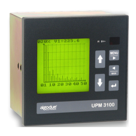
Algodue ELETTRONICA UPM3100 Manual

Installation and Configuration Manual
English
Rev. 007 - 11/09/2006
1IAEUPM310H807
www.algodue.com
UPM3100
Universal Power Meter

1. Model and serial number
Modello e numero di serie
Modell und Seriennummer
Modèle et numéro de série
2. Ordering code
Codice di ordinazione
Bestellungscode
Code pour commande
3. Power supply
Tensione di alimentazione
Stromversorgungsspannung
Tension d’alimentation
4. Measurement range
Campo di misura
Messbereich
Champ de mesure
5. Serial communication protocol
Protocollo di comunicazione seriale
Serielles Kommunikationsprotokoll
Protocole de communication sériel
6. Available RAM memory
Memoria RAM disponibile
Verfügbarer RAM-Speicher
Mémoire RAM disponible
7. Inputs and Outputs
Ingressi e uscite
Ein- und Ausgänge
Entrées et sorties
1
2
3
45
67
Model:
UPM3100
Serial N.:
Z1WHD0003
Code:
ALZAMBA253X2XXG
Aux power supply 65-250Vac / 90-250Vdc, 50 / 60 Hz, 8VA max
Measurement range 600V / 5A rms, 45-65 Hz
RS232/RS485 STANDARD protocol
RAM 2MB
I/O 2 Digital Outputs

1
ENGLISH
TABLE OF CONTENTS
1. INTRODUCTION ..................................... 3
2. GRAPHIC SYMBOLS............................... 4
3. DESCRIPTION......................................... 4
3.1 Recordings ....................................... 5
4. PRELIMINARY CHECKS ......................... 5
5. INSTALLATION ....................................... 6
5.1 Environmental Requirements ........... 6
5.2 Fastening.......................................... 6
6. SAFETY FOR THE CONNECTIONS ........ 7
7. ELECTRICAL CONNECTIONS ................ 8
7.1 Grounding ........................................ 9
7.2 Rear Serial Port................................. 9
7.2.1 RS 232..................................... 9
7.2.2 RS 485..................................... 10
7.3 Front Serial Port ................................ 11
7.4 Digital Outputs.................................. 12
7.4.1 Digital Output Connection....... 12
7.5 Optional Boards................................ 13
7.5.1 Jumper Position....................... 15
7.6 Voltage and Current Inputs .............. 16
7.6.1 Voltage Specifications............. 20
7.6.2 Current Specifications............. 20
7.7 Power Supply ................................... 20
8. CONFIGURATION................................... 21
8.1 Control Panel Description ................ 21
8.2 First Equipment Switching ON ......... 22
8.2.1 Initialization.............................. 22
8.3 General Menu................................... 23
8.4 Setup Menu ...................................... 24
8.4.1 Access .................................... 24
8.5 MAIN PARAMETERS Section............ 25
8.5.1 Current Input Setup................. 26
8.5.2 Voltage Input Setup................. 26
8.6 CLOCK Section ................................ 27
8.7 INPUTS / OUTPUTS Section............. 27
8.7.1 Digital Outputs ........................ 28
8.7.2 Digital Inputs ........................... 29
8.7.3 Analog Outputs ....................... 29
8.7.4 Remarks on Value Programming 30
8.7.5 Fullscale Definition .................. 30
8.7.6 Pulse Value Calculation........... 30
9. USE ......................................................... 31
9.1 Correct Configuration Check............ 31
10. MAINTENANCE....................................... 31
11. TECHNICAL FEATURES ......................... 31

2
ENGLISH

3
ENGLISH
1. INTRODUCTION
This manual provides information on the installation,
configuration and use of the main instrument func-
tions. A second manual with advanced features may
be found on the CD ROM in the box. Both publications
are not intended for general use, but for qualified
technicians. This term means a professional figure
with specific technical qualifications, authorised to
act in accordance with the safety standards relating
to the dangers posed by electric current. This person
must also have basic first aid training and be in
possession of Body Protection Equipment.
WARNING!
It is strictly forbidden for anyone
not satisfying the above mentioned
requirements to install or use the
instrument.
The instrument is made in compliance with the Eu-
ropean Community directives in force, as well as in
compliance with the technical standards implemen-
ting these requirements, as certified by the CE mark
on the instrument and in the publication.
Using the instrument for purposes other than the
intended ones, deducible by the manual content,
is strictly forbidden.
The information contained in this manual may not
be divulged to third parties. Any duplication of this
manual, either partial or total, by photocopying, or
by other means, also electronically, without written
authorization from the manufacturer, violates the terms
of copyright and is punishable by law.
Any brands quoted in the publication belong to the
legitimate registered owners.
NOTE
This manual refers to the complete
instrument version. Some instrument
pages may not be available if the
instrument was purchased without
some functions.
NOTE
“ENH” is the abbreviation for func-
tions or parameters included only in
the Enhanced Package version of the
instrument.

4
ENGLISH
2. GRAPHIC SYMBOLS
In the manual and on the instrument, some instruc-
tions are highlighted by graphic symbols to draw
the reader’s attention to the operational dangers.
The following graphics are used:
DANGER!
This warning indicates the possible
presence of voltage exceeding 1kV
on the marked terminals (even for
short periods).
WARNING!
This warning indicates the possible
occurrence of an event which could
lead to serious damage or consider-
able damage to the instrument if
adequate precautionary measures
are not taken.
ATTENTION!
This warning indicates the possible
occurrence of an event which may lead
to slight damage or material damage
if adequate precautionary measures
are not taken.
NOTE
This warning indicates important
information which must be read care-
fully.
3. DESCRIPTION
The instrument is a panel analyser able to measure
and calculate all the electric parameters of a three
phase system.
Configuration
3-phase analyser, 2MB Flash memory, RTC, RS232
/ RS485 serial port, front RS232 serial port and 4
optional slots. Oscilloscope and profile functions
are included.
The instrument is equipped with a standard serial
port RS232 / RS485 for connection to a Personal
Computer or a printer. Another RS232 serial port is
available on the instrument front panel.
The WINTOOL software, available on internet, allows
to operate directly from a PC and to display the
measured values in numerical format.
For advanced applications refer to DEDALO software
(optional).
The instrument can analyse the harmonic content
up to the 50th order.
All parameters are displayed on a graphic LCD
display.

5
ENGLISH
3.1 Recordings
The instrument can record the readings in the
internal memory. The stored data is downloaded to
a PC and allows to generate consumption profiles,
logged values trends, event and alarm reporting,
cost allocation and reports as well as to identify
critical values.
The instrument records:
Instantaneous values
Min/max values
Harmonics values
DMD power values
Events and alarms (ENH)
Absolute min/max values with time reference(1)
Absolute demand peak values(1)
Energy totalizers(1)
TOU - energy counters
Waveform capture (CPU2 option)
Min/Avg/Max values (CPU2 option)
Voltage drops & peaks (CPU2 option)
(1) This data is always stored.
•
•
•
•
•
•
•
•
•
•
•
•
4. PRELIMINARY CHECKS
NOTE
At box opening, check that there is
no visible damage to the instrument
due to transport.
If the instrument appears damaged, contact the
technical after-sales service.
The box contains:
the instrument
2 fastening screws
1 3-pin female connector (power supply); it differs
from the serial output connector by a keyway (to
avoid accidental connection)
1 3-pin female connector (serial port)
1 4-pin female connector (digital outputs)
1 4-pin female connector (voltage input). Fixed
terminals are provided for the USA version
1 6-pin female connector (current input)
1 CD ROM
the Installation and Configuration Manual
Optional boards
If optional boards are supplied, the following con-
nectors are included.
2 digital output board:
1 4-pin female connector
4 digital output board:
2 4-pin female connectors
2 analog output board:
1 4-pin female connector
LONBUS board
1 2-pin female connector
In case of PROFIBUS and ETHERNET communica-
tion boards, no connector is supplied.
•
•
•
•
•
•
•
•
•
•
•
•
•

6
ENGLISH
5. INSTALLATION
NOTE
The device complies with the 89/366/
EEC, 73/23/EEC standards and subse-
quent updates. However, a magnetic
field and radio interference may be
generated if it is not installed correctly.
Therefore, follow EMC standards for
electromagnetic compatibility.
5.1 Environmental Requirements
The instrument must be installed in a location with
the following features:
no vibrations
indoor area
operational temperature between -15°C and +60°C
(+5°F and +140°F)
storage temperature between -25°C and +75°C
(-13°F and +167°F)
max humidity 80% (no condensation) for up to
31°C (87.8°F), and linear decrease up to 40°C
(104°F)
altitude up to 2000m
In no way, the instrument must be exposed to the
sun rays.
•
•
•
•
•
•
5.2 Fastening
The instrument is for panel mounting.
Size, mm (without terminals):
Panel cutting:

7
ENGLISH
1. Insert the instrument into the hole, by the front
part of the panel.
2. Hold the instrument fixed against the panel, insert
the two fastening accessories into the seats in the
upper and lower part. Tighten the screws until the
instrument is fastened.
ATTENTION!
Tighten the screws gradually until
the instrument is fastened. Do not
overtighten since this might result in
damage to the gasket.
6. SAFETY FOR THE CONNECTIONS
DANGER!
This warning indicates the possible
presence of voltage exceeding 1kV
(even for short periods) on the ter-
minals.
WARNING!
Electrical instrument connections
must be carried out by skilled tech-
nicians who are aware of the risks of
voltage presence. Before making any
connection, check if:
1. the instrument is grounded, following the pro-
cedure indicated in section 7.1
Warning! Each break or separation of the pro-
tection conductor on the inside or outside of
the instrument may jeopardise the operator’s
safety! Intentional breaking of the conductor is
strictly forbidden!
2. no voltage is in the lead wires.
3. the instrument is connected according to the
proper diagram (see section 7.6)
4. the power supply corresponds to the values on
the instrument label.
5. the instrument has been installed in a location
with no vibrations and with a suitable temperature
(see section 5.1).
6. once connected, the terminals are no longer
accessible.
7. the wiring is carried out in accordance with
the standards in force in the country where the
instrument is to be installed.

8
ENGLISH
8. an isolator and two over-current devices (eg.
fuses) are installed between the instrument and
the electrical system.
9. the connections are made respecting the
polarities (the instrument makes bi-directional
measurements)
Important: L1 of the voltage input = L1
of the current input
10. input and output polarities are respected when
voltage or current transformers (PT / CT) are
installed.
11. the connectors are fixed in such a way that they
cannot be accidentally detached.
7. ELECTRICAL CONNECTIONS
The connections are made on the back of the instru-
ment acording to the following order:
European version
USA version

9
ENGLISH
RS232 RS485
WARNING!
Before making any connections, che-
ck if the main control panel switch
is OFF.
1. Digital outputs. See section 7.4
2. Serial port. See sections 7.2 and 7.3
3. Slot available for optional boards. See section 7.5
4. Voltage inputs.See section 7.6
5. Current inputs. See section 7.6
6. Power supply. See section 7.7
7. Grounding. See section 7.1
7.1 Grounding
Connect the grounding cable and tighten the
screw. For direct current application, take care not
to connect the ground with the negative pole of the
power supply.
7.2 Rear Serial Port
The REAR serial port allows a connection with a
printer or a PC.
REAR port can also be configured as RS232 or
RS485 by means of the dip-switches shown in the
following illustration.
CONNECTIONS DIP SWITCHES
PIN 3 2 1 4 3 2 1
RS232 Gnd Tx Rx ON OFF ON OFF
RS485 + - COM OFF ON OFF ON
7.2.1 RS232
The RS232 interface allows connection between just
one instrument and a PC or other device.
The maximum recommended length for a connection
of this type is about 5 m.

10
ENGLISH
For the connection, uses a shielded cable with 3
conductors with a female DB9 or DB25 connector,
according to the following chart.
Terminal DB9F DB25F
Pin 1 - Rx Pin 3 - Tx Pin 2 - Tx
Pin 2 - Tx Pin 2 - Rx Pin 2 - Rx
Pin 3 - GND Pin 5 - GND Pin 7 - GND
Link pins 7 - 8 Link pins 4 - 5
Link pins 1 - 4 - 6 Link pins 6 - 8 - 20
The shield must be grounded only in one point.
7.2.2 RS485
The easiest and cheapest way to connect different
measuring devices in a network is the RS485 serial
line.
The RS485 standard interface allows a multi-
point connection. Between PC and the network,
it is required a Serial RS232 to RS485 Converter
(CV3285M).
If more than 32 instruments are to be connected,
insert a signal repeater (e.g. RPT85).
Each repeater can manage up to 32 instruments.
For the connection among the different modules, use
a cable with a twisted pair and a third wire.

11
ENGLISH
When there are strong electromagnetic distur-
bances, which may affect communication, a shielded
cable should be used.
The Rt termination resistance must be installed on
the PC and the last instrument connected along the
line. Thanks to these resistances, the reflected signal
along the line is reduced.
For a typical telephone pair, Rt can have values from
120 to 150 Ohm.
NOTE
The value of each resistance must not
be lower than 120 Ohm in order to avoid
an overload of line drivers.
The maximum recommended distance for a connec-
tion is 1200 m at 9600 Baud. For longer distances,
lower Baud Rates or low-attenuation cables or signal
repeaters are needed (RPT85).
7.3 Front Serial Port
A RS232 serial port connector is located in the upper
front part of the instrument.
It can be used to read the measurements, program
the instrument and transfer the recorded data to the
processing software (optional, see section 7 in the
Use and Programming manual).
To enable the communication, make the connections
using a standard DB5F-M serial cable, and select
FRONT serial port, as described in section 8.6 of
this manual.
The type of connection, shown in the following
picture, uses a third conductor to ensure that all the
devices on the network have the same reference
level and improve the reliability of communication.

12
ENGLISH
7.4 Digital Outputs
The basic instrument is equipped with two digital
outputs. Additional (input and / or output) boards can
be installed, on request, in the four available slots.
Standard single or multi-conductor cables can be
used for short-distance electrical connections.
For longer distances, the signal and power cables
must not be routed together.
If the signal and power cables cross, keep a 90° an-
gle to minimise the influence of the magnetic field.
ATTENTION!
Before inserting or removing the digital
output connector, make sure that the
instrument is not powered. The power
supply line, the measurement inputs
and any other voltage source must be
electrically disconnected.
7.4.1 Digital Output Connection
The digital outputs can be used, for example, to drive
alarm indicators or for pulse emissions. The needed
function is programmed through instrument setup.
CONNECTOR PINOUT

13
ENGLISH
WIRING DIAGRAM
Maximum withstandable voltage: 50 VDC / 30VAC
Maximum load current: 200 mA
Output on-resistance: 2.5 Ohm typical
WARNING!
The outputs are not protected against
overloads and short-circuits.
7.5 Optional Boards
The basic instrument can be supplied, on request,
with input / output optional boards.
These boards are easy to plug in the available two
slots located on the instrument back side.
A board can be mounted in any available slots.
Available optional boards:
DO board: 2/4 Digital Outputs for alarm tripping
or energy pulse emission.
AO board: 2 Analog Outputs for signal transmis-
sion for external device control.
DI board: 4 Digital Inputs for acquisition of
energy pulses.
Communication boards: LONBUS, PROFI-
BUS, ETHERNET. For further details, see the
relevant manual.
The following procedure describes how to mount
an optional board:
disconnect the instrument supply
disconnect voltage and current inputs
remove the cover of one of the available slot
plug in the optional board with the component
side downwards, paying attention that it has been
properly and completely inserted
close the instrument using the cover supplied
with the I/O board
carry out all the connections again and switch
ON the instrument
update the instrument with the provided pro-
gram
ATTENTION!
Before inserting or removing the I/O con-
nector, make sure that the instrument
is not powered. The power supply line,
the measurement inputs and any other
voltage source must be electrically
disconnected.
•
•
•
•
•
•
•
•
•
•
•

14
ENGLISH
Analog Outputs board
This board is provided with 2 analog outputs. The
value of the output current can be set as 0-20mA
or 4-20mA.
Maximum voltage output: 10V
Maximum load: 300 Ohm
ATTENTION!
The analog outputs are galvanically
isolated from the other parts of the in-
strument, but not between themselves.
See the following picture before making
any connection.
DANGER!
The outputs are not protected against
overloads and short-circuits.
Digital Outputs board
This board can be provided with 2 or 4 galvanically
isolated digital outputs. The following 3 types are
available:
ML type: 50V-300mAAC-DC (optomos)
MH type: 250V-80mAAC-DC (optomos)
RL type: 250V-5A resistive (relay)
•
•
•

15
ENGLISH
Digital Inputs board
This board can be provided with 4 galvanically
isolated digital inputs. The maximum acquisition
frequency is 4 pulses per second.
Maximum frequency: 10Hz
ATTENTION!
The digital inputs are internally pow-
ered, therefore it is necessary to con-
nect a free voltage contact as indicated
in the following picture.
7.5.1 Jumper Position
When two boards, of the same type, are plugged
in the instrument, it is necessary to set the jumper
as follows.
DIGITAL OUTPUTS BOARD
ANALOG OUTPUTS BOARD
*Indicative value

16
ENGLISH
Pict. 1
- 3phases, 4wires, 3CT up to 600V -
Pict. 2
- 3phases, 4wires, 3CT above 600V -
7.6 Voltage and Current Inputs
Connect the voltage inputs by means of the supplied
4-pin connector. For current inputs, use the 6-pin
connector, to be fastened with the provided screws.
The following diagrams show some connection
examples.
WARNING!
Before switching ON the power, check if:
1. the 6-pin current connector is fastened with
screws.
2. in case of bi-directional measurements, the con-
nections are made respecting the polarities to
obtain correct values.
3. the connections are made according to the
diagrams in the following section, respecting the
cyclic order of phases. Important: L1 of the
voltage input = L1 of the current input.
4. input and output polarities are respected when volt-
age or current transformers (PT / CT) are installed.
5. the amperometric signal connector is adequately
fastened to avoid accidental disconnection.
6. a current input is never disconnected without prior
cutting off the load power supply.
If this is not possible, the secondary CT must be
short-circuited.
7. in case of three-phase measurements, all
parameters are shown only with the 3-phase,
4-wires, 3-CT wiring mode. In all other cases the
parameters without sense will not be displayed. By
wiring 3-wire,3-CT (without neutral) it is possible
to connect the N terminal to the ground. In such
a case it is possible to select the wiring 4-wire,
3CT displaying all parameters. It is recommended
an efficient ground to reduce the measuring error.
This suggestion cannot be applied for IT systems,
which are not referred to the ground.

17
ENGLISH
Pict. 3
- 3phases, 3wires, 3CT up to 600V -
Pict. 4
- 3phases, 3wires, 3CT above 600V -
Pict. 5
- 3phases, 3wires, 2CT up to 600V -
Pict. 6
- 3phases, 3wires, 2CT above 600V -

18
ENGLISH
Pict. 9
- 3phases, 1Volt, 3CT up to 600V -
Pict. 10
- 3phases, 1Volt, 3CT above 600V -
Pict. 7
- 3phases, 3wires, 1CT up to 600V -
Pict. 8
- 3phases, 3wires, 1CT above 600V -
Other manuals for UPM3100
2
This manual suits for next models
1
Table of contents
Other Algodue ELETTRONICA Measuring Instrument manuals
Algodue ELETTRONICA
Algodue ELETTRONICA UPM307 User manual

Algodue ELETTRONICA
Algodue ELETTRONICA UPM307 User manual

Algodue ELETTRONICA
Algodue ELETTRONICA UPA20 User manual

Algodue ELETTRONICA
Algodue ELETTRONICA UPM307 User manual

Algodue ELETTRONICA
Algodue ELETTRONICA UPM3100 Owner's manual
Algodue ELETTRONICA
Algodue ELETTRONICA UPM3100 User manual