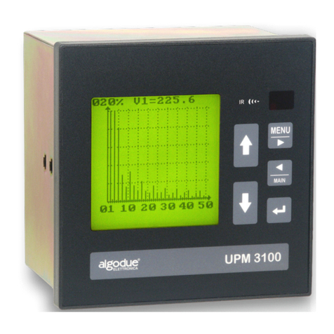
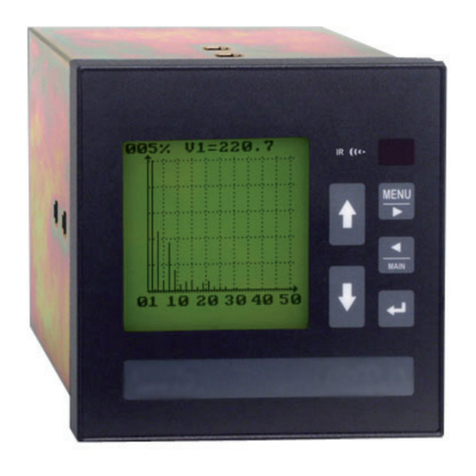
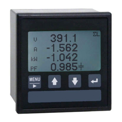
Algodue ELETTRONICA UPM3100 Owner's manual

Use and Programming Manual
English
Rev. 008 - 11/12/2009
1UAUUPM310008
www.algodue.com
UPM3100
Universal Power Meter

ATABLE OF CONTENTS
Use and Programming Manual ENGLISH
TABLE OF CONTENTS
1. INTRODUCTION 1-1
2. SYMBOLS 2-1
3. PRECAUTIONS 3-1
4. USING THE INSTRUMENT 4-1
4.1 General Overview 4-1
4.2 Keypad 4-1
5. MENU 5-1
5.1 Menu Structure 5-1
5.2 Instantaneous 5-3
5.2.1 List of Pages 5-3
5.2.2 Symbols 5-5
5.2.3 Power Factor Compensation 5-6
5.2.4 Displayed Pages 5-7
5.3 Energy Counters 5-9
5.3.1 List of Pages 5-9
5.4 DMD&Peak 5-11
5.4.1 List of Pages 5-11
5.5 Min / Max 5-12
5.5.1 List of Pages 5-12
5.6 Oscilloscope 5-13
5.6.1 List of Pages 5-13
5.7 Harmonics 5-14
5.7.1 List of Pages 5-14
5.7.2 UNDER LIMIT Indication 5-16
5.7.3 Fullscale Setup 5-16
5.8 Profiles 5-17
5.8.1 List of Pages 5-17
5.8.2 Fullscale Setup 5-19

BTABLE OF CONTENTS
Use and Programming Manual ENGLISH
5.9 Utility Setup 5-20
5.9.1 Contrast Adjustment 5-20
5.9.2 Clear Counters 5-20
5.9.3 Clear Min/Max 5-21
5.9.4 Clear Records 5-21
5.9.5 Clear Demands 5-21
5.9.6 Clear DMD Peaks 5-22
5.9.7 Set Default 5-22
5.10 Info 5-23
5.10.1 List of Pages 5-23
6. PROGRAMMING 6-1
6.1 Access and Exit from Setup Menu 6-2
6.1.1 Access 6-2
6.1.2 Exit 6-3
6.2 Page Structure 6-3
6.3 Main Parameters 6-5
6.4 Display 6-7
6.5 Communication 6-8
6.6 Memory 6-9
6.6.1 Files List 6-9
6.6.2 File Information 6-10
6.6.3 New File 6-11
6.6.4 Start/Stop 6-11
6.6.5 Event LOG Mode 6-12
6.6.6 Set Points 6-12
6.6.7 Format 6-13
6.7 Clock 6-14
6.8 Time of Use 6-15
6.8.1 Holidays 6-16
6.8.2 Example of a Tariff Change Programming 6-16

CTABLE OF CONTENTS
Use and Programming Manual ENGLISH
6.9 Input / Output 6-17
6.9.1 Digital Outputs 6-17
6.9.2 Digital Inputs 6-18
6.9.3 Analog Outputs 6-18
6.9.4 Remarks on Value Programming 6-19
6.9.5 Fullscale Definition 6-19
6.9.6 Pulse Value Calculation 6-20
6.10 CPU2 - Power Quality 6-21
6.10.1 VDROP 6-22
6.10.2 MIN/AVG/MAX 6-25
6.10.3 WCAP 6-26
7. TECHNICAL FEATURES 7-1
7.1 Available Options 7-1
7.2 Technical Data 7-2
7.2.1 Electromagnetic Compatibility 7-5
7.3 Performed Measurements 7-6
7.4 Formulas 7-7
7.5 Software 7-8
7.5.1 WINTOOL 7-8
7.5.2 DEDALO 7-8

1-1 INTRODUCTION
Use and Programming Manual
ENGLISH
1. INTRODUCTION
This manual enables the instrument to be installed, configured and used in its main functions. A
second manual with advanced features may be found in the CD ROM in the box.
Both publications are not intended for general use, but for qualified technicians.
By this term, a professional figure is intended with specific technical qualifications, authorised to
act in accordance with the safety standards relating to the dangers posed by electric current.
This person must also have basic first aid training and be in possession of Body Protection equi-
pment.
WARNING!
It is strictly forbidden for anyone who is not in possession of the above
mentioned to install or use the instrument.
The instrument is made in compliance with the European Community directives in force, as well
as in compliance with the technical standards implementing these requirements, as certified by
the EC mark on the instrument and in the publication.
Using the instrument for purposes other than those intended, deducible by the manual content
is strictly forbidden.
The manufacturer reserves the right to make changes to the instrument and/or technical specifi-
cations included in this publication.
It declines all liability for any use of the instrument which is different from that described in this
manual and in the Installation and Configuration Manual, or for the lack /imperfect application of
the reported instructions.
The information contained in this manual may not be divulged to third parties. Any duplication of
this manual, either partial or total, any duplication obtained by photocopying, or by other means,
also electronically, without written authorization from the manufacturer, violates the terms of copyri-
ght and is punishable by law.
The information contained in this manual and in the Installation and configuration manual has
been carefully checked at the time of publication. However, the manufacturer does not accept
liability for any inaccuracy, errors, missing updates, and reserves the right, to make changes to
the instrument and / or documentation without prior notice.
Any brands quoted in the publication belong to the legitimate registered owners.
NOTE
This manual refers to the complete instrument version. Some instrument
pages may not be available if the instrument was purchased without some
functions.
2-1 GRAPHIC SYMBOLS
Use and Programming Manual
ENGLISH
2. GRAPHIC SYMBOLS
In the manual and on the instrument, some instructions are highlighted by graphic symbols to
draw the reader’s attention to the operational dangers.
The following graphics are used:
DANGER!
This warning indicates the possible presence of voltage exceeding 1kV
on the marked terminals (even for short periods).
WARNING!
This warning indicates possible occurrence of an event which could lead
to serious damage or considerable damage to the instrument if adequate
precautionary countermeasures are not taken
ATTENTION!
This warning indicates possible occurrence of an event which may lead
to slight damage or material damage if adequate precautionary measures
are not taken.
NOTE
This warning indicates important information which must be read care-
fully.

3-1
ENGLISH
PRECAUTIONS
Use and Programming Manual
3. PRECAUTIONS
During normal operation the instrument is connected to sources of electrical voltage which are
potentially dangerous for the operator. Voltage is present on the connection terminals of the power
supply wires, on the voltage and current transformers, and on the digital and analog inputs and
outputs.
WARNING!
Any damage following electric shock may result in serious accidents and
cause death.
For this reason, only specifically trained specialized personnel may install, programme and use
the instrument. The definition of “specialized personnel” may be found in Chapter 1.
Once installation has been carried out, the terminals to which the wires are connected, must not
be accessible.
The equipment is in compliance with the 89/366/EEC, 72/23/EEC regulations and subsequent
updates. However a magnetic field and radio interference may be generated if it is not installed
properly. For this purpose, follow the EMC regulations for electromagnetic compatibility and the
instructions in the Installation and Configuration manual.

4-1
ENGLISH
Use and Programming Manual
USING THE INSTRUMENT
Keypad
Display
4. USING THE INSTRUMENT
4.1 General Overview
Infrared port
UP - DOWN keys
Normal display mode
a. Scroll up/down the pages or move the cursor to the available options
Programming mode
a. Move the cursor to the available options
b. Modify the value of the figure (or group of figures) identified by the cursor
MENU key
Normal display mode
a. Pressed for at least 3 seconds, display the General Menu
b. Scroll pages in the OSCILLOSCOPE, HARMONICS and PROFILES functions
Programming mode
a. Pressed together with MAIN key, enter the password
b. Move the selection cursor to the right-hand side figure
c. Pressed for at least 3 seconds, quit the Programming mode
MAIN key
Normal display mode
a. Pressed for at least 3 seconds, toggle the current page as Main Page
b. Pressed together with ENTER key, display the Main Page
c. Scroll pages in the OSCILLOSCOPE, HARMONICS and PROFILES functions
Programming mode
a. Pressed together with MENU key, enter the password
b. Move the selection cursor to the left-hand side figure
4.2 Keypad

4-2
ENGLISH
Use and Programming Manual
USING THE INSTRUMENT
ENTER key
Normal display mode
a. Confirm the selection and display the selected function
b. Pressed together with MAIN key, display the Main Page
Programming mode
a. Confirm the entered selection
b. Confirm the modified values

5-1
Use and Programming Manual
MENU
ENGLISH
5. MENU
To enter the General Menu, press MENU key for at least 3 seconds.
1. INSTANTANEOUS Section 5.2
2. ENERGY COUNTERS Section 5.3
3. DEMAND & PEAK Section 5.4
4. MIN/MAX Section 5.5
5. OSCILLOSCOPE Section 5.6
6. HARMONICS Section 5.7
7. PROFILES Section 5.8
8. UTILITY SETUP Section 5.9
9. SETUP Section 6
10. INFO Section 5.10
5.1 Menu Structure
NOTE
This manual refers to the complete instrument version. Some instrument
pages can be different or disappear if the device was purchased without
some functions.
NOTE
“ENH” is the abbreviation for functions or parameters included only in the
Enhanced Package version of the instrument.
The following page shows the General Menu structure.
To enter any section, move the cursor to the required function and press ENTER key.

5-2
Use and Programming Manual
MENU
ENGLISH
General Menu

5-3
Use and Programming Manual
MENU
ENGLISH
123
56
4
78
5.2 Instantaneous
The pages in this section display the instantaneous values measured by the instrument.
1. Press and hold MENU key for at least 3 seconds. The General Menu
will be displayed
2. Move the highlight bar to INSTANTANEOUS by means of UP and DOWN
keys and press ENTER key
3. Press UP or DOWN key to scroll the available pages
5.2.1 List of Pages
The list of pages depends on the type of programmed wiring mode.
The sequence refers to a 3-phases, 4-wires, 3-current transformers wiring mode.

5-4
Use and Programming Manual
MENU
ENGLISH
910 11
13 14
12
15 16
17 18 19
21 22
20
23

5-5
Use and Programming Manual
MENU
ENGLISH
Description:
1. System values (voltage, current, active power and power factor)
2. System active, reactive and apparent power
3. Line voltages and frequency
4. Phase voltages and phase order
5. Phase and neutral currents
6. Thermal current (ENH)
7. Phase active powers
8. Phase power factors
9. Fresnel diagram and phase power factors
10. Phase apparent powers
11. Phase reactive powers
12. L1 summary
13. L2 summary
14. L3 summary
15. Voltage THD’s
16. Current THD’s (THDAN available only with ENH version)
17. K-Factor (ENH)
18. Voltage and current even & odd THD’s
19. Voltage and current unbalance (ENH)
20. Phase COSφ
21. Fresnel diagram and COSφvalues
22. Power factor compensation calculation
23. User definable page
5.2.2 Symbols
Some pages can contain the following symbols.
Located in the left downside
Located near the PF, COSφ, reactive
power and reactive energy consumption
values
Located near PF, COSφ, reactive power
and reactive energy consumption values
Phase order indication
SYMBOL DESCRIPTION MEANING
MAIN PAGE
LOAD CAPACITIVE
LOAD INDUCTIVE
CW (Clock Wise)
CCW (Counter Clock Wise)

5-6
Use and Programming Manual
MENU
ENGLISH
Exported active power Imported active power
Exported
reactive power
Imported
reactive power
Power factor
(and COSφ)
The figure below shows the geometric representation of active and reactive power and power
factor, in compliance with the EN61268 Standard.
NOTES:
1. The chart refers to the current vector “I” (on the RH-side).
2. The direction of the voltage vector “V” changes depending on the phase displacement angle Ø.
3. The displacement angle Ø between voltage “V” and current “I” is positive in the trigonometric
expression (counter-clockwise).
5.2.3 Power Factor Compensation
This function calculates the power of the PF compensation capacitors (var), which is necessary
to raise the measured COSφto the requested value (Target).
1. Press ENTER key to set a new Target value
2. Choose one of the available values using UP and DOWN keys (the
available values are: 0.800; 0.850; 0.900; 0.910; 0.920; 0.930; 0.940;
0.950; 0.960; 0.970; 0.980; 0.990; 1.000)
3. To confirm the selected value press ENTER key
Depending on the selected target value and the Instantaneous COSφvalues, in the “var” column
the instrument calculates the reactive power to be compensated.

5-7
Use and Programming Manual
MENU
ENGLISH
3-4-3
3-3-2
1-ph
System voltage V
System current A
System power factor PF
System active power W
System reactive power var
System apparent power VA
Frequency HZ
Neutral current AN
Phase reversal -->
L-N voltage phase 1 V1
L-N voltage phase 2 V2
L-N voltage phase 3 V3
L-L voltage line 12 V12
L-L voltage line 23 V23
L-L voltage line 31 V31
Phase 1 current A1
Phase 2 current A2
Phase 3 current A3
Phase 1 thermal current A12S
Phase 2 thermal current A22S
Phase 3 thermal current A32S
Voltage unbalance Vub%
Current unbalance Aub%
Phase 1 power factor PF1
Phase 2 power factor PF2
Phase 3 power factor PF3
Phase 1 COSφCOSφ1
Phase 2 COSφCOSφ2
Phase 3 COSφCOSφ3
Description Var.
Wiring mode
ENH
5.2.4 Displayed Pages
The pages and the values displayed in the INSTANTANEOUS section can be different as they
depend on the type of programmed wiring mode. See the following table.
3-3-3
3-3-1
3-1V-3
1-3-2

5-8
Use and Programming Manual
MENU
ENGLISH
Phase 1 active power W1
Phase 2 active power W2
Phase 3 active power W3
Phase 1 reactive power var1
Phase 2 reactive power var2
Phase 3 reactive power var3
Phase 1 apparent power VA1
Phase 2 apparent power VA2
Phase 3 apparent power VA3
Phase 1 voltage THD THDV1
Phase 2 voltage THD THDV2
Phase 3 voltage THD THDV3
Phase 1 current THD THDA1
Phase 2 current THD THDA2
Phase 3 current THD THDA3
Neutral current THD THDAN
Phase 1 voltage THDeven THDeV1
Phase 2 voltage THDeven THDeV2
Phase 3 voltage THDeven THDeV3
Phase 1 current THDeven THDeA1
Phase 2 current THDeven THDeA2
Phase 3 current THDeven THDeA3
Phase 1 voltage THDodd THDoV1
Phase 2 voltage THDodd THDoV2
Phase 3 voltage THDodd THDoV3
Phase 1 current THDodd THDoA1
Phase 2 current THDodd THDoA2
Phase 3 current THDodd THDoA3
Phase 1 K-Factor K1
Phase 2 K-Factor K2
Phase 3 K-Factor K3
3-4-3
3-3-2
1-ph
Description Var.
Wiring mode
ENH
3-3-3
3-3-1
3-1V-3
1-3-2

5-9
Use and Programming Manual
MENU
ENGLISH
5.3 Energy Counters
The pages of this section display the energy counters.
1. Press and hold MENU key for at least 3 seconds. The General Menu
will be displayed
2. Move the highlight bar to ENERGY COUNTERS by means of UP and
DOWN keys and press ENTER key
3. Press UP or DOWN key to scroll the available pages
5.3.1 List of Pages
The following pages describe the instrument energy counters.
Three types of counters are available:
• Main energy counters
• TOU - Time of use counters
• Digital inputs counters (optional)
Main Energy Counters
1. Imported energy
• active energy [kWh]
• lagging reactive energy [kvarh]
• leading reactive energy [kvarh]
• lagging apparent energy [kVAh]
• leading apparent energy [kVAh]
2. Exported energy
• active energy [kWh]
• lagging reactive energy [kvarh]
• leading reactive energy [kvarh]
• lagging apparent energy [kVAh]
• leading apparent energy [kVAh]

5-10
Use and Programming Manual
MENU
ENGLISH
1234
5678
9101112
TOU - Time Of Use
The instrument manages TOU energy counters divided into three programmable bands
(Rates). There are 120 time of use counters, divided as follows:
• 5 counters for imported energy and 5 counters for exported energy
• 12 pages for separate counters for each time period and the corresponding rate (band)
Digital Inputs Counters (optional)
If the DI4-TR board is plugged-in (4 digital inputs, optional), another page is
available. The pulses counted by each input is displayed on this page.
A different measuring unit and multiplying factor can be assigned to each
input.

5-11
Use and Programming Manual
MENU
ENGLISH
1234
5
5.4 Demand&Peak
The pages of this section display the demand and demand peak values.
1. Press and hold MENU key for at least 3 seconds. The General Menu
will be displayed
2. Move the highlight bar to DEMAND&PEAK by means of UP and DOWN
keys and press ENTER key
3. Press UP or DOWN key to scroll the available pages
5.4.1 List of Pages
The list of pages depends on the type of programmed wiring mode (see table in section 5.2.4).
The sequence refers to a 3-phases, 4-wires, 3-current transformers wiring mode.
DEMAND VALUES PAGES (DMD)
List of demand values pages:
1. Phase 1, 2, 3 and neutral current
2. System active and apparent power. Ratio between DMD active
power and DMD apparent power
3. System current, lagging reactive power, leading reactive power
DEMAND PEAK VALUES PAGES (DMD-Peak)
List of DMD peak values pages, with date and time reference:
4. Phase 1, 2, 3 and neutral current
5. System active power, apparent power, lagging reactive power,
leading reactive power
Other manuals for UPM3100
2
Table of contents
Other Algodue ELETTRONICA Measuring Instrument manuals

Algodue ELETTRONICA
Algodue ELETTRONICA UPA20 User manual

Algodue ELETTRONICA
Algodue ELETTRONICA UPM307 User manual

Algodue ELETTRONICA
Algodue ELETTRONICA UPM3100 User manual

Algodue ELETTRONICA
Algodue ELETTRONICA UPM307 User manual

Algodue ELETTRONICA
Algodue ELETTRONICA UPM307 User manual

Algodue ELETTRONICA
Algodue ELETTRONICA UPM3100 Manual