Algodue ELETTRONICA UPM3100 User manual

EN50160
Energy quality Analysis
English
Rev. 01 - 2003
UPM 3100
Universal Power Meter
1UAMVMAX3101

AGeneral contents
EN50160 - Energy analysis
ENGLISH
UPM3100
General contents
GENERAL CONTENTS ........................................................A
CHAPTER 1 INTRODUCTION................................................................1-1
CHAPTER 2 GRAPHIC SYMBOLS.........................................................2-1
CHAPTER 3 PRECAUTIONARY MEASURES ....................................... 3-1
CHAPTER 4 DESCRIPTION ...................................................................4-1
4.1 FUNCTIONING ..........................................................4-2
4.1.1 MIN/AVG/MAX .........................................................4-2
4.1.2 VDROP.....................................................................4-3
CHAPTER 5 DISPLAYEDDATA ............................................................. 5-1
5.1 INFOPAGE...............................................................5-1
CHAPTER 6 PROGRAMMING................................................................ 6-1
6.1 VDROP .....................................................................6-2
6.1.1 DIGITAL OUTPUT....................................................6-3
6.2 MIN/AVG/MAX ............................................................6-4
CHAPTER 7 TECHNICAL SPECIFICATIONS........................................7-1
CHAPTER 8 WINTOOL SOFTWARE...................................................... 8-1
8.1 PROGRAMMING .......................................................8-1
8.2 VDROP SETUP ........................................................ 8-2
8.2.1 DIGITAL OUTPUT....................................................8-4
8.3 MIN/AVG/MAX ............................................................8-5
8.4 DOWNLOAD ............................................................8-7

1-1 Introduction
EN50160 - Energy analysis
ENGLISH
UPM3100
1. Introduction
ThisManualisnotintendedforgeneraluse,butforqualifiedtechnicians.
Thistermindicatesaprofessionalandskilledtechnician,authorisedto
act in accordance with the safety standards relating to the dangers
posed by electric current.
Thispersonmustalsohavebasicfirstaidtrainingandbeinpossession
of suitable Personal Protective Equipment.
WARNING!
It is strictly forbidden for anyone who does not have the
above-mentioned features to install or use the device.
The device complies with the European Union directives in force, as
wellaswiththetechnicalstandardsimplementingtheserequirements,
as certified by the EC mark on the device and on this Manual.
Usingthetoolforpurposesotherthanintendedones,deducible by the
manual content, is strictly forbidden.
The manufacturer reserves the right to modify the device and/or
technical specifications included in this Manual.
TheManufacturershallnotshoulderanyresponsibilityforanyuseofthe
instrument which is different from that illustrated in this manual and in
the
Installationandconfigurationmanual
,orfornon-/imperfectapplication
of the specified instructions.
Theinformationhereincontainedshallnotbesharedwiththirdparties.
Any duplication of this manual, either partial or total, not authorised in
writingbytheManufacturerandobtainedbyphotocopying,duplicating
orusinganyotherelectronicmeans,violatesthetermsofcopyrightand
is punishable by law.

1-2 Introduction
EN50160 - Energy analysis
ENGLISH
UPM3100
The information contained in this manual and in the Installation and
ConfigurationManualwascarefullycheckedatthetimeofpublication.
However,theManufacturerdoesnotacceptliabilityforanyinaccuracy,
errors,missingupdates,andreservestherighttomodifythedeviceand
/ or documentation without prior notice.
Anybrandsquotedinthepublicationbelongtothelegitimateregistered
owners.
NOTE
This Manual refers to the complete instrument version.
Some displays may not be available if the instrument was
purchased without some functions.

2-1 Graphic symbols
EN50160 - Energy analysis
ENGLISH
UPM3100
2. Graphic symbols
Some instructions in the Manual and on the device are highlighted by
graphic symbols to draw the reader’s attention to the operational
dangers.
The following graphic symbols are used:
DANGER !
This warning indicates the possible presence of voltage
higher than 1kV on the marked terminals (even for short
periods).
WARNING!
This warning indicates the possible occurrence of an event
whichmaycauseaseriousaccidentorconsiderabledamage
to the device if suitable precautionary countermeasures
are not taken.
ATTENTION!
This warning indicates the possible occurrence of an event
which may cause a light accident or damage to the device
if suitable precautionary countermeasures are not taken.
NOTE
This warning indicates important information which must
be read carefully.

3-1 Precautionary measures
EN50160 - Energy analysis
ENGLISH
UPM3100
3.PRECAUTIONARY
MEASURES
In standard operation mode, the instrument is connected with power
sources that are potentially dangerous for operators. The connecting
terminals of the power supply cables, the voltage and current
transformersandthedigitalandanaloginputsandoutputsarepowered.
WARNING!
Electrocution may cause serious accidents and eventually
fatal injuries.
Thisiswhytheinstrumentmustbeinstalled,programmedandusedby
skilled and trained technicians. See chapter 1 for the definition of
“skilled technician”.
Aftertheinstallation,theterminalstowhichcablesareconnectedmust
be inaccessible.
Theequipmentcomplieswiththe89/366,73/23regulationsandfollowing
amendments. However, if not properly installed, it may generate a
magneticfieldandradiointerference. TheEMCregulationsonelectro-
magneticcompatibilityandtheinstructionscontainedinthe
Installation
and Configuration
Manual must be complied with.

4-1 Description
EN50160 - Energy analysis
ENGLISH
UPM3100
4.DESCRIPTION
The device equipped with the CPU2 option assures the continuous
sampling of the measured values. The CPU2 can store the following
data in its RAM:
- Any detected voltage anomalies (VDROP);
- Minimum, Average and Maximum values of 10 variables, selected
among those measured by the device.
ThedatastoredintheCPU2cardRAMcanbetransferredtoaPersonal
Computer,bymeansoftheDEDALOandWINTOOLsoftware,forlater
analysis.
Thefunction
MIN/AVG/MAX
allowstocalculateandstoretheminimum,
average and maximum values from a selectable variable group by a
programmable time interval (from 1 to 999s).
With the
VDROP
option the instrument can measure the following
voltage faults: fast voltage variation, voltage drop, short voltage
interruption,longvoltageinterruption,overvoltage.

4-2 Description
EN50160 - Energy analysis
ENGLISH
UPM3100
TAV = 0,1 - 9999 S
4.1 FUNCTIONING
4.1.1 MIN/AVG/MAX
Thisfunctionassuresthecontinuoussamplingofthevariablesandcan
be used to record the minimum, medium and maximum values of the
programmedvariableinordertocarryoutthemainsqualityanalysisin
compliance with the EN50160 norms.
Attheendofanyprogrammedintegration interval(from1to999s),the
minimum and maximum RMS values and the corresponding period
reference (TRMS) are recorded.
The RMS value is calculated for any period (TRMS); the wave number
per period (TRMS) can be set at a number ranging from 1 to 99 (see
chapter 3.2). Thanks to this value the device reaction time, for the
calculation of the RMS value, can be changed.
Pict 4.1.1 - Continuous sampling for the MIN/AVG/MAX recording
MIN/AVG/MAX
recording
TRMS = 1 - 99 waves
TAVG = 1 - 999 S
MIN/AVG/MAX
recording

4-3 Description
EN50160 - Energy analysis
ENGLISH
UPM3100
4.1.2 VDROP
IncompliancewiththereferencenormEN50160,thefollowingvoltage
anomalies can be measured and recorded thanks to the VDROP
record:
-Fastvoltage variation
Fast increase or decrease of voltage up to 10% of the nominal
voltage.
-Voltagedrop
Suddendecreaseofvoltagefrom90%to1%ofthenominalvoltage,
afterashorttimethevoltageresumes.Avoltagedropconventionally
lasts from 10 ms to 1 minute.
-Shortvoltageinterruption
Inthisconditionthevoltageislowerthan1%ofthenominalvoltage,
for less than 3 minutes.
-Longvoltageinterruption
Inthisconditionthevoltageislowerthan1%ofthenominalvoltage,
for more than 3 minutes.
-Overvoltage
Temporary overvoltage with line frequency.
Themeasurementsaretakenbetweenphaseandneutralindependently
on each of the three phases, and only using direct insertion mode (the
full-scale of the instrument is around 433V - 750V between one phase
and the other).
That is valid for TT or TN system complying with the IEC364 norm .
There are two thresholds, one is greater (high threshold) than the
voltage nominal value and the other one is lower (low threshold), they
can be set independently.
For each phase the instrument calculates each 10 msec the RMS
values and compares with the preset thresholds.
Ifoneofthepresetthresholdsisexceeded,theinstrumentstartssaving
a set of data on the event.
Ifthedevicehasthedigitaloutputoption,theoccuredvoltageanomaly
can be signalled on the output.
It is a mono-stable operation, i.e. when the event occurs, the output is
enabled for a period of time to be set at 1 to 10 seconds.
Theacquisitionofvoltagefaultsmaybeprogrammedwithtwodifferent
modes of operation:
- With fixed reference voltage.
- With variable reference voltage.

4-4 Description
EN50160 - Energy analysis
ENGLISH
UPM3100
ACQUISITION WITH FIXED REFERENCE VOLTAGE
In this mode of operation, the reference voltage used for threshold
values calculation is fixed and as the same value of preset nominal
voltage (Pict. 1.3.2).
Thehighandlowthresholdvaluesareexpressedaspercentagesofthe
reference value.
Thevalues of the thresholds arefixed for all the time of measurement.
ACQUISITION WITH VARIABLE REFERENCE VOLTAGE.
Inthevariablemodeofoperationthereferencevoltage,thatisusedfor
calculationofthresholds,iscalculatedautomaticallyby theinstrument
(Pict. 1.3.3).
The measured value of each phase is integrated along a time interval
that may be programmed from 1 to 99 minutes.
The measurements made during the voltage anomaly are not used to
recalculate the reference value.
Theintegratedvalueisusedattheendoftheprogrammedtimeinterval
as a reference for the thresholds of the following time interval.
The high and low thresholds are always expressed as percentages of
the reference value.
With this mode of operation slow changes of voltage may be tracked
and only short-lasting events highlighted.
Pict. 4.1.2 Acquisition with fixed nominal value. High threshold exceeded.
RMS value calculated every 10ms.
Pict. 4.1.3 - Acquisition with variable nominal value. Low threshold exceeded.

5-1 Displayed data
EN50160 - Energy analysis
ENGLISH
UPM3100
5. DISPLAYED DATA
5.1 INFO PAGE
When the CPU2 option is included, on the LCD graphic display an
additional info PAGE shows the recordings information.
VDROP RECORDING
Onthepagethevaluesofphase1,2and
3aredisplayedalternatively.
-Timeintervalofintegrationforcalculation
of the reference voltage
(if IT=00 Vr = Vnom is set) [min]
- Voltage reference value (Vr) [V]
- Low threshold [V]
- High threshold [V]
- Total number of events and number of
recorded events divided for each line
-RAM occupied (1MB Max)
MIN/AVG/MAX RECORDING
The page shows the storage data:
- Selected variables.
-RMSvaluecalculationtime(expressed
in periods).
- Recording type and state (“ON”=
enabled, “OFF”= disabled, “WAIT”=
pending recording with postponed start,
waiting for the end of the set time).
CPU2-VDROP L1
IT= 02min. VAR.
Vr= 219.96 V
HT= 230.35 V
LT= 210.00 V
EV.: TOTAL MEMO
V1: 0011 0011
V2: 0011 0011
V3: 0011 0011
RAM: 21.020 kB
Pict. 5.1.1 - Configuration of the
instrument
Pict. 5.1.2 - Configuration MIN/
AVG/MAX
CPU2-MIN/AVG/MAX
Variables:
V1-V2-V3-A1-A2-A3-
P-P1-P2-P3
T. RMS = 01 waves
T. AVG = 010 s
Rec.(STACK) =ON

6-1 Programming
EN50160 - Energy analysis
ENGLISH
UPM3100
6.PROGRAMMING
IftheCPU2isselectedintheprogramming
page of the device, the displayed page
allows the user to select the VDROP or
MIN/AVG/MAXrecording.
When moving from one recording mode
toanother,theselectionconfirmationpage
is displayed:
CPU2
VDROP
MIN/AVG/MAX
Previous
Pict. 6.0.1 - CPU2 recording
selection
Pict. 6.0.2 - confirmation page
Change CPU2
mode?
YES

6-2 Programming
EN50160 - Energy analysis
ENGLISH
UPM3100
6.1 VDROP
Page for programming the recording of
voltagefaults,whentheVDROPoptionis
included.
-Vnom (%FS)
This value is expressed as a percentage
oftheprogrammedfullscalevalue(433V).
Thenumberjustbelowistheactualvalue,
which is calculated automatically.
Byprogrammingwithfixednominalvalue,
it corresponds to the reference value
(Vref).
By programming with variable nominal value, it corresponds to the
reference value only for the first considered period.
- HT (+%Vn)
High threshold. Over this value overvoltage is recorded.
This value is expressed as a percentage variation of the programmed
reference value (ranging from +1% to +99%). The number just below
expresses the actual value, which is calculated automatically.
- LT (-%Vn)
Low threshold. Below this value voltage drop or line interruption are
recorded.
This value is expressed as a percentage variation of the programmed
reference value (ranging from -1% to -99%.). The number just below
expresses the actual value, which is calculated automatically.
- In. Time
Integration time interval for calculation of voltage in the variable mode
(programmable 0-99 min.) The variable mode is enabled by any non-
zero setting the integration time. If the value is 00 the fixed mode is
selected (see section 1.2).
- Erase RAM
Displays the cancellation confirmation box for the file stored in the
CPU2RAM.
- Previous
Goes back to the CPU2 storage selection page.
Pict. 6.1 - VDROP programming
CPU2-VDROP
Vnom(%FS) %050.81
0220.0 V
HT(+%Vn) %005.00
0231.0 V
LT(-%Vn) %004.00
0211.2 V
In.Time 00 min
Erase RAM
Previous

6-3 Programming
EN50160 - Energy analysis
ENGLISH
UPM3100
6.1.1 DIGITAL OUTPUT
If the digital option is installed, voltage
dropsmaybesignaledthroughthedigital
output.
Theoperationismonostable,i.e.afterthe
eventtakesplacetheoutputison(closed)
foraprogrammabletimeintervalranging
from 1 to 10 seconds.
- Var.
Select VDROP.
- Mode.
Pulse fixed.
- Delay
Pulse width: 1-10s.
- Hyst.
Not programmable: not significant.
- Set
Not programmable: not significant.
- Previous
Goes back to the
IN/OUT
page.
To quit the Main Setup menu, press for at least 3 seconds.
A page requesting confirmation will be displayed.
Pict. 6.1.1 - Digital Out page
DIGITAL OUT 1
Var. VDROP
Mode PULS
Delay 05
Hyst. 00
Set %000.00
000.00
Previous

6-4 Programming
EN50160 - Energy analysis
ENGLISH
UPM3100
6.2 MIN/AVG/MAX
- Parameters
The values which can be stored are
sequentially shown;
- select parameters;
- storage enabled/disabled.
Note: max. 10 variables can be
simultaneously stored.
- Time AVG
Integrationtimeinsecondsforthecalculationofthemediumvalue;itis
also the storage interval of the minimum and maximum values.
The value to be programmed is included in the 1-999 second range.
If the T.Intergr. value is set at 600 (10 minutes) and the device keeps
recordingforatleastoneweek,thedevicewillrecordallthenecessary
informationfortheanalysisanddetectionofthesupplyvoltagechanges,
in compliance with the EN50160, thanks to the Multigraph software.
- Time RMS
Number of periods for each AVG time; an RMS value is calculated for
anyperiod.
The value can be set at 1-99, but it cannot exceed half of the periods
included in the integration time at the measurement frequency.
Ex:
T.AVG: 3 sec.
Frequency:50Hz —> Periodduration1/50=0.02s
T.RMS(max)=3/(2*0.02)=75(max.numberofprogrammableperiods)
- Memo Type
Selects the RAM storage method of the minimum/medium/maximum
values as follows:
-FIFO -storage of the latest data, by overwriting the old data;
-STACK -data storage until the RAM is full.
Note: in case of STACK storage, the “OFF” message is displayed on
the “State” bar of the “INFO” page (see chapter 2.1) when the RAM is
full.
CPU2-MIN/AVG/MAX
Param. V1 YES
T.AVG 600 s
T.RMS 10 waves
MemoType FIFO
Rec.Delay 09:30
Erase RAM
Previous
Pict.6.2.1 - MIN/AVG/MAX setup

6-5 Programming
EN50160 - Energy analysis
ENGLISH
UPM3100
- Recording Delay
Storage delayed start, expressed in hours and minutes.
Programmable range from 00:00 to 23:59.
This parameter can be programmed only after selecting the STACK
storage mode.
- Erase RAM
Displays the cancellation confirmation box for the file stored in the
CPU2RAM.
- Previuos
Goes back to the CPU2 storage selection page.

7-1 Technical specifications
EN50160 - Energy analysis
ENGLISH
UPM3100
7. TECHNICAL
SPECIFICATIONS
VDROP:
Connection: 4 connection wires with neutral + single
phase.
Voltage: 433 VAC max. L-N (750 VAC L-L).
Measurement mode: continuoussamplingofthethreephases
RMS value is calculated every 10 ms.
Measurement frequency: 45-65 Hz.
Minimum threshold value: from +1to +99%ofVn(from 5to430V).
Maximum threshold value: from -1 to -99% of Vn (from 5 to 430 V).
MIN/AVG/MAX:
Insertion: any available insertion drawings.
Measurement method: continuous sampling on three phases.
Recording frequency: programmable, from 1 to 999 s.
RMS calculation frequency: programmable, from 1 to 99 waves.
Measurement frequency: from 45 to 65 Hz.
DIGITAL OUTPUT:
Digital output, programmable from 1 to 10 seconds.

7-2 Technical specifications
EN50160 - Energy analysis
ENGLISH
UPM3100
MEMORY:
Values which are recorded for each event:
VDROP
- Date and time of fault start.
- The fault type: vdrop or overvoltage.
- The phase (L1-N, L2-N, L3-N).
- The minimum or the maximum values measured.
- The fault duration .
- The reference value.
- The minimum and maximun threshold.
- The 100 values measured before the fault (calculated each
halfperiod).
- The 100 values measured after the fault (Post Trigger).
- The average value of the 100 values measured before the fault.
- The integration time.
MIN/AVG/MAX
- Recording date and time;
- Minimum, medium and maximum value of any selected variable.

8-1 Wintool Software
EN50160 - Energy analysis
ENGLISH
UPM3100
8. WINTOOL SOFTWARE
TheWINTOOLsoftwareis supplied with theinstrument.Thissoftware
detects automatically if the CPU2 option is included. It is used to
program the instrument and transfer the data to the PC.
8.1 PROGRAMMING
ToentertheCPU2programmingwindowselecttheproperbuttoninthe
instrument set up window:

8-2 Wintool Software
EN50160 - Energy analysis
ENGLISH
UPM3100
8.2 VDROP SETUP
Thefollowingboxisdisplayedwhen isselected:
- EN 50160 Setup
Activatingthisfunction,thelowestthresholdandtheintegrationtimeare
programmed automatically to the standards. The field which can be
modified contain values not specified in the standard.
- Nominal Voltage [%FS]
Nominalvalueof the voltageinpercentage of the fullscale.On its side
the real value is automatically calculated.
Byprogrammingwithfixednominalvalue,itcorrespondstothereference
value(Vref).
By programming with variable nominal value, it corresponds to the
reference value only for the first.
- Low Threshold [-%Vn]
Low threshold. Below this value voltage drop or line interruption are
recorded.
This value is expressed as a percentage variation of the programmed
referencevalue(rangingfrom-1%to-99%.).Thenumberitssideisthe
actual value, which is calculated automatically.
Other manuals for UPM3100
2
Table of contents
Other Algodue ELETTRONICA Measuring Instrument manuals
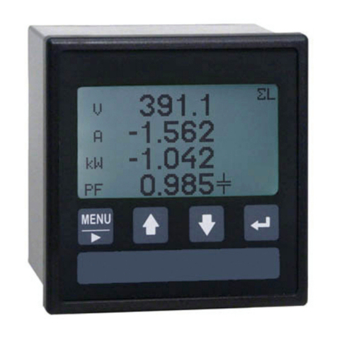
Algodue ELETTRONICA
Algodue ELETTRONICA UPM307 User manual
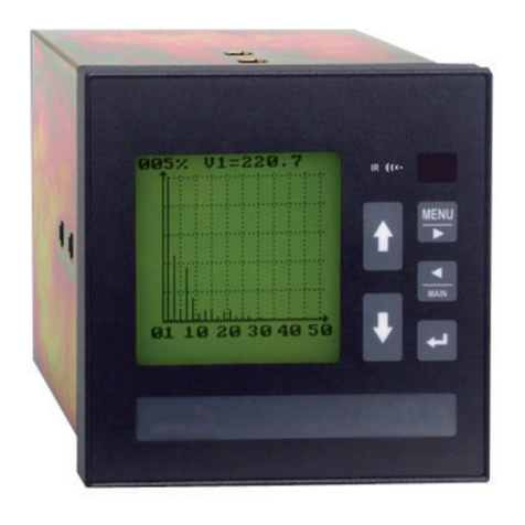
Algodue ELETTRONICA
Algodue ELETTRONICA UPM307 User manual

Algodue ELETTRONICA
Algodue ELETTRONICA UPA20 User manual

Algodue ELETTRONICA
Algodue ELETTRONICA UPM307 User manual

Algodue ELETTRONICA
Algodue ELETTRONICA UPM3100 Manual

Algodue ELETTRONICA
Algodue ELETTRONICA UPM3100 Owner's manual
Popular Measuring Instrument manuals by other brands

Ametek
Ametek AMEVision 3050-OLV user manual

Kroeplin
Kroeplin C0 Series user manual

BCID Bio-Science
BCID Bio-Science CI-203 Operation manual

Siemens
Siemens SITRANS FX330 operating instructions

Laguna Tools
Laguna Tools PL1220 owner's manual

Endress+Hauser
Endress+Hauser Proline Prosonic Flow 93 Function manual