ALIBI ALI-TP1135R User manual

1www.observint.com ALI -T P1135R _CQ
190903
Switch
button*
Cap for
switch
button
12 Vdc power in
HD video BNC connector
* Switch button: The switch button is reserved for future use.
Camera drop cable connectors
What’s in the box
• Camera assembly
• Mounting hardware
• This instruction guide
• Drill template
Tools you need
To install the camera, you will need:
• 12 Vdc power source. See Specications for wattage requirement.
• Phillips type screwdriver
• Tools and additional fasteners (may be required) for mounting the camera
• Video and power extension cable
• Caulk or other exterior sealant
Installation
Before installation:
• Make sure that the device is in good condition and all the assembly parts are included.
• Check the specication of the products for the installation environment.
• Make sure that the wall or the ceiling is strong enough to withstand three (3) times the weight of the
camera and brackets used.
• To avoid re or shock hazard, use only UL listed power supplies. Verify that the power supply will
provide the rated voltage and wattage for the camera. See the Specications section.
During installation:
• Camera Lens: Handle the camera carefully to prevent scratching or soiling the lens. If the lens or IR
array shield becomes soiled, clean it only with approved products. See the Cleaning section.
• Power supply: Camera drop cable: The camera drop cable includes two connectors:
—Video BNC connector: For transmission of the TVI / AHD / CVI video signal across a coax (75 Ω)
extension cable.
—Power connector: When applying 12 Vdc power, observe the power polarity. See the drop cable
photo above for the connector polarity conguration.
Step 1. Mounting the camera
These cameras can be mounted on a wall or ceiling that has sucient strength to support it. The video/
power drop cable from the camera can be routed either through mounting surface or through a cable guide
on the edge of the mounting base.
NOTE
This camera can be installed using a pendant mounting bracket or junction box. Please refer to the
instructions provided with those accessories for special considerations when installing the camera
with them.
1. Determine and acquire the best kind of fasteners for securing the camera to the mounting surface.
The mounting hardware provided with the camera is appropriate for many surfaces.
2. To release the enclosre from the camera, loosen the retention tab hold down screw, and then slide
the tab away from the enclosre. It isn’t necessary to remove the screw. See below.
ALI-TP1135R 5 MP HD-TVI
Outdoor Turret Camera
Quick Installation Guide
The ALIBI ALI-TP1135R HD-TVI turret camera features:
• 5.0 megapixel progressive scan CMOS
• 2560 x 1944 resolution
• 2.4 mm xed lens oers horizontal FOV of 110°
• 0.01 Lux, 0 Lux with IR
• Smart IR up to 65 ft IR distance
• Up the Coax (UTC) for easy OSD control
• IP67 weather-rated with -40°F – 140°F operating temperatures
• Compatible with ALI-AA1 outdoor pole mount adapter, ALI-AA2 outdoor corner mount adapter for
ALI-AB1 and ALI-AB2, ALI-AB1, ALI-AB2, ALI-AB3 ceiling pendant mount bracket, ALI-AF4 ange
adapter, ALI-AJ1 round junction box, ALI-AJ6 mini junction box
Cable
channel
Enclosure
Camera
module,
turret
Mounting
base
Lens IR LED
Enclosure
retention
tab (3)
Tab, and
hold down
screw
Hole for
mounting
screw (3)
Mounting plate features (camera mounting surface)

2www.observint.com
Retention tab over
lip of enclosure
Enclosure released
3. Separate the enclosre and the camera module from the mounting plate.
4. Using the drill template or the mounting plate, mark the holes for the mounting screws.
5. Drill holes for the screws that anchor the base to the mounting surface. The mounting hardware
provided is appropriate for most surfaces. However, depending on the surface material and strength,
more appropriate fasteners may be required.
6. Drill a 3/4” hole through the mounting surface for the camera drop cable, if necessary.
7. If using wall inserts for the mounting screws, install the wall inserts at this time.
8. Attach the mounting plate the surface using the appropriate fasteners. If the camera drop cable will
route through a cable guide, lay the cable in the guide before tightening the mounting screws.
Cable channel (2)
9. Route the drop cable through the hole, and then adjust the camera on the mounting plate to point
at your surveillance target. Ensure that the “UP” orientation mark on the camera module (see photo
above) is up.
10. Place the enclosre over the camera module such that the lip of the enclosre is under the two xed
retention tabs.
11. Position the retention tab so that it is over the lip on the enclosre, and then tighten retention screw
until it is snug. Do not tighten the screw at this time.
12. Connect the camera drop cable to video and power extension cables.
13. Connect the other end of the video extension cable to a video monitoring device, such as a
compatible recorder.
NOTE
Drop cable connectors are not waterproof. Seal these connectors as needed to block
moisture and other contaminants. Contamination of the drop cable connectors is
considered an installation error and voids the warranty.
Use caulk or exterior sealant to ll holes drilled in any exterior surface.
14. Connect the other end of the power extension cable to a 12 Vdc power source. Observe the polarity
of the cable shown in the photo on page 1 of this guide.
Step 2. Camera adjustments
1. Apply power to the camera.
2. Verify that video from the camera can be seen on a monitor.
3. Screw the cap onto the switch button drop cable to protect the switch from contamination.
4. While observing video from the camera, adjust camera direction (pan), tilt and rotation to center
the camera on your surveillance target.
Rotation
adjust
0° ~ 360°
Pan adjust
0° ~ 360°
Tilt adjust
0° ~ 75°
5. While holding the camera module and enclosre in place, tighten the retention tab hold down screw
to secure the enclosre.
Step 3. Open the OSD menu
The On Screen Display (OSD) provides conguration options for rening the performance of the camera.
It also can be used to block sensitive portions in the eld of view (Privacy). You can open the OSD menu
system from either the ALIBI recorder Live View display (QVR) or through remote login to the ALIBI
recorder.
Opening the OSD Menu through the QVR
To open the OSD menu on the QVR monitor:
1. Open the QVR Live View screen, and then click inside the screen where the PTZ camera video image
is displayed. See below.
2. Click the PTZ Control icon in the Quick Setting Toolbar. The PTZ camera Live View window will
expand to full screen and the pop-up window shown below will open.
Menu icon
© 2019 Observint Technologies. All rights reserved.

3www.observint.com © 2019 Observint Technologies. All rights reserved.
3. In the PTZ Control panel pop-up window, click the Menu icon on the Conguration line.
4. Drag the PTZ Control window to a position where it doesn’t cover the OSD menu (such as the left
side).
NOTE
The PTZ Control window direction buttons and the Iris + and Iris - keys are used to navigate the
OSD menu and set conguration options in the camera. See “OSD Denitions: On-screen Display
(OSD) menus” on page 5.
OSD menu navigation
For the ALIBI recorder: Navigation and settings in the OSD are made through direction keys and the Iris
+and Iris - buttons in the ALIBI recorder PTZ Control panel. See below.
Direction keys
Click to open OSD menu
Iris+ Iris–
ALIBI recorder PTZ Control panel
Iris+ Iris–
Direction keys
ALIBI recorder remote access PTZ control pane
For remote access to the ALIBI recorder: Navigation and settings in the OSD are made through
direction keys and the Iris + and Iris - buttons in the ALIBI recorder PTZ control panel. See above.
The function of the directional keys and Iris buttons are dened in the table below.
Keys Function
pMove up in the parameter list
qMove down in the parameter list.
tMove to previous page, eld
uMove to next page, eld
Iris+ (OPEN) Set parameter value, or open sub-menu
Iris– (CLOSE) Cancel change of parameter.
OSD Denitions: On-screen Display (OSD) menus
After the camera is installed on a compatible recorder, you can open the OSD menu by clicking the PTZ
Control icon on the Quick Setting Toolbar.
To navigate the OSD menu and select options:
• Click the up/down ( p/ q) direction buttons to select the menu item.
• Click the left/right ( t/ u) direction buttons to adjust the value of the selected item.
• Click the Iris+ key to conrm a selection.
VIDEO FORMAT
You can set frame rate as 8 MP @ 12.5 fps, 8 MP @ 15 fps, 5 MP @ 20 fps, 4 MP @ 25 fps, 4 MP @ 30 fps,
1080p @ 25 fps, or 1080p @ 30 fps.
Note:
—When switching the video output to CVBS, you can set the video format to either PAL or NTSC.
EXPOSURE
Exposure describes the brightness-related parameters, which can be adjusted by EXPOSURE MODE, and
AGC.
EXPOSURE menu
EXPOSURE MODE
You can set the EXPOSURE MODE as GLOBAL, BLC, and DWDR.
• GLOBAL: Refers to the normal exposure mode which performs exposure according to the brightness
of the entire image.
• BLC (Backlight Compensation): BLC adjusts the brightness for the front objects when the background
is bright. This may cause the overexposure of the background.

4www.observint.com © 2019 Observint Technologies. All rights reserved.
• DWDR (Digital Wide Dynamic Range): DWDR helps the camera provide clear images even under
backlight circumstances. When both very bright and very dark areas simultaneously exist in the
image, DWDR balances the brightness level of the whole image to provide clear images with details.
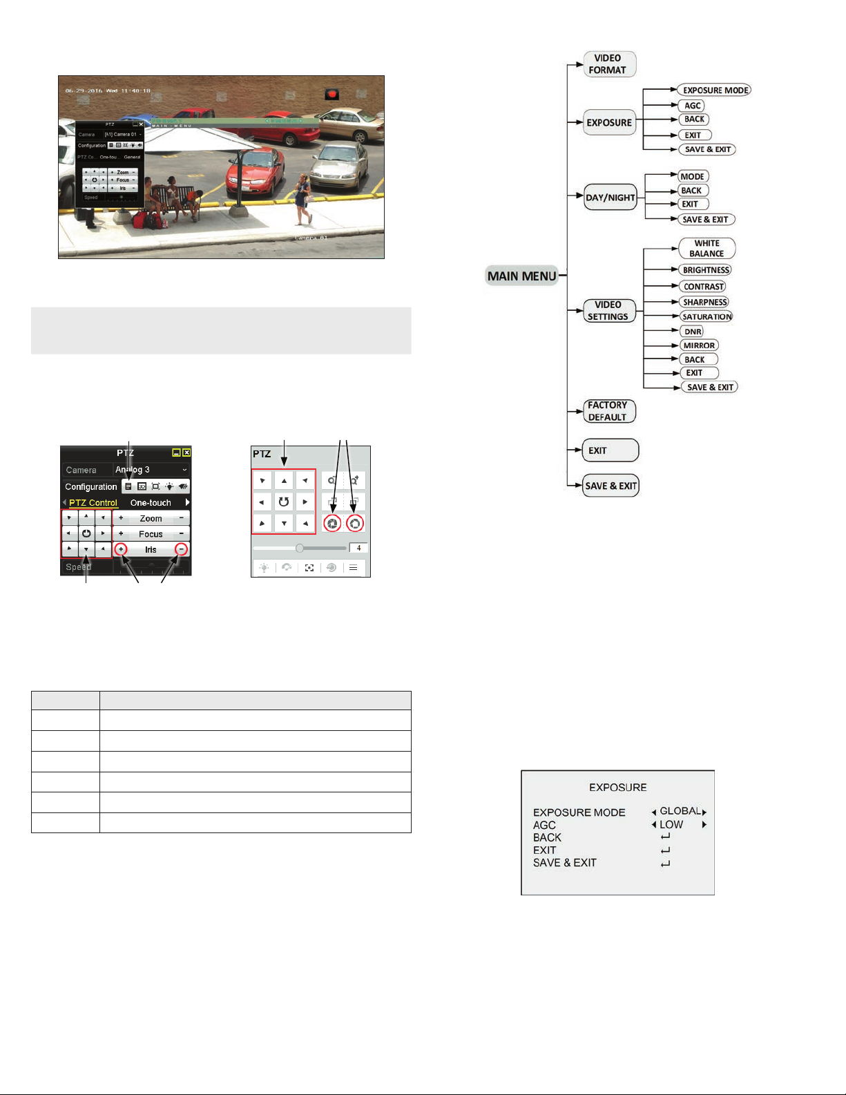
AGC (Automatic Gain Control): Optimizes the clarity of the image in poor light conditions. The AGC level can
be set to HIGH, MEDIUM or LOW.
Note: The noise will be amplied when setting the AGC level. The higher the level is, the more
obvious the noise is.
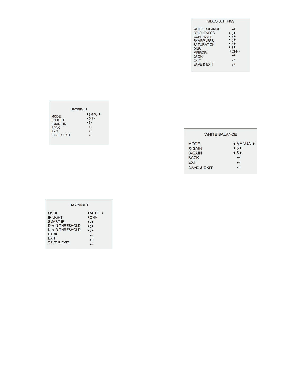
DAY/NIGHT
You can set the DAY/NIGHT mode to COLOR, BW (Black White) or AUTO.
• COLOR: The image is colored in day mode all the time.
• B & W (Black and White): The image is black and white all the time. IR LIGHT is on in the poor light
conditions. You can turn the IR LIGHT on and o and set the value of SMART IR in this menu.
B & W sub-menu
IR LIGHT: You can turn the IR LIGHT on or o to improve the image.
SMART IR: Use the Smart IR function to adjust the light to its most suitable level, and prevent the
image from over exposure. The SMART IR value can be adjusted from 0 to 3. The higher the value is,
the more obvious eects are.
• AUTO: Automatically switch Color, or B&W (Black and White) according to actual scene brightness.
You can turn on/o the IR LIGHT, and set the value of SMART IR in this menu.
AUTO sub-menu
IR LIGHT: You can turn on/o the IR LIGHT to meet the requirements of dierent circumstances.
SMART IR: Use Smart IR function to adjust the light to its most suitable intensity and prevent the over
exposure. The SMART IR value can be adjusted from 0 to 3. The higher the value is, the more obvious
eects are.
DN Threshold (Day to Night Threshold): Use the Day to Night Threshold to control the sensitivity of
switching the day mode to the night mode. You can set the value from 1 to 9. The larger the value is,
the more sensitive the camera is.
ND Threshold (Night to Day Threshold): Use the Night to Day Threshold to control the sensitivity of
switching the night mode to the day mode. You can set the value from 1 to 9. The larger the value is,
the more sensitive the camera is.
VIDEO SETTINGS
Move the cursor to VIDEO SETTINGS and click Iris+ to enter the submenu. In this menu you can set the
IMAGE MODE, WHITE BALANCE, BRIGHTNESS, CONTRAST, SHARPNESS, SATURATION, DNR, and MIRROR.
VIDEO SETTINGS menu
WHITE BALANCE: White balance used to adjust the color temperature according to the environment. It can
remove unrealistic color casts in the image. You can set WHITE BALANCE to AUTO or MANUAL.
AUTO: In AUTO mode, the white balance is being adjusted automatically according to the color
temperature of the scene.
MANUAL: You can set the R-GAIN/B-GAIN value from 1 to 255 to adjust the shades of red/blue color
of the image.
MANUAL MODE sub-menu
BRIGHTNESS: Brightness refers to the brightness of the image. You can set the BRIGHTNESS value from 1
(darkest) to 9 (brightest).
CONTRAST: This feature enhances the dierence in color and light between parts of an image. You can set
the CONTRAST value from 1 to 9.
SHARPNESS: Sharpness determines the amount of detail an imaging system can reproduce. You can set the
SHARPNESS value from 1 to 9.
SATURATION: Adjust this feature to change the color saturation. The value ranges from 1 to 9.
DNR (Digital Noise Reduction): Use DNR function to decrease the noise in the image, especially when
capturing moving images in poor light conditions, to produce a sharper image. You can set the DNR value
from 1 to 9.
MIRROR: This feature is used to reect the image. MIRROR can be set to OFF, H, V, and HV.
OFF: The mirror function is disabled.
H: The image ips 180° horizontally.
V: The image ips 180° vertically.
HV: The image ips 180° both horizontally and vertically.
FACTORY DEFAULT
Click Iris+ to enter the submenu, and click OK to reset all the settings to the factory default. Click Cancel
to return to the menu without resetting the camera.
EXIT
Move the cursor to EXIT and click Iris+ to exit the menu without saving.

5www.observint.com © 2019 Observint Technologies. All rights reserved.
SAVE & EXIT
Move the cursor to SAVE & EXIT, and click Iris+ to save the settings and exit the menu. If new settings are
not saved, they remain in eect only until the camera is powered o or reset.
Specications
Camera
Image Sensor 5 MP CMOS image sensor
Eective Pixels 2560 (H) × 1944 (V)
Min. Illumination Color: 0.01 Lux @ (F1.2, AGC ON), 0 Lux with IR
Shutter Time PAL: 1/25 s to 1/50, 000 s
NTSC: 1/30 s to 1/50, 000 s
Lens 2.4 mm xed Lens
Horizontal Field of View 110°
Lens Mount M12
Day & Night IR cut lter
Angle Adjustment Pan: 0° to 360°; tilt: 0° to 75°; rotate: 0° to 360°
Synchronization Internal synchronization
Frame Rate NTSC: 5 MP @ 20fps, 4 MP@30fps, 1080p @ 30 fps
PAL: 5 MP @ 20fps, 4 MP @ 25fps, 1080p @ 25 fps
Menu
AGC Support
D/N Mode Auto/Color/BW (Black and White)
White Balance ATW/MWB
BLC Support
DWDR (Digital Wide
Dynamic Range) Support
Language English
Functions Brightness, Sharpness, DNR, Mirror, Smart IR
Interface
Video Output 1 HD analog output
Switch Button Reserved.
General
Operating Conditions -40 °F to 140 °F (-40 °C to 60 °C), humidity: 90% or less (non-condensation)
Power Supply 12 Vdc ± 25 %
Power Consumption Max. 4.3 W
Protection Level IP67
Material Metal
IR Range Up to 65 ft (20 m)
Communication Up the coax (TVI output)
Dimensions 3.58” × 3.25” × 2.69” (91 mm × 82.6 mm × 68.3 mm)
Weight Approx. 0.77 lb (350 g)
Accessories
Compatible with:
ALI-AA1 outdoor pole mount adapter
ALI-AA2 outdoor corner mount adapter for ALI-AB1 and ALI-AB2
ALI-AB1
ALI-AB2
ALI-AB3 ceiling pendant mount bracket
ALI-AF4 ange adapter
ALI-AJ1 round junction box
ALI-AJ6 mini junction box
Cleaning
Clean the camera with an approved glass cleaning solution and a lint free cloth.
• Dust can be removed from the unit by wiping it with a soft damp cloth. To remove stains, gently rub
the surface with a soft cloth moistened with a mild detergent solution, then rinse and dry it with a
soft cloth. Do not use benzene, thinner or other chemical products on the camera assembly; these
may dissolve the paint and promote damage of the surfaces.
• Remove all foreign particles, such as plastic or rubber materials, attached to the camera enclosre.
These may cause damage to the surface over time.
Troubleshooting
Problem Possible Cause
Nothing appears on the screen - Check the power connection.
- Check the video signal cable connection to the monitor.
The video image is dim or not clear. - If the camera lens is dirty, clean it with a soft, clean cloth.
- Adjust the monitor controls, if necessary.
- If the camera is facing a very strong light, change the camera position.
- Adjust the lens focus.
The screen is dark. - Adjust the contrast control of the monitor.
- If you have an intermediate device, set the impedance (75 Ω /Hi-Z)
properly, and check the cable connections.
The camera is not working properly and
the surface of the camera is hot.
- Verify that the camera is correctly connected to an appropriate regulated
power source.
The image on the monitor ickers - Make sure that the camera isn’t facing direct sunlight or uorescent light.
If necessary,change the camera position.
Table of contents
Other ALIBI Security Camera manuals

ALIBI
ALIBI ALI-NS1024VR User manual

ALIBI
ALIBI ALI-CD1720 Series User manual

ALIBI
ALIBI ALI-TS1012R User manual

ALIBI
ALIBI ALI-TS2025R User manual

ALIBI
ALIBI ALI-BC1720P User manual

ALIBI
ALIBI ALI-NS2012VR User manual

ALIBI
ALIBI ALI-NT4002R User manual

ALIBI
ALIBI ALI-BC700G User manual

ALIBI
ALIBI ALI-NP3016RH User manual

ALIBI
ALIBI ALI-NS3034R User manual

ALIBI
ALIBI ALI-TS1022VR User manual

ALIBI
ALIBI ALI-CD1080PVF User manual

ALIBI
ALIBI ALI-NS2012R User manual

ALIBI
ALIBI ALI-NS4036R User manual

ALIBI
ALIBI ALI-TS4002R User manual

ALIBI
ALIBI ALI-TP7012RH User manual

ALIBI
ALIBI ALI-TP1013R User manual

ALIBI
ALIBI ALI-TP2013VR User manual

ALIBI
ALIBI ALI-TS3012R User manual

ALIBI
ALIBI ALI-TS3122R User manual