ALIBI ALI-NP3012RH User manual

1www.observint.com ALI-NP3012RH_CQ
161129
microSD card slot, reset button, CVBS video port inside.
Top (up)
Bottom (down)
Conduit port (2)
Mounting screw
hole (4)
Hook for safety
cable
Hole for camera
mounting screw (4)
Cable access
through mounting
surface
Camera base
locator pins
Junction box detail
What’s in the box
Your camera includes the following items:
• CD-ROM with manuals and ALIBI Power Tools
utilities
• Drill template
• Waterproof RJ-45 LAN coupling
• Junction Box
• Gang box adapter plate (not shown)
• Security wrench
• Mounting hardware Waterproof LAN coupling
Step 1. Install the camera
The camera includes hardware to install it directly to the Junction box provided, to a mounting surface
(without the junction box), or to a double-gang electrical box using the adapter plate provided. When
using the junction box, camera LAN and power drop cables can attach to extension cables inside the box.
The camera with or without the junction box can be installed on a ceiling (horizontal surface) or wall
(vertical surface). To install the camera, do one of the following:
To mount the camera using the Junction box
1. Remove the cover on the underside of the camera, and then install a microSD card. The card can
have a capacity up to 128 GB. Reinstall the cover.
2. Determine the best fasteners for securing the Junction box to mounting surface. The mounting
hardware provided is suitable for most surfaces.
3. Remove the junction box from the camera assembly by loosing the four captive screws.
4. Attach the drill template to the surface. Mark the location of the Junction box mounting screw
holes. If routing extension cables for the LAN, power, alarm devices, etc. through the mounting
surface, mark the location for that hole too. NOTE: When installing the box onto a wall, observe the
orientation for TOP and BOTTOM orientation markings inside the box and on the camera mounting
base, and orient the drill template properly.
ALI-NP3012RH 2.0 MP
Smart IP Bullet Camera
Quick Installation Guide
This document guides you through the basic steps to install and congure the ALI-NP3012RH camera. The
camera features:
• 2.0 MP high resolution sensor
• 4.7 - 94 mm motorized vari-focal lens
• HD real-time video up to 1920 x 1080 with tri-streaming and H.264 compression
• Smart detection including Intrusion, Line Crossing, Object left/removal, Face, Audio Surge, etc.
• Smart IR LED array with illumination up to 390 feet
• Supports distortion correction
• 3D-DNR noise reduction, 120dB Wide Dynamic Range (WDR)
• Dual power capable - Power over Ethernet (PoE) or 12 Vdc
• Internal heater for environments as cold as -40˚F
• Weatherproof - IP67 rated
• Internal microSD card storage up to 128GB (card not provided)
• 2-way Audio I/O, Alarm I/O
For more information about the software features of this camera, please refer to the ALIBI IP Camera V3
Software User Manual, available from your retailer.
Camera body
Lens
Articulated
mounting
bracket
Junction box assembly
(see detail below)
Sun Shield
Camera mounting base
Safety cable
Audio In/Out
connectors
LAN (RJ-45)
connector
12 Vdc,power
and ground
terminations
CVBS Out
Alarm In/Out
terminals

2www.observint.com
Mounting surface
Orientation mark
Mounting base screws (4)
Junction box mounting screws (4)
Drill template
Safety cable
Junction box
Camera
5. Drill holes in the mounting surface for the mounting screws and extension cables (if necessary).
6. Secure the Junction box to the mounting surface using appropriate fasteners.
7. Attach the camera safety cable to the safety hook inside the junction box.
8. Route the network LAN, audio, alarm and power extension cables between the junction box and the
devices they connect to. Do not apply power to the extension cables at this time.
9. Connect the extension cables to the camera drop cables.
10. Secure the camera to the junction box with four (4) screws.
11. Apply power to the camera.
To mount the camera onto a surface without the junction box
For this mounting option, the drop cables can be routed through the mounting surface, or through the
cable channel in the mounting base.
Mounting surface
Cable channel
Camera
Mounting base
screws (4)
1. Determine the best fasteners for securing the camera mounting base to mounting surface. The
mounting hardware provided may be suitable for some surfaces.
2. Remove the junction box from the camera assembly by removing the four mounting base captive
screws.
3. Using the camera mounting base as a template, mark the locations of the holes for the mounting
screws. Also mark the location of a hole for the camera drop cables if needed.
4. Route the network LAN, audio, alarm and power extension cables between the camera and the
devices they connect to.
5. Connect the extension cables to the camera drop cables.
6. Secure the camera to the mounting surface with four (4) screws.
7. Apply power to the camera.
To mount the camera onto an electrical box
1. Install a double-gang electrical box at the location where the camera will be installed.
2. Attach the gang box adapter plate provided to the electrical box using four (4) screws.
Double-gang box
Adapter plate
Orientation mark
Mounting base screws (4)
Adapter plate mounting screws (4)
Camera
3. Remove the junction box from the camera assembly by loosing the four mounting base captive
screws.
4. Attach the adapter plate to the double-gang box using at least two (2) screws.
5. Route the network LAN, audio, alarm and power extension cables between the devices they connect
to and out through the adapter plate. Do not apply power to the extension cables at this time.
6. Connect the extension cables to the camera drop cables.
7. Secure the camera to the adapter plate with four (4) screws.
8. Apply power to the camera.
Step 2. Install the Alibi Discovery Tool
Alibi Discovery Tool is a software utility used to “discover” Alibi cameras and NVRs/DVRs installed on the
physical Ethernet network (LAN) and change their network settings. Discovery Tool is provided on the CD
with your camera and is contained in Alibi Power Tools. To use Discovery Tool:
1. Insert the software CD provided with your camera into an optical drive on the Microsoft Windows
computer you will use to access your camera on the LAN.
2. On the CD, nd the folder that contains the Alibi Power Tools (Alibi Tools Utility).
3. Install Alibi Power Tools. Refer to the ALIBI™ Power Tools Installation and User Manual also provided
on the CD. When the program opens, the following screen appears.
4. Double click on the Discovery Tool icon. The tool will automatically discover Alibi cameras and
recorders installed on the network.
© 2016 Observint Technologies. All rights reserved.

3www.observint.com © 2016 Observint Technologies. All rights reserved.
In the example screen shown above, an ALI-NP1013VRH camera was discovered. Notice that the IP
address of the camera is 192.168.1.64 (default IP address). This camera, although congured for a
subnet that is probably foreign to the network it is installed on, is still found by the tool.
5. To change the network settings of the camera to be compatible with the subnet where it is installed,
do the following:
a. Click on the device to highlight it. Notice that the network parameters for the device populate
the elds in the right frame.
b. Modify the network settings to values compatible with the subnet where it is installed:
»If the IPv4 Address shown for the camera is 192.168.1.64 (default IP address) and the
camera is new (un-congured) or was reset to its factory default state, the camera did not
nd a DHCP server on the network. Modify the parameters in the right pane to values you
prefer and are compatible with the network. An example is shown in the screen below.
»If the IPv4 Address shown for the camera is something other than 192.168.1.64 (default
IP address) and the camera is new or was reset to its factory default conguration, the
camera did nd a DHCP server on the network and acquired new network parameters that
are compatible with the network. If necessary, change the parameters in the right pane to
values that you prefer and are compatible with the network. An example is shown in the
screen above.
c. Enter the admin password for the camera in the Password eld. The default admin user
password for Alibi cameras is 1111.
d. Click the Modify button. The new IP address, port, and other settings will change and
appear in the list with the device you modied.
6. Close the Alibi Tools Utility by clicking the Close icon ( T) in the upper-right corner of the screen.
Step 3. Remote login
To access the camera from a computer on the LAN:
1. Log into the operating system as a user with administrative privileges.
2. Open the Microsoft Internet Explorer browser on your compute and enter the IP address of the
camera in the URL eld. In the example below, the IP address of the camera is 192.168.1.64.

4www.observint.com © 2016 Observint Technologies. All rights reserved.
3. In the login window, enter a User Name and Password with Administrator privileges in the
appropriate elds, then click Login. The default User Name and Password for Alibi cameras is
admin and 1111.
4. If the password you enter for your camera is a weak password, the following pop-up window will
appear. Follow the instructions to create a “strong” admin password.
NOTE
Observint recommends using strong passwords in all of your surveillance devices. Strong passwords
have a minimum of 8 characters with upper case and lower letters, numbers and special characters.
And we recommend you reset your password regularly, especially in high security systems. Resetting
the password monthly or weekly will better protect your security system from hackers and criminals.
5. If this login is the rst login to an Alibi camera from your computer and browser, continue with the
following sub-steps to install a plugin:
a. After a successful login to the camera, a message will appear in the middle of the Live View
window requiring you to load a plug-in. Click on the message to continue.
b. When the following screen appears, click Run to download the plug-in (WebComponents)
and continue.
c. When the following screen appears, click Run to install WebComponents.
d. Allow the plug-in installation to complete. When the following window appears, click
Finish.
6. Log into the camera again to see the Live View - Main stream window.

5www.observint.com © 2016 Observint Technologies. All rights reserved..
Capture Record Zoom
Live View image
NOTE: You can also observe video from the camera by plugging the Video Test Monitor cable into the CVBS
monitor connector in the camera, then attaching it to a spot monitor.
Step 4. Adjust the camera for your surveillance target
1. While observing live video from your camera, loosen the Pan, Tilt and Rotation lock screws at least
two turns using the security L-wrench provided, then move the camera to point at the center of your
surveillance target. Tighten the lock screws to hold the camera in position.
Pan lock screw - Pan: 0˚ ~ 360˚
Tilt lock screw
Tilt: 0˚ ~ 100˚ Rotation lock screw
Rotation: 0˚ ~ 360˚
2. Reinstall the black liner (if removed).
3. Click the Zoom icon at the bottom of the Live View window (see above) to adjust the camera zoom.
4. Reinstall the dome assembly.
Step 5. Adjust the video display
The video Display Settings menu includes the image-related congurable parameters for the camera. It
contains several sub-menus such as Image Adjustment, Exposure Settings, Day/Night Switch, etc. that can
be opened or closed for compactness. Additionally, several adjustments can be seen in the Live View image
on the menu. To open the Display Settings menu, go to Setup tab | Image | Display Settings
Congurable parameters include parameters for Day - Night Scheduled-Switch and Auto-Switch. For
Scheduled-Switch, congure the following:
• Start Time and End Time: set the time when settings change.
• Select either Common settings, Day settings and Night settings. Each submenu has options
relative to the title.
• Switch Day and Night: Select either Auto-Switch or Scheduled-Switch.
—If using Auto-Switch, open the Day/Night Switch submenu to select the Sensitivity,
Filtering Time, and Smart IR feature ON or OFF.
—If using Scheduled Switch, set the Start Time and End Time of the switch, then open
the Day/Night Switch submenu to select the Smart IR feature ON or OFF.
Also, click the Common, Day and Night tabs to set the Saturation, Hue, Brightness,
Contrast and Sharpness for Day and for Night modes.
Refer to the ALILBI IP Camera V3 Software User Manual for additional settings.
For Auto-Switch, set the following
• Image Adjustment submenu: Open the Image adjustment submenu to set the Saturation, Hue,
Brightness, Contrast and Sharpness of the video image. Each parameter can be set to a level of 0
~ 100 either by moving the slider or entering the value in the box on the right. The eect of the
adjustment will appear in the Live View image in the menu.
• Exposure Settings submenu: In this submenu, set the following for the best performance:
—Iris Mode: Select Auto or Manual. Some cameras may not oer both options.

6www.observint.com © 2016 Observint Technologies. All rights reserved.
—Exposure Time: Value ranges from 1/3 to 1/100,000 s. The nominal value is 1/150. Adjust it
according to the lightening condition.
—Gain: Set the gain to show the optimal brightness level.
• Focus submenu: Select either Auto, Manual, or Semi-auto for the best performance during
changing lighting conditions.
• Day/Night Switch submenu: You can set the Day/Night switch to Day, Night, Auto, or Schedule.
The option you select determines the submenu options.
—Day or Night: These options both have one parameter: Smart IR.
—Auto: If you select Auto switch, you can set the sensitivity (0 .. 7), ltering time and Smart IR.
—Schedule: Use Schedule to set that Start Time and End Time for the switch. Smart IR is
also selectable.
• Backlight Settings: Backlight settings include BLC Area (O, Up, Down Left Right Center), the
area to control, and WDR (Wide Dynamic Range) ON or OFF.
• White Balance: White Balance selection is used to correct colors in the image depending on the
lighting source. You can also set the white balance manually (MWB), using Automatic White Balance
(AWB1), and lock the white balance setting (Locked WB).
• Image Enhancement: Options in this submenu include Digital Noise Reduction (DNR) ON or OFF.
If ON, you can also adjust the level of noise reduction.
• Video Adjustment: Video Adjustment includes:
—Mirror: Mirror adjustment enables you to ip the image (Up/Down), ip Left/Right (reect
or Center).
—Rotate: Rotate rotates the image +90 degrees. Reverses the aspect ratio. Useful for viewing
long hallways from a ceiling mount installation.
—Video Standard: Select 60 Hz for NTSC format.
—Capture Mode: To make a complete use of the 16:9 aspect ratio, you can enable the capture
mode when you use the camera in a narrow view scene
Refer to the ALILBI IP Camera V3 Software User Manual for additional settings.
Step 6. Change default password
Observint Technologies strongly recommends that you change the default admin user password in your
camera from “1111” to a dierent code to help protect against unauthorized access. You must login to the
camera with the admin user name to change the admin password. To change the admin password:
1. Click the Setup tab, and then click System in the left frame.
2. Click the User Management tab in the menu on the right.
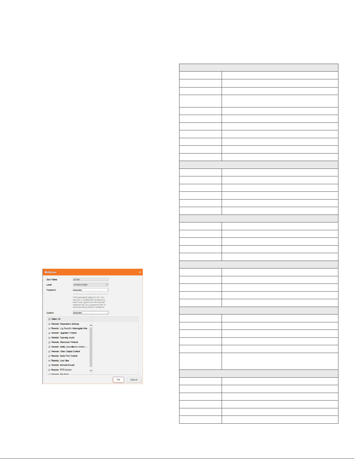
3. Click the admin User Name to select (highlight) it, and then click the Modify button. The Modify
User pop-up window will open.
4. In both the Password and Conrm elds, enter a new password. The password can contain 0 .. 9,
A .. Z, and a .. z. Record your new password for future reference.
5. Click the OK button at the bottom of the window.
Camera Reset
To Reset the camera to its factory default conguration, press and hold the Reset button, located beneath
the cover on the underside of the camera, for 10 seconds during power on or reboot.
Specications
Camera
Image Sensor 1/2.8” Progressive Scan CMOS
Resolution Up to 1920 x 1080
Eective Pixels Approx. 2.0 Megapixel
Minimum Illumination 0.005 Lux, @ (F1.2 AGC ON), 0 Lux with IR
0.007 Lux, @ (F1.4 AGC ON), 0 Lux with IR
Day/Night IR Cut Filter with auto switch
Electronic Shutter (sec) 1/3 s ~ 1/100,000 s
Slow shutter Support
Auto-iris DC drive
Wide Dynamic Range 120 dB
Noise Reduction 3D DNR
IR Illuminators Smart IR Array, 850 nm
Lens
Lens 4.7 ~ 94 mm @ F1.4 angle of view: 53.8° ~ 3.1°
Lens Mount AF automatic focusing and motorized zoom lens
Focal Length 4.7 ~ 94 mm
Auto Iris DC drive
Focus Auto/Semiautomatic/Manual
Horizontal Viewing Angle 91.2° (Wide) ~ 28.3° (Tele)
Video
Video Compression Format H.264+ / H.264 / MJPEG / MPEG4
H.264 type Baseline Prole / Main Prole / High Prole
Frame Rate 60 Hz: 60 fps (1920 × 1080) / (1280 × 960) / (1280 × 720)
Third Stream Independent with Main Stream and Sub Stream, up to 60 Hz: 1 fps (1920 × 1080)
Video Bit Rate 32 kbps ~ 16 Mbps
Audio
Environment Noise Filtering Support
Audio I/O Support dual audio track, stereo
Audio Sampling Rate 16kHz / 32kHz / 44.1kHz / 48kHz
Audio Compression G.711 / G.722.1 / G.726 / MP2L2
Audio Bit Rate 64 Kbps (G.711) / 16 Kbps (G.722.1) / 16 Kbps (G.726) / 32-128 Kbps (MP2L2)
Features
Motion Detection Yes
Event Notication Alarm Output, Email, FTP
Privacy Mask Yes
ROI Encoding Up to 24 areas with adjustable levels
Defog Yes
Video Analytics
Line Crossing Detection, Intrusion detection, Region entrance, Region exiting, Unattended
baggage, Object removal, Scene change detection, Sudden audio increase/decrease detec-
tion, Defocus detection, Face Detection, Object Counting
Interface
Audio 1-ch 3.5 mm audio in (Mic in / Line in)/out interface
Communication Interface 1 RJ45 10M / 100M / 1000M Ethernet port, 1 RS-485 interface
Alarm 1 input, 1 output (up to 24 Vdc 1A or 110 Vac 500 mA)
Video Output 1 Vp-p composite output (75 Ω/BNC)
On-board storage Built-in Micro SD / SDHC / SDXC slot, up to 128 GB
Reset Button Yes

7www.observint.com © 2016 Observint Technologies. All rights reserved.
Network
Network Storage NAS (Support NFS,SMB/CIFS), ANR
Alarm Trigger Motion detection, Tampering alarm, Network disconnect, IP address conict, Storage
exception
Protocols TCP/IP, ICMP, HTTP, HTTPS, FTP, DHCP, DNS, DDNS, RTP, RTSP, RTCP, PPPoE, NTP, UPnP, SMTP,
SNMP, IGMP, 802.1X, QoS, IPv6, Bonjour
Security User Authentication, Watermark, IP address ltering, Anonymous access
Standard ONVIF (PROFILE S,PROFILE G), PSIA, CGI, ISAPI
Smart features
Behavior Analysis Line crossing detection, Intrusion detection, Region entrance, Region exiting, Unattended
baggage, Object removal
Line Crossing Detection Cross a pre-dened virtual line
Intrusion Detection Enter and loiter in a pre-dened virtual region
Region Entrance Enter a pre-dened virtual region from the outside place
Region Exiting Exit from a pre-dened virtual region
Unattended Baggage Objects left over in the pre-dened region such as the baggage, purse, dangerous materials
Object Removal Objects removed from the pre-dened region, such as the exhibits on display.
Exception Detections Scene change detection, Sudden audio increase/decrease detection, Audio loss detection,
Defocus detection
Recognition Face detection recognition
Statistics Object Counting (Entrance and Exit object number is accounted and showed on screen in
real time)
General
Power Requirements 12 Vdc ± 10%, PoE (802.3at)
Power Consumption DC: 10.8 W, PoE: 14 W
IR Array Range 390 ft (120 m)
Weight 4.41 lbs
Dimensions 4.09" H x 3.94"W x 12.28" D
Operating Temperature -22°F ~ 140°F (heater o), -40°F ~ 140°F (heater on)
Operating Humidity 0% ~ 95% RH, Non-condensing
Ingress Protection IP67
Color White/Black
Material Aluminum (body), Polycarbonate (lens cover)
Approvals CE, FCC, RoHS
System Requirements
Operating System Microsoft®Windows® XP / Vista / 7 / 8 / 10, Apple® OSX
Processor Intel® Pentium® 4 3.0 GHz or later
Memory 1GB or above RAM
Display 1024 x 768 resolution or higher
Web Browser Internet Explorer® 6.0 or above, Apple® Safari® 5.02 or above, Mozilla® Firefox® 3.5 or above
Supplied Accessories
CD ROM (User’s Guide, Installation Tools)
Quick Installation Guide
Mounting Hardware and Template
Junction box
Gang box adapter plate
Table of contents
Other ALIBI Security Camera manuals

ALIBI
ALIBI ALI-CD700 User manual

ALIBI
ALIBI ALI-NS8014VR User manual

ALIBI
ALIBI ALI-TS2025R User manual

ALIBI
ALIBI ALI-NS4112R User manual

ALIBI
ALIBI ALI-NS1025VR User manual

ALIBI
ALIBI ALI-NP7022RT User manual

ALIBI
ALIBI ALI-BC1720PVF HD-TVI User manual

ALIBI
ALIBI ALI-BC700G User manual

ALIBI
ALIBI ALI-NS4012R User manual

ALIBI
ALIBI ALI-PTZ23X User manual

ALIBI
ALIBI ALI-CD700WAIR User manual

ALIBI
ALIBI ALI-TS4115R User manual

ALIBI
ALIBI ALI-NS2004R User manual

ALIBI
ALIBI ALI-TS4015R User manual

ALIBI
ALIBI ALI-TS3012R User manual

ALIBI
ALIBI ALI-NS7004R User manual

ALIBI
ALIBI ALI-TS1012R User manual

ALIBI
ALIBI ALI-TS2018VR User manual

ALIBI
ALIBI ALI-IPV30 User manual

ALIBI
ALIBI ALI-NS1034R User manual