ALIBI ALI-NS4114R User manual

1www.observint.com
ALI-NS4114R 4MP Vari-focal IP Bullet Camera Quick Installation Guide
ALI-NS4114R_CQ
180410
Safety cable
Conduit
adapter
Sealing plug
for interface
wiring (5)
Captive screws
connect to
adapter plate (3)
Side inlet
cover
Junction box (inside view)
Hook for safety cable
Interface terminals
for alarms, audio,
LAN, power
Adjustment
bracket lock
screw
Back of camera (junction box removed)
What’s in the box
Your camera includes the items shown below.
Mounting hardware
Insertion tool
Junction box screws
Security L-wrench
Conduit adapter BNC video
maintenance
cable
Step 1. Route wiring to the camera
Interface cables can be routed into the camera either through the adapter plate (through the mounting
surface or through a gang box), through the side inlet of the junction box, or through conduit.
NOTE
When selecting a mounting location for the camera
• Make sure that there are no reective surfaces near to the camera lens. IR light from the camera may
bounce back onto the lens causing reections.
• Determine how wiring is routed into the camera. The cable can be routed through conduit
(a threaded conduit adapter is provided), through the mounting surface and access hole in the
mounting plate, or through the side inlet.
See photos above. The camera includes connectors for the following:
• Ethernet (required): The Ethernet drop cable can connect to a LAN extension cable from a
switch or Network Video Recorder. The camera can be powered across the LAN using power over
Ethernet (PoE) injection. See the Specications section at the end of this document for power
requirements.
• 12 Vdc power input (optional if PoE powered, required if not): If powering the camera
with a long power extension cable, refer to the tables at the end of this guide for wire gauge
requirements. Voltage input at the camera can be within the range 12 Vdc ± 25%.
This document guides you through the basic steps to install and congure the ALI-NS4114R network
vari-focal bullet camera. This camera features:
• 1/2.5” 2560 × 1440 pixel Progressive Scan CMOS sensor
• 2.8 ~ 12 mm motorized vari-focal lens
• Low light 0.008 lux color minimum illumination
• H.265, H.265+, H.264+, H.264 video compression
• 120 dB Wide Dynamic Range
• Back light compensation (BLC) / 3D dynamic noise reduction (DNR)
• IP67 weatherproof, IK10 vandalproof rated
• 4 behavior analyses and face detection
For more information, refer to these documents - available from your equipment vendor:
• ALIBI™ Tools Utility Installation and User Manual
• ALIBI™ Witness 2.0 r3 App for Android or iOS Quick Start Guide
• ALIBI™ IP Camera Firmware Version 5.4 User Manual (or later) provided at:
AlibiSecurity.com/resources
Lens
Sun shield
Camera body
Maintenance panel
Adjustment
bracket
Junction box
Junction box screw (4)
Adapter plate
Screw stud for
junction box (3)
Hole for surface
or gang box
cable routing
Holes (2) for
single-gang box
mounting (#2)
Holes (4) for
surface mounting
or double-gang
box (#1)
Adapter plate
Side inlet
cover
Side inlet with
conduit adapter
Sealing plug
for interface wiring (5)
Sealing plug
for LAN/PoE cable
Ground terminal
Junction box (adapter plate side)

2www.observint.com
• Alarm IN/OUT, Audio IN/OUT (optional): Connect these leads to auxiliary devices as needed.
The camera supports one alarm input, one alarm output, one audio input and one audio output.
Audio IN and OUT terminations require 3.5 mm standard audio plugs.
• Ground: A ground terminal is provided on the junction box for attaching an earth ground to the
camera. Follow local electrical codes for grounding procedures.
1. Route a LAN extension cable from a network switch or Network Video Recorder to where the
camera will be installed.
2. If the camera is not powered using PoE, route 12 Vdc power cables from an adequate power
source to the location where the camera will be installed. Refer to the Specications section for
power requirements. Also, for long line power leads, refer to the Wire Gauge Standards and 12
Vdc Wire Gauge and Transmission Distance tables at the end of this document. Voltage input at
the camera can be within the range 12 Vdc ± 25%.
CAUTION
Do not apply power to the camera at this time. Before applying power to the camera, ensure
that the polarity is correct. An incorrect connection may cause a malfunction and can damage
the camera.
3. Install alarm input and out devices as needed, and then route wires from them to where the
camera will be installed. Alarm terminations for one input (NO or NC) and one output alarm
device (DC or AC) are screw-down connectors that accommodate bare wires.
4. Install audio input and out devices as needed, and then route cables from them to where the
camera will be installed. Audio terminations in the camera are 3.5 mm plugs.
Step 2. Install the camera
Install microSD card
Install a microSD card in the camera to locally save alarm and status information, and locally record
video and video captures. Refer to the Specications section for storage card requirements. To install the
card:
1. Un-package the camera and lay it upside down on a clean, soft surface.
2. Use the security L-wrench provided to remove the small maintenance panel cover on the
underside of the camera body. The cover conceals the microSD card slot, Reset button and
connector for the video maintenance BNC cable.
microSD
card slot
Maintenance panel
NOTE
RESET: To restore the camera to its default settings, hold down the RESET button for about 10s when
the camera is powering on or rebooting. Reset will deactivate the camera and restore the default IP
address, port number, conguration settings, etc.
3. Insert the microSD card into the slot shown. The card should slide in smoothly. Push the card in
until it clicks into place.
4. Reinstall the maintenance panel cover. Ensure that the seal is positioned correctly before
tightening the cover screws.
Remove junction box and adapter plate
1. With the camera laying on a clean, soft surface, use the L-wrench to remove the four junction
box screws from the camera, and then carefully lift the junction box with the adapter plate away
from the camera.
Junction box screw (4)
Adapter plate screw (3)
2. Use the L-wrench to loosen the three captive adapter plate screws, and then separate the adapter
plate from the junction box. See above.
Install the adapter plate
The camera can be mounted onto a wall or ceiling, or onto a single-gang or double-gang electrical box.
If mounting the camera onto a wall or ceiling, screws and wall inserts, appropriate for many surfaces,
are provided, but more appropriate fasteners may be required.
The mounting surface should
support at least four (4) times the weight of the camera.
1. To attach the adapter plate to a mounting surface:
a. Use the adapter plate as a template to mark the location of the holes for the mounting
screws. Use the four holes marked “1” for the mounting screws. If mounting the camera to
a wall, the “FRONT” mark on the adapter plate should point up. If mounting the camera to
a ceiling, the “FRONT” mark should point toward the front (lens) of the camera.
“FRONT” mark
b. Drill holes into the surface to accommodate the fasteners for anchoring the camera. If the
interface cables will be routed through the surface, also drill a hole for the cables through
the surface matching the large hole in the adapter plate.
c. Secure the adapter plate to the surface with four screws. Route the LAN and other
interface cables to the mounting location:
i. Route the cables through the mounting surface and adapter plate at this time, if
preferred.
ii. If routing the interface cables through conduit, attached the threaded conduit
adapter to the conduit, and then route the cables through the conduit.
To attach the adapter plate to a gang box:
a. Anchor the gang box to the mounting surface securely. The gang box must be able to
support at least four times the weight of the camera.
b. Remove the cover screws from the gang box. These screws will used to secure the adapter
plate to the box.
c. If the gang box is on a wall, orient the adapter plate on the gang box so that the “FRONT”
mark on the plate is pointing up. If the gang box is on a ceiling, orient the “FRONT” mark
on the plate so it points toward the front (lens) of the camera.
d. Attach the adapter plate to the gang box. For single-gang boxes, use the screws in the
holes marked “2”. For double gang boxes, use the screws in holes marked “1”.
e. Route the LAN and other interface cables through the gang box, and then through the
hole in the adapter plate.
f. For outdoor installations, seal holes drilled through exterior surfaces to block moisture and
other contaminants.
Install the junction box
To install the junction box, rst insert the interface cables through the sealing plugs in the junction box,
and then attach the junction box to the adapter plate.
1. Attach the ground cable to the ground terminal in the junction box.
2. Remove the largest sealing plug from the junction box. This plug will be used for the LAN cable.
3. To install the sealing plug on the LAN cable:
a. Clip the insertion tool provided onto the RG-45 connector of the LAN cable. See abelow.
b. Force the insertion tool with the LAN cable through the sealing plug. Observe the
orientation of the sealing plug in the drawing below. See b below.
© 2018 Observint Technologies. All rights reserved.

3www.observint.com © 2018 Observint Technologies. All rights reserved.
Insertion tool Sealing plug
a. c.b. d.
c. Slide the sealing plug down past the RJ-45 connector. See c above.
d. Remove the insertion tool from the LAN cable. See d above.
e. Reinstall the sealing plug with the LAN cable into the junction box.
4. Similar to the procedure in the previous step, use the insertion tool to install the other power,
audio and alarm cables through the sealing plugs in the junction box. See below.
Side inlet cover
5. Reattach the junction box to the adapter plate. If you are using conduit with the conduit adapter
to route the interface cables, remove the side inlet cover from the junction box, and the slide the
conduit adapter into the side inlet before reattaching the junction box.
Install the camera
1. Hook the safety cable on the junction box onto the tang in the camera module and allow the
camera to hang freely.
Junction box
Safety cable
Safety cable tang on
camera module
Interface cable
connectors
2. Attach the interface cables to the connectors on the camera module. See photo below for
connector identication.
3. Attach the interface cables to the connectors on the camera module. See above.
4. Reattach the camera module to the junction box using the four screws removed earlier. \
5. Apply power to the camera through the 12 Vdc power cable or PoE injector, as congured.
Step 3. Install the Alibi Config Tool software
NOTE: If the camera LAN extension cable is attached to a Network Video Recorder (NVR), skip this step.
The Alibi Cong Tool is a PC-based network utility for discovery of Alibi compatible devices. It provides
an easy way to activate devices, congure camera and recorder network conguration settings, and set
device passwords. It can be installed on a Microsoft® Windows® operating system that has direct access
to the network where your Alibi devices are installed. You can download the Alibi Conguration Tool
from Supercircuits.com or AlibiSecurity.com/Resources.
1. Download the Alibi Cong Tool from the Supercircuits.com or AlibiSecurity.com/Resources
website. At the time when this document was published, the le is named: alibi-cong-tool.
zip and is about 80MB.
2. Un-zip the le on a computer with Microsoft Windows (Windows 7 or newer) that is connected
to the LAN where your Alibi camera is connected.
3. Run the le contained in the zip le: Alibi Cong Tool.exe. Follow the on-screen instructions
to install the le.
4. Open the Alibi Cong Tool application. When the application opens, it automatically “discovers”
and lists all Alibi compatible devices on the LAN. See below.
Notice: In the screen above, the tool discovered devices with IP addresses of 192.168.0.xxx and
192.168.3.xxx. It will also list other Alibi compatible devices on the LAN, and devices with the
address 192.168.1.64 (an inactive Alibi device).
Step 4. Activate Inactive Alibi device
NOTE: If the camera LAN extension cable is attached to a Network Video Recorder (NVR), skip this step.
Refer to the documentation available for your NVR rmware for the procedure to activate the camera, if
necessary.
When an Alibi device is rst installed, or reset to its factory conguration, it must be “Activated” before
it can be used. In the Alibi Conguration Tool, “Inactive” devices have a Security status of Inactive,
and an IPv4 address of 192.168.1.64. A device is “Activated” when a password is assigned to the
admin username of the device.
In the example below, an ALI-NS4114R camera is activated and congured for its network. The
procedure is similar for all other Alibi network cameras currently available.
1. Scan through the list of devices the Alibi Cong Tool discovered for the Inactive device you want
to activate (see below). Click on the device in the list to highlight it, and then click the select box
to check it. See below.

4www.observint.com © 2018 Observint Technologies. All rights reserved.
Activate
2. Click the Activate button. In the Activate window, you will create a password for the admin
(administrator) username.
a. In the Activate window, enter an a password for admin in the New Password eld.
Include a combination of uppercase, lowercase alphabetic characters and numbers to
create a “Strong” password. The rating is shown beneath the eld. See above.
b. Enter the admin password again in the Conrm eld, and then click Activate. In the
screen below, notice that the device Security status shows “Active”. Record your admin
password for reference later.
CAUTION
If you lose your admin (administrator) password, you cannot congure the device or restore
it to its factory settings. To reset your password, call your support organization for specic
instructions.
Notice that although the device is now activated, it retained the default IP address.
Step 5. Modify Network Parameters
NOTE: If the camera LAN extension cable is attached to a Network Video Recorder (NVR), skip this
step. The camera will receive network conguration settings from the NVR. Refer to the documentation
available for your NVR rmware for more information.
You can change the network parameters of devices that are active.
1. In the list of devices discovered, click on the device you want to change the network settings for,
and then click the select box to check it. See below.
Modify Network Parameters
2. In the popup window, edit the current network parameters, and then enter the admin user
password in the eld at the bottom.
a. Enable DHCP: You can select Enable DHCP to acquire compatible network settings
from a DHCP server installed on the LAN. However, these settings can be changed by the
DHCP server. Since it is recommended to use an unchanging IP address, you can use DHCP
to acquire compatible network settings, and then uncheck Enable DHCP and save that
conguration to retain the new network parameters.
b. In the example below, the IPv4 address was changed to 192.168.3.100, and the IPv4
Gateway was changed to 192.168.3.1. The Subnet Mask here did not need to be changed.
These settings were determined to be compatible with the network router and other
devices that share the same router.
3. Click OK to save your settings. The parameter change(s) will be shown device’s network
parameters (see below).
Step 6. Login to the camera
NOTE: If the camera LAN extension cable is attached to a Network Video Recorder (NVR), skip this step.
Microsoft® IE is used to access your camera remotely. IE must run as an Administrator to use all features
available through a remote login to the camera.
Setting MS Internet Explorer to run as an Administrator
Window 7: To run IE as an Administrator:
1. Find or create an IE icon on your computer desktop.
2. Hold down the shift key, and then right-click on the IE icon.
MS Internet
Explorer icon
Run as administrator
3. Click Run as administrator in the pop-up menu.
Window 10:
To run IE as an Administrator:
1. Find MS IE in the start menu. Usually this is found in the Windows Accessories group.
2. Pin the entry to Start.
3. Right click on the Internet Explorer tile, and then select More | Run as administrator.

5www.observint.com © 2018 Observint Technologies. All rights reserved.
Run as
administrator
To login to the camera from a computer on the same LAN:
1. Open your Microsoft Internet Explorer (IE) browser on your computer and enter the IP address of
the camera in the URL eld. In the example below, the IP address of the camera is 192.168.3.100.
2. In the login window, enter admin for the User Name and the password you created in the
Password eld, the click Login.
3. If this is the rst time you are logging into a camera, you may see the message in the following
screen. If this appears, follow the sub-steps below.
a. Click on the message to install the plugin.
b. In the message bar at the bottom of the screen, click Run. Follow the on-screen
instructions to install WebComponents. When the following screen opens, click Finish.
The Live View screen with the camera video image should appear.
Capture, Record, Zoom icons
Screen select tabs Logout buttonLive View image
Step 7. Adjust camera pan, tilt and rotation
Adjust the camera pan, tilt and rotation to point the camera at your surveillance target. When pointing
the camera, use the Live View display on a recorder or remote login. You can also attach the BNC video
maintenance cable to the connector on the maintenance panel, and then attach it to CVBS monitor to
see a live view video from the camera.
1. While observing live video from the camera, use the L-wrench to loosen the adjustment bracket
lock screw on the back of the adjustment bracket until the camera is free to move and rotate. The
location of the lock screw is shown in the photos on page 1 of this guide.
2. Point the camera at your surveillance target, changing the pan, tilt and rotation as needed. Be
certain to stay within the specied pan, tilt and rotation ranges of the camera. See below.
Pan range: 0˚ ~ 360˚
Tilt range: 0˚ ~ 90˚
Rotation range: 0˚ ~ 360˚
3. Tighten the adjustment bracket lock screw to securely hold the camera in place.
Step 8. Verify PTZ functionality
Use the PTZ control panel to exercise the zoom and focus functionality of the camera. Accessing to the
control panel depends on whether the camera is installed as a device on a LAN or if it is connected to a
NVR. Select the installation type below for your camera to complete this step.
For cameras installed on a LAN
1. Log into the camera and then open the Live View window.

6www.observint.com © 2018 Observint Technologies. All rights reserved.
Open / Close PTZ Control Panel PTZ Control Panel
2. Click the joystick icon to open the PTZ control panel. See above.
3. In the PTZ control panel, click each zoom and focus button shown in the graphic below. Verify
that the camera performs as expected. Refer to the Specications section of this document for
zoom range.
Direction buttons Zoom In / Out
Focus In / Out
Iris Open / Close
Continuous
pan
For cameras connected directly to an NVR
Refer to the rmware manual for your NVR for specic instructions to perform the following:
1. Log into the NVR at the NVR console.
2. In the Live View display, nd the PTZ camera you installed. Click on the camera to open the
Quick Setting toolbar.
PTZ Control icon
3. Click the PTZ Control icon. See above.
4. In the pop-up PTZ menu, click the PTZ Control tab. See below.
Zoom In / Out
Focus In / Out
Iris Open / Close
5. In the PTZ Control panel, click the zoom and focus buttons labeled in the graphic above. Verify
that the camera performs as expected. Refer to the Specications section of this document for
motion and zoom ranges.
Step 9. Adjust the camera image for your surveillance target
Use the rmware menus to adjust the brightness, contrast, saturation and sharpness of the video image
if necessary. These settings are initially optimized at the factory and may not need adjustment. When
adjustments are necessary, the paths to the image settings menus are dierent if the camera is installed
as a device on a LAN, or if it is connected to a NVR. Select the installation type below for your camera to
complete this step.
For cameras installed on a LAN
1. If necessary, log into the camera on the LAN with administrative credentials.
2. After adjusting the camera for the a typical eld of view, click the Setup tab, and then click the
Image link in the left frame.
3. Adjust the Brightness Contrast, Saturation and Sharpness of the image. Each parameter can be
set to a level of 0 ~ 100 either by moving the slider or entering the value in the box on the right.
The eect of the adjustment will appear in the Live View image in the menu.
Refer to the rmware user manual for your camera to use the other submenus on this screen.
For cameras connected directly to an NVR
1. Log into the NVR with administrative privileges.
2. Open the rmware Image menu. Go to Menu | Camera Management | Image
3. In the Camera eld drop down list, select the camera you want to congure. In the example
above, [D1]IPCamera 01 is selected.
4. Drag the Brightness, Contrast, Saturation and Hue adjustment markers left or right to
perfect the image from the camera. For some adjustments, you can click the up ( 5)or down
( 6)icons near the adjustment value (on the right side) to incrementally change the value of
those adjustment.
5. Click Apply to save your settings for this camera.
Refer to the rmware user manual for your NVR to use the other submenus on this screen.
Specications
Camera ALI-NS4114R
Image Sensor 1/2.5” Progressive Scan CMOS
Signal System PAL / NTSC
Min. Illumination Color: 0.008 lux @ (F1.2, AGC ON), 0.016 lux @ (F1.6, AGC ON),
0 lux with IR
Shutter time 1/3 second to 1/100,000 second
Slow shutter Supported

7www.observint.com © 2018 Observint Technologies. All rights reserved.
Lens, FOV
2.8 ~ 12 mm
Horizontal eld of view: 114° to 32°
Vertical eld of view: 59° to 18°
Diagonal eld of view: 141° to 36.5°
Lens Mount φ14
Adjustment Range Pan: 0° ~ 360°, tilt: 0° ~ 90°, rotate: 0° ~ 360°
Day& Night IR cut lter with auto switch
Wide Dynamic Range 120 dB
Digital noise reduction 3D DNR
Focus Motorized VF lens
Compression Standard
Video Compression
Main stream: H.265 / H.264
Sub-stream: H.265 / H.264 / MJPEG
Third stream: H.265 / H.264
H.264 Type Main Prole / High Prole
H.264+ Yes
H.264+ Main Prole
H.265+ Yes
Video bit rate 32 Kbps~16 Mbps
AUdio Compression G.711 / G.722.1 / G.726 / MP2L2 / PCM
Audio bit rate 32 ~ 128 kbps
Triple Streams Yes
Image
Max. Image Resolution 2560 × 1440 pixels
Main Stream 50Hz: 25 fps (2560 × 1440, 2304 × 1296, 1920 × 1080)
60Hz: 30 fps (2560 × 1440, 2304 × 1296, 1920 × 1080)
Sub Stream 50 Hz: 25 fps (640 × 480, 640 × 360, 320 × 240)
60 Hz: 30 fps (640 × 480, 640 × 360, 320 × 240)
Third Stream 50 Hz: 25 fps (1280 ×720, 640 × 360, 352 × 288)
60 Hz: 30 fps (1280 ×720, 640 × 360, 352 × 240)
Image Enhancement BLC / 3D DNR
Image Settings Rotate mode, saturation, brightness, contrast, sharpness, and white balance adjustable by client
software or web browser
SVC H.264 and H.265 encoding supported
ROI Supports 1 xed region for main stream and sub stream separately
Day / Night Switch Day / Night / Auto / Schedule / Triggered by alarm in
Network
Network Storage Built -in microSD / SDHC / SDXC card slot (up to 128GB) local storage and NAS (NFS, SMB/CIFS),
ANR
Alarm Trigger Motion detection, video tampering, network disconnected, IP address conict, illegal login,
HDD full, HDD error
Protocols TCP/IP, ICMP, HTTP, HTTPS, FTP, DHCP, DNS, DDNS, RTP, RTSP, RTCP, PPPoE, NTP, UPnP, SMTP, SNMP,
IGMP, 802.1X, QoS, IPv6, Bonjour
General Function One-key reset, anti-icker, three streams, heartbeat, mirror, password protection, privacy mask,
watermark, IP address lter
Simultaneous Live View Up to 6 channels
System Compatibility ONVIF (Prole S, Prole G), ISAPI
User / Host Up to 32 users, 3 levels: Administrator, Operator and User
Client Alibi Central Management System (ACMS) V3.1 (or later)
Web browser Microsoft® Internet Explorer® Version 11 (or later)
Interface
Audio 1 input (line in, 3.5 mm plug), 1 output (3.5 mm plug), mono sound
Communication
Interface 1 RJ45 10M / 100M Ethernet interface
Alarm 1 input, 1 output (max. 12 Vdc, 30 mA)
Video output 1 Vp-p composite output (75 Ω / BNC)
On-board storage Built-in Micro SD / SDHC / SDXC slot, up to 128GB
Reset Button Yes
Audio
Environment Noise
Filtering Supported
Audio sampling rate 8k Hz / 16 kHz / 32 kHz / 44.1 kHz / 48 kHz
Audio bit rates 64 Kbps (G.711) / 16 Kbps (G.722.1) / 16K bps (G.726) / 32-192 Kbps (MP2L2)
Smart Feature-set
Behavior Analysis Line crossing detection, intrusion detection, object removal detection,
unattended baggage detection
Exception Detection Scene change detection
Face Detection Yes
Region of Interest Support 1 xed region for main stream and sub-stream
General
Operating Conditions -22 °F ~ 140 °F (-30 °C ~ 60 °C)
Humidity 95% or less (non-condensing)
Power Supply 12 Vdc ± 25%, terminal block for DC input
PoE (802.3at, class 4)
Power Consumption 12 Vdc, 1.2 A, max. 14.4 W
PoE (802.3at, 42.5V ~ 57V), 0.5 A to 0.3 A, max. 18 W
Impact protection IK10
Weather Proof IP67
IR Range (Frequency) Up to 160 ft (850 nm)
Dimensions Φ5.67”× 13.10” (Φ144.13 × 332.73 mm)
Weight Camera: 4.17 lb (1893 g)
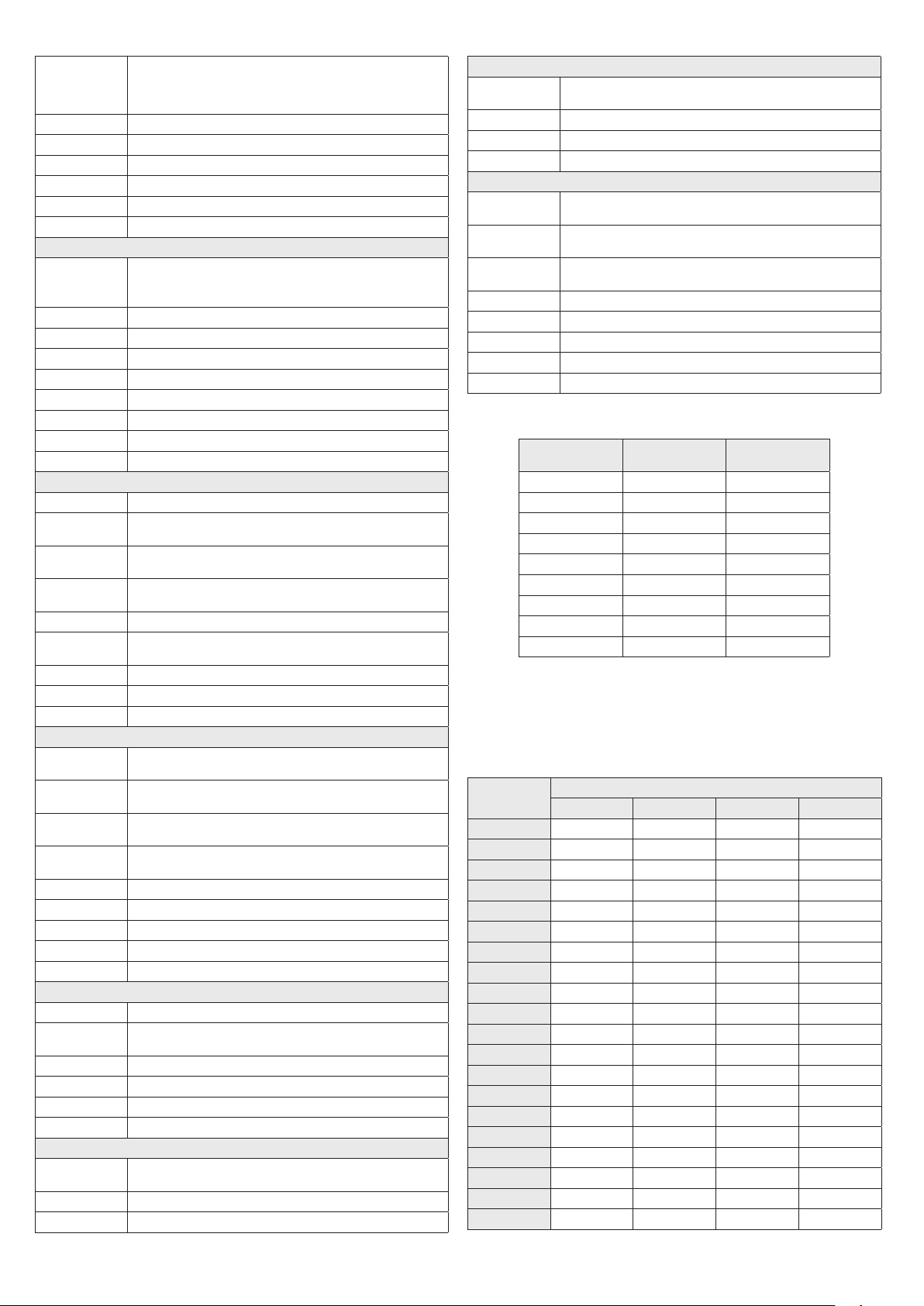
Wire gauge standards
Bare Wire Gauge(mm) American Wire Gauge
(AWG)
Cross-sectional Area of
Bare Wire (mm2)
0.750 21 0.4417
0.800 20 0.5027
0.900 19 0.6362
1.000 18 0.7854
1.250 16 1.2266
1.500 15 1.7663
2.000 12 3.1420
2.500 4.9080
3.000 7.06 83
12 Vdc Wire Gauge and Transmission Distance
The following table shows the recommended maximum distance adopted for the dierent wire sizes
when the 12 Vdc voltage loss is less than 15%. For example, for a device with the rating power of
20 VA which is installed 77 feet (22 m) from the transformer, the minimum wire gauge required is
1.0000 mm (18 gauge).
Power (VA) Wire size mm (gauge)
0.800 (20) 1.000 (18) 1.250 (16) 2.000 (12)
10 97 (28) 153 (44) 234 (67) 617 (176)
20 49 (14) 77 (22) 117 (33) 308 (88)
24 41 (12) 64 (18) 98 (28) 257 (73)
30 32 (9) 51 (15) 78 (22) 206 (59)
40 24 (7) 38 (11) 59 (17) 154 (44)
48 20 (6) 32 (9) 49 (14) 128 (37)
50 19 (6) 31 (9) 47 (13) 123 (35)
60 16 (5) 26 (7) 39 (11) 103 (29)
70 14 (4) 22 (6) 33 (10) 88 (25)
80 12 (3) 19 (5) 29 (8) 77 (22)
90 10.8 (3.1) 17 (5) 26 (7) 69 (20)
100 9.7 (2.8) 15 (4) 23 (7) 62 (18)
110 8.9 (2.5) 14 (4) 21 (6) 56 (16)
120 8.1 (2.3) 13 (4) 20 (6) 51 (15)
130 7.5 (2.1) 11.8 (3.4) 18 (5) 47 (14)
140 7 (2) 11 (3.1) 17 (5) 44 (13)
150 6.5 (1.9) 10.2 (2.9) 16 (4) 41 (12)
160 6.1 (1.7) 9.6 (2.7) 15 (4) 39 (11)
170 5.7 (1.6) 9 (2.6) 14 (4) 36 (10)
180 5.4 (1.5) 8.5 (2.4) 13 (4) 34 (10)
Table of contents
Other ALIBI Security Camera manuals

ALIBI
ALIBI ALI-NS4112R User manual

ALIBI
ALIBI ALI-TS2118VR User manual

ALIBI
ALIBI ALI-NS1025VR User manual

ALIBI
ALIBI ALI-PTZ23X User manual

ALIBI
ALIBI ALI-TS3025R User manual

ALIBI
ALIBI ALI-TS3015R User manual

ALIBI
ALIBI ALI-BC1720EC User manual

ALIBI
ALIBI ALI-TP3005L User manual

ALIBI
ALIBI ALI-NS4002R User manual

ALIBI
ALIBI ALI-TS4115R User manual

ALIBI
ALIBI ALI-TS3012R User manual

ALIBI
ALIBI ALI-BC700G User manual

ALIBI
ALIBI ALI-NS2012R User manual

ALIBI
ALIBI ALI-CD700 User manual

ALIBI
ALIBI ali-bc1080e User manual

ALIBI
ALIBI ALI-NS4036RE User manual

ALIBI
ALIBI ALI-NS3012R User manual

ALIBI
ALIBI ALI-NS1012VRP User manual

ALIBI
ALIBI ALI-NS1012VR 2.1 User manual

ALIBI
ALIBI ALI-TP7012RH User manual