ALIBI ALI-NS1102VR User manual

1www.observint.com ALI-NS1102VR_CQ
190604
12 Vdc Power
connector
Ethernet connector -
PoE capable
Camera drop cable connectors
Camera
ground
terminal
Mounting
screw holes (3)
Drop cable
Camera base (mounting surface side)
What’s in the box
Box contains:
• This document
• Drill template
• Weatherproof Ethernet
tting
• Security L-wrench
• Mounting screws and
wall inserts
Weatherproof tting
for Ethernet cable
L-wrench
Mounting
screws and
wall inserts
Step 1. Route interface cables to the camera
Ethernet and power interface cables connect directly to the camera drop cable (see photo above). A ground
terminal is provided on the mounting surface side of the camera base (see photo above).
The ALI-AF4 junction box is compatible with the camera. If using this junction box, all connecting cables
should be routed into this junction box and attached to the camera within it.
NOTE
When selecting a mounting location for the camera
• Make sure that there are no reective surfaces near to the camera lens. IR light from the camera may
bounce back onto the lens causing reections.
• Determine how wiring is routed into the camera. The cable can be routed through conduit (a
threaded conduit adapter is provided), through the mounting surface and access hole in the
mounting plate, or through the side inlet.
The camera includes connectors for the following:
• Ethernet (required): The Ethernet drop cable can connect to a LAN extension cable from a switch
or Network Video Recorder. The camera can be powered across the LAN using power over Ethernet
(PoE) injection. See the Specications section at the end of this document for power requirements.
• 12 Vdc power input (optional if PoE powered, required if not): 12 Vdc drop cable includes
screw-down connectors, with the polarity embossed on the cable. ALWAYS COMPLY WITH THE
POLARITY INDICATED. Voltage input at the camera must be within the range 12 Vdc ± 25%.
ALI-NS1102VR 2.0 Megapixel
IP Dome Camera
Quick Installation Guide
This document guides you through the basic steps to install and congure the ALI-NS1102VR camera. This
camera features:
• 2 Megapixel 1/2.8"CMOS progressive scan sensor, 1920 × 1080 pixels @ 30 fps
• Dual-stream video support
• Video stream compression: H.265+, H.265, H.264+, H.264 standard and MJPEG
• Color: 0.01 Lux @ (F1.2, AGC ON), 0.028 Lux @ (F2.0, AGC ON) minimum illumination
3D-DNR noise reduction and Digital Wide Dynamic Range (WDR) and BLC
• 100 ft Smart IR range
• Dual power capable - Power over Ethernet (PoE) or 12 Vdc
• IP67 weatherproof rated, IK10 impact resistance rated, TVS 2000V lightning protection
• Compatible with ALI-AF4 junction box.
For more information about the features of these cameras, please refer to the ALIBI IP Camera
Software V2 User Manual. This document and other supporting publications can be downloaded from
AlibiSecurity.com/resources.
Mounting
base
Dome
Assembly
IR array
Lens
Gimbal
assembly
Tilt lock
screw
Dome
cable
Drop
cable
Black plastic
liner
Mounting
screw hole (3)
Reset button*
ALI-NS1102VR camera without the dome cover
* To RESET the camera to its default settings, press and hold the RESET button for 10 seconds while powering on the camera.
This resets the user name, password, IP address, port No., etc. to the factory settings.

2www.observint.com
• Ground: A ground terminal is provided for attaching an earth ground cable to the camera. Follow
local electrical codes for grounding procedures.
NOTE This camera includes the TVS 2000V lightning protection feature. To use this feature, refer to the
TVS 2000V section at the end of this document for implementation guidelines.
1. Route a LAN extension cable from a network switch or Network Video Recorder to where the
camera will be installed.
2. If the camera is not powered using PoE, route 12 Vdc power extension cables from an adequate
power source to the location where the camera will be installed. Voltage input at the camera can be
within the range 12 Vdc ± 25%.
CAUTION
Do not apply power to the camera at this time. Before applying power to the camera, ensure
that the polarity is correct. An incorrect connection may cause a malfunction and can damage
the camera.
3. Route an earth ground cable to the camera in compliance with local electrical codes.
Step 2. Install the camera
The camera can be mounted on a wall or ceiling, or installed onto an ALI-AF4 junction box.
Installing the camera onto a wall or ceiling
Screws and wall inserts included with the camera are adequate for most surfaces, but more appropriate
fasteners may be needed. The mounting surface should support at least three (3) times the weight of the
camera and mounting bracket assembly.
1. Determine the best fasteners for securing the camera to mounting surface. The mounting hardware
provided is suitable for most surfaces. NOTE: A mounting plate adapter is provided for attaching the
camera to a junction box.
2. Using the Drill Template
provided, mark the location of
the mounting screw holes. If
the drop cable will be routed
through the mounting surface,
mark the location of the hole
for the cable. NOTE: The drop
cable can be routed through
the cable channel on the side
of the base.
3. Drill holes for the mounting
fasteners, and for the drop
cable if needed.
4. Remove the three lower
dome screws, then separate
the lower dome from the
mounting base. A security
wrench is provided.
5. Route the drop cable as
planned, then secure the
mounting base to the surface
with the fasteners.
Mounting
screw holes
Wall inserts
Mounting
base
Mounting
screws
Drop
cable
6. DO NOT reattach the dome assembly to the mounting base at this time.
Installing the camera with a junction box
1. Install the junction box at the installation location.
2. Route the interface cables into the junction box.
Step 3. Connect the camera to the LAN, ground and power
1. Attach a ground cable to the camera in accordance with local electrical codes.
2. Connect the
LAN extension cable to the camera network drop cable. If the camera is in an
environment where dust, moisture or other contaminants are present, use the Waterproof Ethernet
Fitting provided to seal this connection. Instructions for using the Waterproof Ethernet Fitting are
provided at the end of this guide.
Camera Ethernet switch
Network drop cable
from camera Network cable from
router or switch
Waterproof Ethernet Fitting installed
WARNING
!
Failure of the power or Ethernet connector due to moisture or an other
contaminant is considered an installation error, which voids the warranty. If
installing this camera in a location such as an overhang, shop, garage, kitchen,
etc. where high humidity or dust is present, seal these connections adequately.
3. If the camera is not powered using PoE, connect the 12 Vdc power cable to the 12 Vdc connector on
the camera drop cable. The polarity of the drop cable connector is shown below.
CAUTION
Before applying power to the camera, ensure that the polarity is correct. An incorrect connection
may cause a malfunction and can damage the camera.
4. Seal the power cable connectors as needed from moisture and other contamination.
5. If installing the camera with a junction box:
a. Detach the dome assembly from the camera base.
b. Attach the camera base to the junction box. Ensure the seal is properly positioned.
6. Power on the camera.
Step 4. Install the Alibi Config Tool software
NOTE: If the camera LAN extension cable is attached to a Network Video Recorder (NVR), skip this step.
The Alibi Cong Tool is a PC-based network utility for discovery of Alibi compatible devices. It provides
an easy way to activate devices, congure camera and recorder network conguration settings, and set
device passwords. It can be installed on a Microsoft® Windows® operating system that has direct access
to the network where your Alibi devices are installed. You can download the Alibi Conguration Tool from
AlibiSecurity.com/Resources.
1. Download the Alibi Cong Tool from the AlibiSecurity.com/Resources website. At the time when
this document was published, the le is named: alibi-cong-tool.zip and is about 80MB.
2. Un-zip the le on a computer with Microsoft Windows (Windows 7 or newer) that is connected to
the LAN where your Alibi camera is connected.
3. Run the le contained in the zip le: Alibi Cong Tool.exe. Follow the on-screen instructions to
install the le.
4. Open the Alibi Cong Tool application. When the application opens, it automatically “discovers” and
lists all Alibi compatible devices on the LAN. See below.
NOTE In the screen above, the tool can discover devices on other sub-nets. It will also list other Alibi compatible
devices on the LAN, and devices with the address 192.168.1.64 (an inactive Alibi device).
© 2019 Observint Technologies. All rights reserved.

3www.observint.com © 2019 Observint Technologies. All rights reserved.
Step 5. Activate Inactive Alibi device
NOTE: If the camera LAN extension cable is attached to a Network Video Recorder (NVR), skip this step.
Refer to the documentation available for your NVR rmware for the procedure to activate the camera, if
necessary.
When an Alibi device is rst installed, or reset to its factory conguration, it must be “Activated” before it
can be used. In the Alibi Conguration Tool, “Inactive” devices have a Security status of Inactive, and
an IPv4 address of 192.168.1.64. A device is “Activated” when a password is assigned to the admin
username of the device.
In the example below, an ALI-NS1102VR camera is activated and congured for its network. The procedure
is similar for all other Alibi network cameras currently available.
1. Scan through the list of devices the Alibi Cong Tool discovered for the Inactive device you want to
activate (see below). Click on the device in the list to highlight it, and then click the select box to
check it. See below.
ActivateSelected
2. Click the Activate button. In the Activate window, you will create a password for the admin
(administrator) username.
a. In the Activate window, enter an a password for admin in the New Password eld. Include a
combination of uppercase, lowercase alphabetic characters and numbers to create a “Strong”
password. The rating is shown beneath the Password eld. See above.
b. Enter the admin password again in the Conrm eld, and then click Activate. In the screen
below, notice that the device Security status shows “Active”. Record your admin password for
reference later.
CAUTION
If you lose your admin (administrator) password, you cannot congure the device or restore
it to its factory settings. To reset your password, call your support organization for specic
instructions.
Notice that although the device is now activated, it retained the default IP address.
Step 6. Edit Network Parameters
NOTE: If the camera LAN extension cable is attached to a Network Video Recorder (NVR), skip this step.
The camera will receive network conguration settings from the NVR. Refer to the documentation available
for your NVR rmware for more information.
You can change the network parameters of devices that are active.
1. In the list of devices discovered, click on the device you want to change the network settings for, and
then click the select box to check it. See below.
Edit Network Parameters
2. In the popup window, edit the current network parameters, and then enter the Administrator
(admin) user password in the eld at the bottom.
a. Enable DHCP: You can select Enable DHCP to acquire compatible network settings from
a DHCP server installed on the LAN. However, these settings might be changed later by the
DHCP server. Since it is recommended to use an unchanging IP address, you can use DHCP
to acquire compatible network settings, and then uncheck Enable DHCP and save that
conguration to retain the new network parameters.
b. In the example below, Enable DHCP was checked to acquire compatible network settings
from the DHCP server.
3. Click OK to save your settings. The parameter change(s) will be shown device’s network parameters
(see below).
Step 7. Login to the camera
NOTE: If the camera LAN extension cable is attached to a Network Video Recorder (NVR), skip this step.
Microsoft® IE is used to access your camera remotely. IE must run as an Administrator to use all features
available through a remote login to the camera.
Setting MS Internet Explorer to run as an Administrator
Window 7: To run IE as an Administrator:
1. Find or create an IE icon on your computer desktop.
2. Hold down the shift key, and then right-click on the IE icon.
MS Internet
Explorer icon
Run as administrator
3. Click Run as administrator in the pop-up menu.
Window 10:
To run IE as an Administrator:

4www.observint.com © 2019 Observint Technologies. All rights reserved.
1. Find MS IE in the start menu. Usually this is found in the Windows Accessories group.
2. Pin the entry to Start.
3. Right click on the Internet Explorer tile, and then select More | Run as administrator.
Run as
administrator
To login to the camera from a computer on the same LAN:
1. Open your Microsoft Internet Explorer (IE) browser on your computer and enter the IP address of the
camera in the URL eld. In the example below, the IP address of the camera is 192.168.0.7.
2. In the login window, enter admin for the User Name and the password you created in the
Password eld, the click Login.
3. If this is the rst time you are logging into a camera, you may see the message in the following
screen. If this appears, follow the sub-steps below.
a. Click on the message to install the plugin.
b. In the message bar at the bottom of the screen, click Run. Follow the on-screen instructions
to install WebComponents. When the following screen opens, click Finish.
The Live View screen with the camera video image should appear.
Capture, Record, Zoom icons
Screen select tabs Logout buttonLive View image
Step 8. Adjust camera pan and tilt
Adjust the camera pan and tilt to point the camera at your surveillance target. When pointing the camera,
use the Live View display on a recorder or remote login.
1. Detach the camera dome assembly from the camera base, if necessary.
2. While observing live video from the camera, grasp the camera gimbal at the pivot points on both
sides, and then rotate it to point in the direction of your surveillance target.
Pan range:
0˚ ~ 355˚
Grasp on
sides to
turn
Grasp on
sides to
turn

5www.observint.com © 2019 Observint Technologies. All rights reserved.
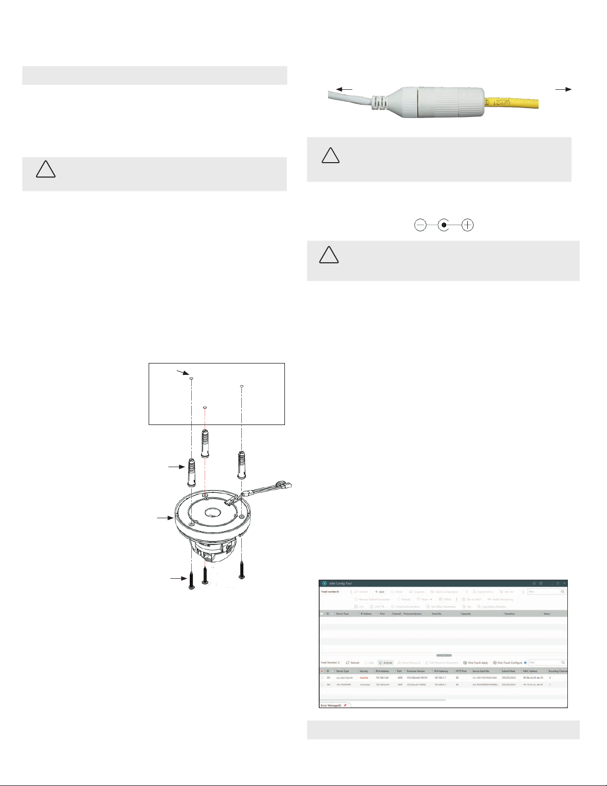
To adjust the tilt, slightly loosen the tilt lock screws on both sides of the gimbal, grasp the camera
head and tilt as needed for the image height in the Live View display. Retighten the screws.
Tilt range:
0˚ ~ 75˚
Tilt lock screw (on each side)
3. Ensure the dome assembly is clean and dust free, and then reinstall it.
4. Refer to the recorder or camera rmware user manual for conguration adjustments to the camera.
Specications
Camera
Image Sensor 1/2.8” progressive scan CMOS
Min. Illumination Color: 0.01 Lux @ (F1.2, AGC ON), 0.028 Lux @ (F2.0, AGC ON);
Shutter Speed 1/3 s ~ 1/100, 000 s
Slow Shutter Yes
Auto-Iris No
Day & Night IR cut lter
Digital Noise Reduction 3D DNR
WDR Digital WDR
Angle Adjustment Pan: 0° to 355°, tilt: 0° to 70°
Lens
Focal Length, FOV 2.8 mm, horizontal FOV 114°, vertical FOV 62°, diagonal FOV: 135°
Aperture F2.0
Focus No
Lens Mount M12
IR
IR Range up to 100 ft Smart IR
Wavelength 850 nm
Compression Standard
Video Compression Main stream: H.265 / H.264
Sub-stream: H.265 / H.264 / MJPEG
H.264 Type Baseline Prole / Main Prole / High Prole
H.264+ Main stream supports
H.265 Type Main Prole
H.265+ Main stream supports
Video Bit Rate 32 Kbps ~ 8 Mbps
Smart Feature set
Region of Interest (ROI) 1 xed region for main stream and sub-stream
Image
Max. Resolution 1920 × 1080
Main Stream Max. Frame Rate 50 Hz: 25 fps (1920 × 1080, 1280 × 960, 1280 × 720)
60 Hz: 30 fps (1920 × 1080, 1280 × 960, 1280 × 720)
Sub-stream Max. Frame Rate 50 Hz: 25 fps (640 × 480, 640 × 360, 320 × 240)
60 Hz: 30 fps (640 × 480, 640 × 360, 320 × 240)
Image Enhancement BLC, 3D DNR
Image Settings Saturation, brightness, contrast, sharpness, AGC, white balance adjustable by client software
or web browser
Day/Night Switch Auto, Scheduled
Network
Alarm Trigger Motion detection, video tampering alarm, illegal login
Protocols TCP/IP, ICMP, HTTP, HTTPS, FTP, DHCP, DNS, DDNS, RTP, RTSP, RTCP, NTP, UPnP™, SMTP, IGMP,
802.1X, QoS, IPv6, UDP, Bonjour
General Function Anti-icker, heartbeat, mirror, password protection, privacy mask, watermark
API ONVIF (PROFILE S, PROFILE G), ISAPI
Simultaneous Live View Up to 6 channels
User/Host Up to 32 users 3 levels: Administrator, Operator and User
Client Alibi Central Management Software (ACMS) v3.1 or later, ACMS-XP
Web Browser Microsoft©Internet Explorer©7 and later
Interface
Communication Interface 1 RJ45 10M/100M self-adaptive Ethernet port
General
Operating Conditions -22 °F to 122 °F (-30 °C to 50 °C), humidity: 95% or less (non-condensing)
Power Supply 12 Vdc ± 25%, 5.5 mm coaxial power plug
PoE (802.3af, class 3)
Power Consumption and
Current
12 Vdc: 0.4 A, max. 5 W;
PoE: (802.3af, 37 V ~ 57 V), 0.2 A ~ 0.13 A, max. 6.5 W
Protection Level IP67 weatherproof, IK10 impact resistance
TVS 2000V lightning protection, surge protection and voltage transient protection
Material Plastic and metal
Dimensions Φ 4.4” × 3.2” (Φ 111 mm × Φ 82.4 mm)
Weight Camera: approx. 0.9 lb. (410 g)
With package: Approx. 1.3 lb. (610 g)
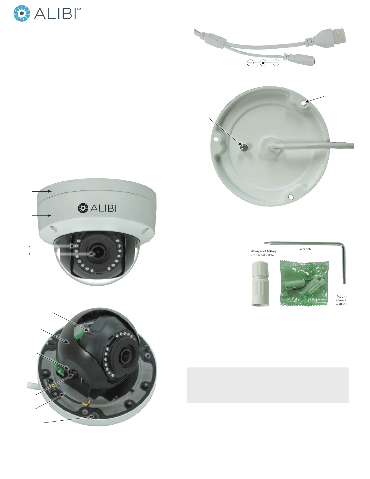
Using the Waterproof Ethernet Fitting
Install the Waterproof Ethernet Fitting on the Ethernet cable end at the camera when moisture or
contamination exists in the area near the camera. The tting includes several parts that must be installed in
a specic order. To install the tting:
1. Place the rubber O-ring over the camera drop cable end cap.
Push the O-ring up to the connector cap.
2. If an RJ-45 connector is installed on the network cable, from
the router or switch, remove it.
3. Place the Lock Nut onto the network cable from the router
or switch as shown in the drawing to the right. The inside
threads must be toward the camera end.
4. Place the rubber basket onto the network cable above the lock
nut as shown.
5. Place the end cap onto the network cable above the rubber
gasket as shown. The ngered end must be toward the router
or switch.
6. Install an RJ-45 connector onto the network cable.
7. Plug the RJ-45 connector with the network cable into the
camera network drop cable.
8. Fit the end cap on the network cable onto the camera drop
cable end cap. Rotate the network cable end cap to lock it in
place.
9. Push the rubber gasket fully into the end of the network cable
end cap.
10. Screw the lock nut onto the network cable end cap until it is
fully seated.
Network drop
cable from
camera
Network cable from
router or switch
Fitting assembled
Waterproof Ethernet Fitting assembled and connected
Drop cable
end cap
Network drop
cable from
camera
Rubber
O-ring
seal
RJ-45
connector
End cap
Rubber
gasket
Network
cable
from
router or
switch
Lock nut

6www.observint.com © 2019 Observint Technologies. All rights reserved.
TVS 2000V Lightning and Surge Protection Feature Guidelines
This product includes TVS plate lightning protection technology to prevent damage caused by a pulse
signal that is below 3000 watts from sources such as lighting, surging, etc. Protection measures must be
taken to ensure electrical safety.
• The distance between signal transmission line and high-voltage equipment or high-voltage cable
is at least 50 m.
• Outdoor wiring should better be along the eaves as much as possible.
• In the open eld, wiring should be buried underground in sealed steel pipe with one-point
grounding. Overhead routing method is not acceptable.
• In regions with thunderstorms or where high induction voltage are present (such as high-voltage
transformer substation), high power lightning protection apparatus and lightning conductor are
necessary.
• The design for installation and wiring with lightning protection and grounding should be combined
with the lightning protection consideration of the building, and conform to the relevant national
and industry standards.
• The system should ensure equipotential grounding. Grounding equipment must satisfy both system
anti-jamming and electric safety. It must not allow short circuit and open circuit with the zero
conductor of strong grid. When the system is singularly ground, the resistance must less than 4 Ω
and the cross-sectional area of the grounding cable must be no less than 25 mm2. For grounding
instructions, refer to local electrical codes and this manual.
Lightening rod
Communicate
arrester
Video arrester
Power arrester 45°conical
envelope
The resistance of
earthing conductor
must be less than 4 Ω.
The camera should be
within a 45°envelope
under the lightening rod.
Steel jacket
Lightning & Surge Protection
Wire gauge standards
Bare Wire Gauge(mm) American Wire Gauge
(AWG)
Cross-sectional Area of
Bare Wire (mm2)
0.750 21 0.4417
0.800 20 0.5027
0.900 19 0.6362
1.000 18 0.7854
1.250 16 1.2266
1.500 15 1.7663
2.000 12 3.1420
2.500 4.9080
3.000 7.0683
12 Vdc Wire Gauge and Transmission Distance
The following table shows the recommended maximum distance adopted for the dierent wire sizes when
the 12 Vdc voltage loss is less than 15%. For example, for a device with the rating power of
20 VA which is installed 77 feet (22 m) from the transformer, the minimum wire gauge required is 1.0000
mm (18 gauge).
Power (VA) Wire size mm (gauge)
0.800 (20) 1.000 (18) 1.250 (16) 2.000 (12)
10 97 (28) 153 (44) 234 (67) 617 (176)
20 49 (14) 77 (22) 117 (33) 308 (88)
24 41 (12) 64 (18) 98 (28) 257 (73)
30 32 (9) 51 (15) 78 (22) 206 (59)
40 24 (7) 38 (11) 59 (17) 154 (44)
48 20 (6) 32 (9) 49 (14) 128 (37)
50 19 (6) 31 (9) 47 (13) 123 (35)
60 16 (5) 26 (7) 39 (11) 103 (29)
70 14 (4) 22 (6) 33 (10) 88 (25)
80 12 (3) 19 (5) 29 (8) 77 (22)
90 10.8 (3.1) 17 (5) 26 (7) 69 (20)
100 9.7 (2.8) 15 (4) 23 (7) 62 (18)
110 8.9 (2.5) 14 (4) 21 (6) 56 (16)
120 8.1 (2.3) 13 (4) 20 (6) 51 (15)
130 7.5 (2.1) 11.8 (3.4) 18 (5) 47 (14)
140 7 (2) 11 (3.1) 17 (5) 44 (13)
150 6.5 (1.9) 10.2 (2.9) 16 (4) 41 (12)
160 6.1 (1.7) 9.6 (2.7) 15 (4) 39 (11)
170 5.7 (1.6) 9 (2.6) 14 (4) 36 (10)
180 5.4 (1.5) 8.5 (2.4) 13 (4) 34 (10)
Table of contents
Other ALIBI Security Camera manuals

ALIBI
ALIBI ALI-NS1004VR User manual

ALIBI
ALIBI ALI-NS1044VR User manual

ALIBI
ALIBI ALI-CD1080PVF User manual

ALIBI
ALIBI ALI-BC1720P User manual

ALIBI
ALIBI ALI-TP7012RH User manual

ALIBI
ALIBI ALI-NS3034R User manual

ALIBI
ALIBI ALI-IPU3130R User manual

ALIBI
ALIBI ALI-TP2118VR User manual

ALIBI
ALIBI ALI-NP1013VRH User manual

ALIBI
ALIBI ALI-TS1025R User manual

ALIBI
ALIBI ALI-NS1034R User manual

ALIBI
ALIBI ALI-TS1112R User manual

ALIBI
ALIBI ALI-CD1720EC User manual

ALIBI
ALIBI ALI-TS4012R User manual

ALIBI
ALIBI ALI-NS2012VR User manual

ALIBI
ALIBI ALI-NS4116R User manual

ALIBI
ALIBI ALI-TS3012R User manual

ALIBI
ALIBI ALI-NS1025VR User manual

ALIBI
ALIBI ALI-TS2025R User manual

ALIBI
ALIBI ALI-NS4114R User manual